8. Computer controlled machining
This week we met in our lab and did the group part of the project. But Spring Break is this week at Wheaton, so what follows is our group explorations and my design. I will get into the lab when everyone is back next week.
Additional work this week for me was to hold the panel for the grant program I direct through the Mathematical Association of America (MAA). The Tensor Grants for women and girls in mathematics support activities for these populations in middle school through professionals. It’s a great initiative and I feel very fortunate to be able to contribute to the math community in this way.
Some useful links
- CNCSourced Basic Furniture Ideas: 21 Furniture Ideas you can Make at Home
- A cool chair that incorporates a “living hinge” design
- Info about downcuts vs upcuts
Group Work
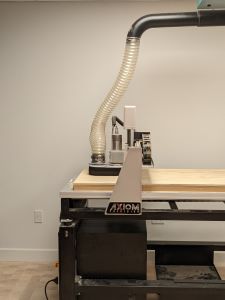
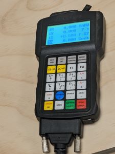
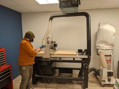
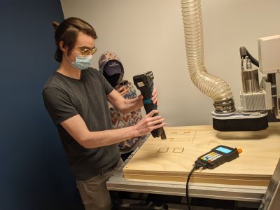
None of us in the group have ever used the CNC router so I feel like this was the first week we were all on the same level in terms of learning machinery. The CNC (Computer numerical control) machine that we have, an Apex, is like a larger, more powerful laser cutter. Images below with Apex, Spencer our teacher with the Apex running and the controller.
There were 3 functions we learned about: cutting, pockets, engraving. We used Vcarve as the software to take in a design and then create gcode to send to the machine (through a thumbdrive and Apex was picky about when it would decide to read the thumbdrives).
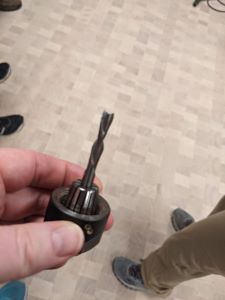
Some things to make sure of before you start: make sure you have the right kind of bit. Is it up or down cut - you can twist the bit clockwise in your hand to see which one you have. But what do they do? A downcut bit cuts from the surface down and makes for a clean top surface, according to the website linked above. The bottom is not clean though bc as it cuts, the bits force the wood chips down. Upcut bits are useful when you want a clean bottom surface because it pulls out the cut chips.
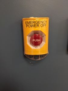
Some images before you start: one of the endmills (a 1/4 in downcut is what we used, but this is just a random endmill) we used; making sure we are being safe (safety glasses and ear coverings are necessary); and knowing where the kill switch is on the wall - if something goes wrong, we need to hit this (there is a kill on the Apex controller, but there is an overall kill for the room in case of an emergency)

We used 1/2 inch plywood that was 2 feet by 4 feet. Before we could cut we needed to screw the wood to the base, set the correct z-height, as in when we used the mills. We used the z-probe for that. This is done after we put the correct endmill in the machine. Here are images of the screwed wood (on each corner) z-probe and an example of Vcarve:
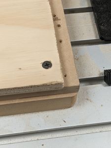
One of the things to make sure of with the z-probe is to make sure that you put the z-probe in far enough that it’s not near the edge, as the height there will likely be less bc it’s screwed down in the corners.
As I said, we engraved, cut and created pockets. One thing to make sure of when you are cutting out pieces is to add tabs so wood does not go flying across the room! This can be done in Vcarve after you bring in a design (for us from Fusion360). Pockets are cuts that do not go all the way through the material, but clear out the material in a space. It seems like engraving, except that you are going deeper and you are clearing out more space, FOR something. Like you want an indentation for a specific reason. Below are images of engraved, the cut with tabs and then pockets with the cut pieces.

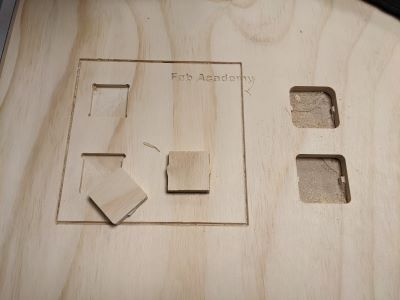
When you have tabs, then you have to use a small hand saw to get the pieces out after cutting. Brandon showed us how to do that and we all had a chance to try it.
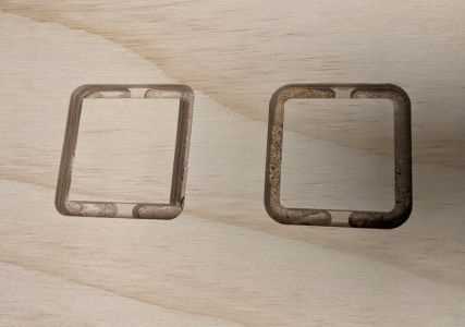
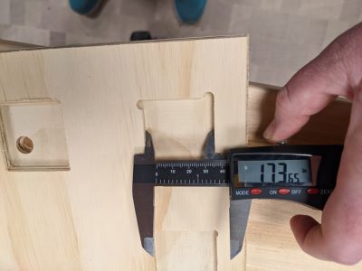
We were able to measure the difference between the pockets and the cut pieces that were supposed to fit in them. Not surprisingly, the pockets were SMALLER than the pieces we cut. When the APEX cuts pockets, there should be a margin of error so that the pieces we cut (of the same dimension) actually fit. You can see below that we measured the pockets to be 1.73 inches when the squares were 1.75 inches. We also put dogbones and tbones in the pockets to see if we could tell a difference and determine what was best (neither was big enough in the end still). While things were not far off, they were different enough so that things didn’t fit.
Individual work
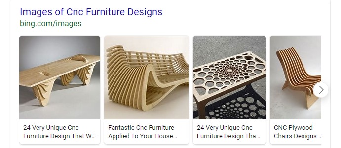
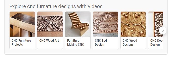
I was inspired by some cool CNC cut furniture. Some of the cool things I found are below:
At some point I would love to make some wood cut something that curved. I didn’t do that this week, but it’s a goal (unfortunately doesn’t fit into my final project though, so it might happen post Fab Academy).
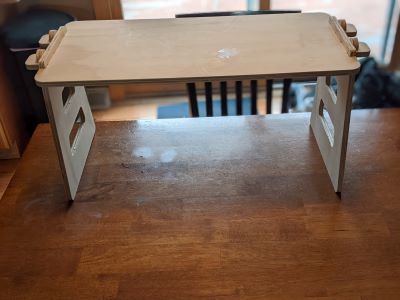
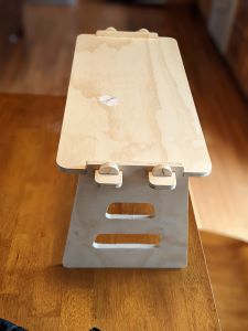
I decided to make a lap desk that could be used for work or meals on the couch, in bed, etc. I should reserve these spaces for no work and no food, but such is life!!
Fusion 360 Design
I made an early version of the desk and then Spencer suggested that I make the sides inset and I added more connection pieces for stability. Here’s my first version that I didn’t cut:
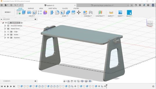
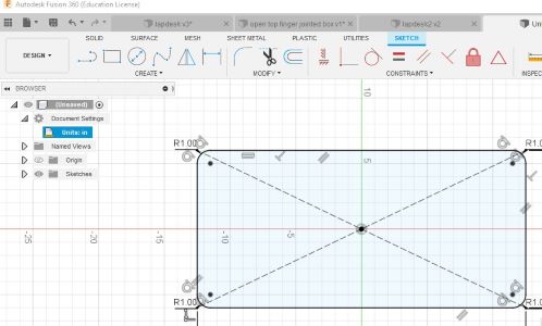
I designed a rectangular top with curved corners (thanks to the fillet command) and then added the connectors for the sides. Finally I extruded that shape to be the height of the plywood (1/2 in). The images of the steps are below:
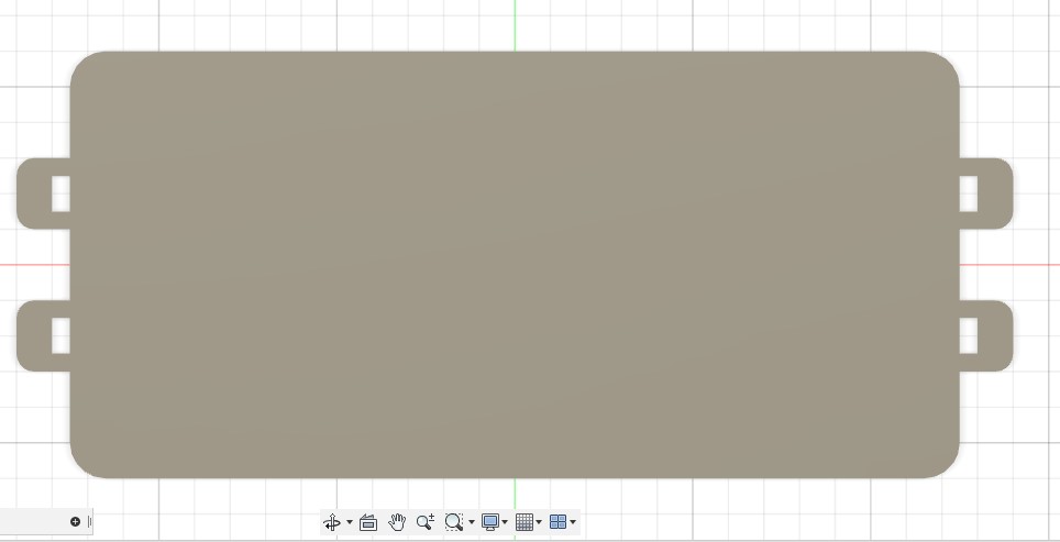
I had to add sides that were both inset and matched the tabs from the top. These were created using the combine feature and making sure I was using the right tool vs
CNC and Vcarve
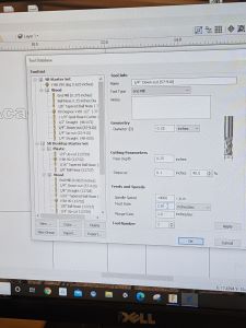
I used VCarve to prep the file for the CNC machine. There are several steps that you have to go through when you use this software to end up with the paths that the CNC machine will understand to cut. In this project I was only cutting - not using pockets or engraving, so only cut was necessary for the entire thing, though we did each part separately, so I set up 3 different files: side, top and pins. I needed only one file - the cut file - from VCarve for each and could use the same parameters. The plywood was 1/2 inch plywood, so the cut depth was 1/2 inch. I used 2 passes, so the pass cut was 1/4 inch. The feed was 2 in/sec at a speed of (no idea!!).
This week was not my best documentation. I could just make up info, but I will admit I just didn’t write it down. So I can’t tell you all the info about what I asked VCarve to do. I also don’t have screenshots from steps in VCarve (just the one below). I did document this better in the molding and casting week. So you can go there to find more info on VCarve.
Here is a video that provides a basic intro to VCarve since you’re not getting this info from my documentation.
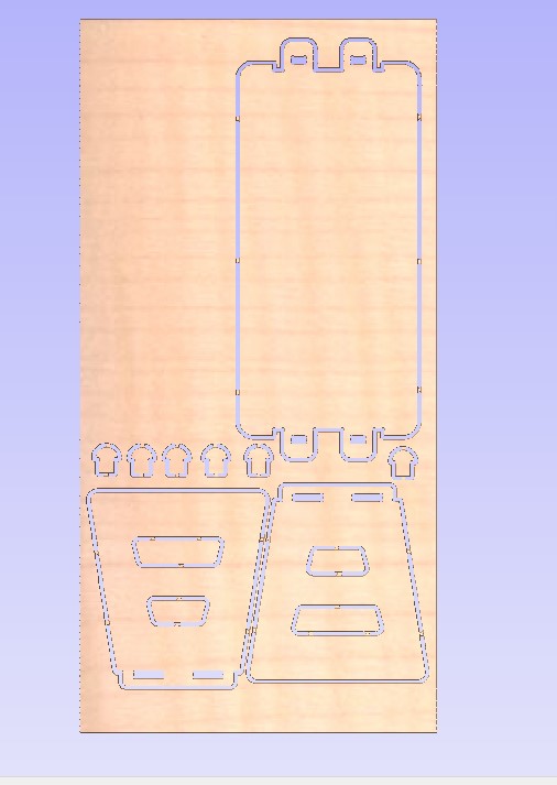
The highlights: one file for the whole desk. I could fit it all on one pieces of plywood that was 2 feet by 4 feet. I added tabs to all my pieces so they wouldn’t go flying off the machine when they were cut. I wasn’t smart about this because the little connector pieces should have had tabs on the flat side only. I don’t know why I thought I needed 2 when the pieces were so small. In the end the tab on the rounded top made the final product not smooth on top.
Here’s the expected output from VCarve:
TO use the CNC machine I followed the steps outlined above from our lab session. I attached the plywood by screwing down the corners. I set the origin for x and y at the bottom left corner. I used the z-probe and found a lowest point to set the z-origin so that the whole thing was cut all the way through. Then it was go time. The CNC control is very straightforward, select the file and set it to go. You have to make sure to turn on the filter before starting.
Images from a couple of different angles of the final lap table: