Final Project
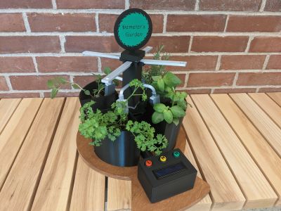
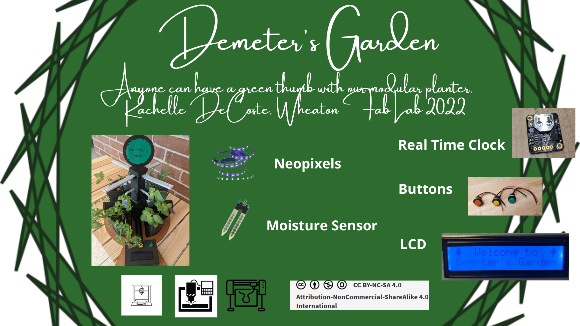
I designed a modular planter to grow herbs inside. The planter is designed so that the user could order as many pieces as they want and put them together with a base if this were to be further developed. Each planter will have its own LED light source to simulate sunlight. I added an additional device to indicate if the plant has enough water. We often over or underwater our plants, so this also seemed useful. The ideal user would be someone who doesn’t have a lot of natural sunlight available to them for indoor plants. I call the project “Demeter’s Garden.” The name is inspired by my daughter who is obsessed with Percy Jackson and I heard the name Demeter in a song from the Percy Jackson musical. Demeter is the goddess of harvest and agriculture, so it seemed fitting.
Moisture sensor
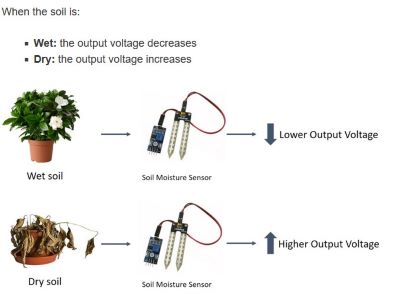
I am using Keeyees High Sensitivity Soil Moisture Sensors to measure the moisture levels in each of my plants. The sensor comes with a board that reads the moisture level and sends either analog (numbers between 0 and 1023) or digital (HIGH or LOW). Seems like I’ll have more control over analog. The sensor reads 1023 if there is no moisture when I try it out with an Arduino Uno. I found a nice sample of how to set up the sensor with some LEDs at the Random Nerd Tutorials Site.
How does the sensor work? When the soil is wet, the voltage decreases and so you see the output analog numbers go down. When it’s dry the voltage increases. This is a nice visual from that site:
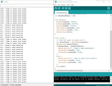
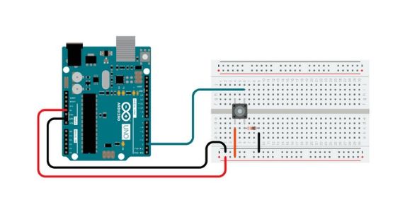
Also, here’s the Arduino, bread board set up that I followed.
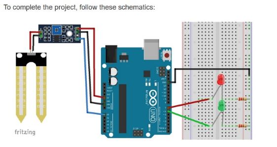
Below is an image for the output next to the Arduino ide program. NOTE: when I use my own board I should rerun this so I can find the threshold levels for my board. It may NOT be 800. I will have to estimate it…hmmmmm....something to think about.
“Packaging” for lack of a better word.
The moisure sensor has a weird shape that needs to be accommodated for a cover. It has a thickness at the top because of the wiring.
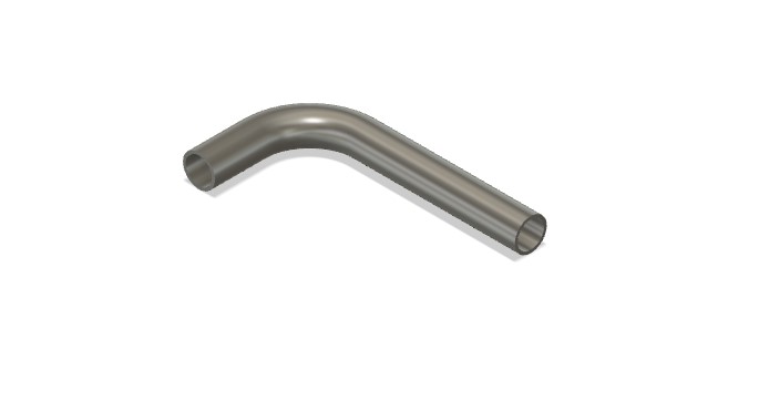
Also, the wires going from the casing for the moisture sensor are going to meet up wtih the wiring for the neopixels. Thus we need wire coverings. I was trying to figure out how to make an elbow joint. I found this video that helped. I basically created a path and then used the sweep command in Fusion360. I created the path by making a right angle with both sides the length I wanted and then curving the corner (is it called fillet in 2d?). You can find the final design below.
LCD
We used an LCD in the group project, but mostly my classmate Kobe worked on that. So I decided to incorporate one into my project. I’m using a SunFounder IIC 12C TWI 1602 Serial LCD Module Display. I decided I really need to start from scratch with my understanding. Again, using a bread board and Arduino uno I worked from this site from Einstronic. Here’s their image for the set up.
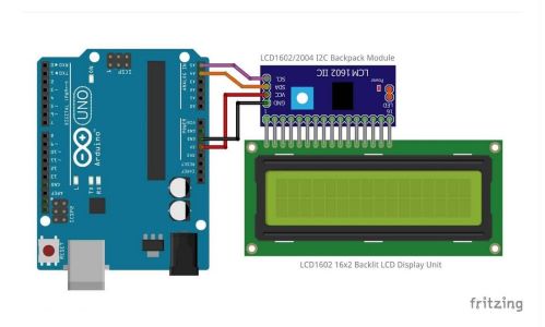
Note: we are using an I2C backpack here, which makes connecting to a board so much easier. This remains true when I switch to my own board. Here you only need 4 connecting pins - GND and VCC (of course), as well as SDA and SCL pins. Note that the Arduino UNO has 2 sets of these types of pins. This tutorial suggests using A4 for SDA and A5 for SCL. For the Attiny 1616 there is only one of each. Thus, since the clock requires these pins too, I thought I was going to need to set up 2 boards in serial. Turns out you can use the same SDA and SCL pins on the ATTiny since the different devices have different libraries. You can see that in my board design below.
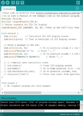
We needed to add the library for the LCD in our Arduino code. Here the page suggests that we need LiquidCrystal I2C by Frank de Brabander version 1.1.2. It reminds us to do this by going to Sketch>Include Library>Manage libraries… Then you search for the library indicated above. Well, I don’t see the one above, but have already installed the one from Marco Schwartz from the group project. Let’s see if we can make that work instead.
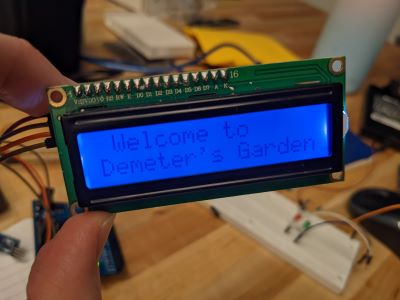
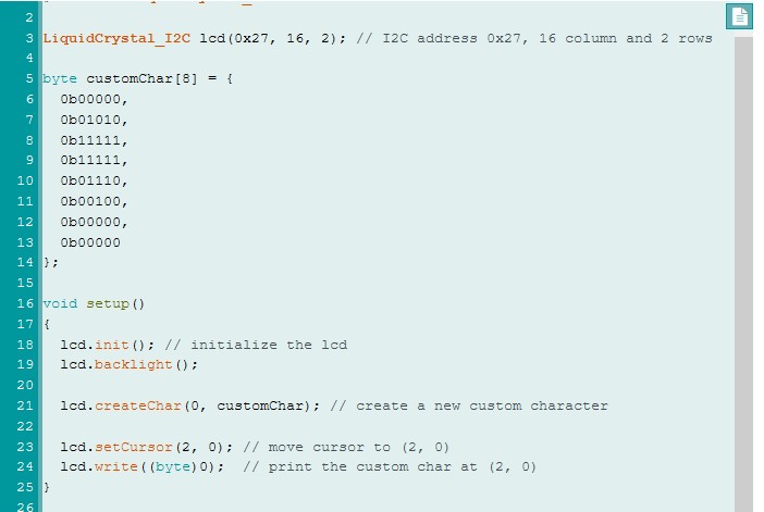
And it did. So here’s the code and an image of my ouput!!
Working with LCD screens day 2 (June 2 2022)…
It turns out that I had my orientation of the coordinates wrong. I was thinking mathematically, like I was looking at entries of a matrix where (a,b) means the ath row and the bth column. But here it’s backwards. I tried to put the 2nd line of code in (1,0) and that didn’t work bc that’s the 2nd column in the first row. So yes, the columns and rows are also numbered from zero. Nice image from Arduinogetstarted.com on the 16x2 LCD. Now that I know more I might have gotten the 20x4. Oh well.

NOTE: if you scroll down that page there is a “trouble shooting” section and there are 2 things here that are probably useful - adjust brightness by rotating the pentiometer (looked into this bc it’s really bright on day 2) AND how to find the address. This was default of 0x27 Again: https://arduinogetstarted.com/tutorials/arduino-lcd-i2c
The pentiometer bit was pretty easy. You just rotate the button and it changes the brightness.
Totally random and not necessary, but fun. You can create your own custom characters and the same page Arduino Get Started has an interactive section that allows you to choose the arrays that you want and it spits out the code. For instance, I’m going to try to make a leaf (ha, that would be cute!). To do so I need to define the following
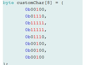
The sample that is on the webpage is a heart. You can see how that is defined and then used in the output on the LCD.
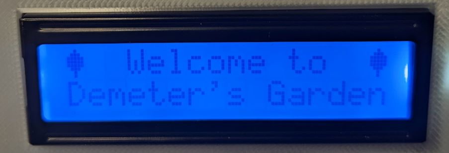
I made this work and created some plant leaves for Demeter’s Garden!! I can’t get a great photo, but here’s one.
Buttons
We have done several projects with buttons (well, one main one and then they were used in the group project), but I’m going to start from basics here. Going to work on making sure I can get one button to work. Going to plan to incorporate neopixels and then also to make sure the screen, button and neopixels can all interact. That’s the goal for today (Thursday June 2). After that I plan to go back to make the moisture sensor and neopixels interact - well, really have the moisture sensor turn on not just the LEDs, but the neopixels. That should be pretty straightforward from yesterday’s work, but also need to start working with the neopixels and the numbering, etc. That will be its own section below. First to buttons....
Ok, so we first just use the Button example code and turn on the builtin LED in the Arduino Uno using the following schematic from this site. Note: the resistor is a 10k ohm.
Next I set up the bread board with 2 buttons and 2 LEDs and had the buttons turn on/off one LED each. I found the setup and code here. I made this work (it took way longer than it should have - still having to make sure I have all the wiring right) but it worked. I then added a third button and a third LED because I’m going to have 3 buttons in my project. This was an easy add after making the 2 work.
Now I will use the buttons for the actual final project. The ones on the bread board aren’t the ones I want to use. I’m going to use these from Shin Chin. They should easily attach to the mounting that I plan to design and 3d print. Note: one important piece of info is that the diameter of the bottom shaft is 14.8mm.
Here’s what I’ve got for the buttons as a semi-final desgn. I actually changed to a black filament. I think it looks nice in the end with the black planters.
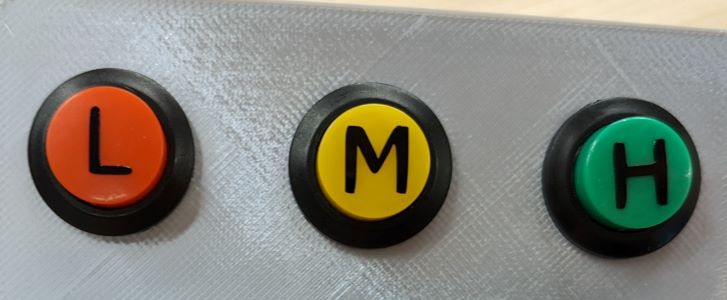
NOTE: L corresponds to low number of light hours (6 hours, 10am until 4pm), M corresponds to medium (9 hours, 10am until 7pm) and H corresponds to high (12 hours, 10am until 10pm). Now you see why the real time clock is necessary!
Real Time Clock
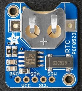
I learned about the clock through this Adafruit site that provides an overview of the piece. Here’s a screenshot of the version I am using from that site:
The page says that the device can share the I2C pins with other sensors as long as they don’t have an address collision. So the address of the real time clock is 0x68. Remember the screen was 0x27 (note I thought this was a zero but then I saw the letter “o” somewhere - the zero worked when I was using the LCD, so I’m going to assume that is correct for now.)
Note: there are 5 pins: VCC, Ground, SDA and SCL, and then SQW. The first four are the ones that are relevant. The last one is for “square wave output” which I will not be using (nor do I know what that really is, so that’s for another day). Note: the RTC has internal pull-ups on both the SCL and SDA so I don’t have to worry about adding resistors.
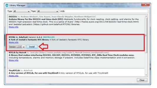
To use the RTC (real time clock) with my board later I will solder the pins into place and insert a CR1220 3v Lithium battery. To use the Arduino IDE we need a new library, in this case the RTClib by Adafruit, as in the screenshot from the website below:
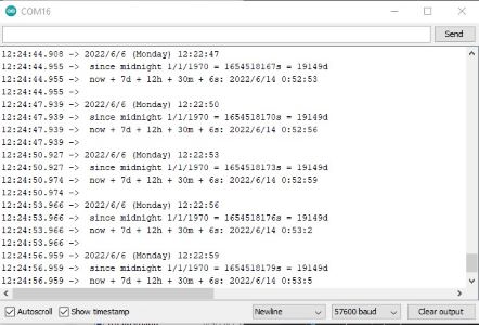
The later pages of the website above lead you through running the example RTC code which is found once you Install the RTC library. You find it at Examples>RTClib>pcf8523. For some reason the first time I ran the code it didn’t work. Then it didn’t work the second time. Then I took the battery out and replaced it and then it did work. So then I was able to see the time/date/etc on the serial monitor.
The example code has 3 different outputs:
- first line is today - the year/month/day (Day of the week) time (in 24 hours)
- second line is the number of seconds and days since January 1, 1970
- third line tells you exactly what it is - now (right now) plus 7 days plus 12 hours plus 30 minutes plus 6 seconds.
Here’s a sample of some outputs: It runs every 3 seconds.
Here’s a short video that incorporates the LCD and the real time clock:
Neopixels
After a few hours looking around online to determine what wavelength light would be the best, I decided to go with Adafruit Neopixels, but packed tighter than the ones we have in the lab. I got these that are 144 per meter. This allows me to use less length to get more light. I have decided that we need 1/4 blue lights and 3/4 red lights to create a broader spectrum light that should serve herbs well. See my week 16 for more info on that. NOTE: in the end these neopixels had much smaller pads for soldering wires. This made it REALLY HARD to solder the wires and made the connections pretty unstable. Next time around I would go for the spaced out neopixels and think about the design so there could be the same number over the plants, in a different configuration.
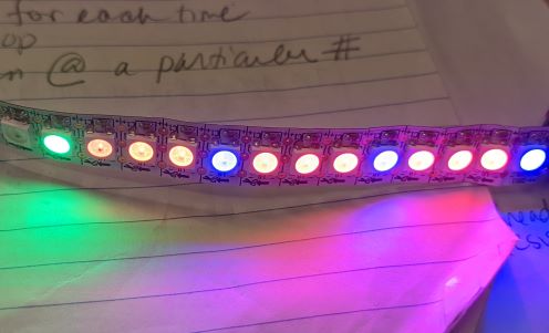
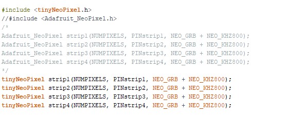
To use Neopixels you need the neopixel library in the Arduino IDE. I had used Neopixels in week 11, so I already had that installed. NOTE: there are different libraries for Arduino Uno vs the ATTiny1616, as described below in the programming section. I had also used modular arithmetic then to program the pixels I was using. So I was able to alter that code. Here is an image of a strip of 13 neopixels. Each plant will have such an array; so in the end there will be 4 such sets. The first 12 are going to be the mixture of blue (1/4) and red (3/4) and the last one will be green if the moisture sensor says the plant doesn’t need water and red if the sensor says it does. You can see how this looks below.
Now since I want 4 strips I need to figure out the programming for that. I had thought I would connect the 4 strips in serial but then I have to run wires from one to the next and I think that might be more problematic than programming 4 different strips. So let’s try that first. I have only cut off one 14-pixel strip, so I hopefully haven’t ruined anything yet!! Haha. And yes, I want 13, but I kept an extra.
I used the following site to figure out how to solder Neopixels to wire. Then I will solder 2 wires together so that each strip can plug directly into my board.
I just needed 4 separate pins to program the individual strips of pixels. Not a problem. This page helped. There is a difference in codes and library when you switch from the Arduino to the board I made myself. That is something to note!! You can see in my code below I have the code for my board ready to go and commented out the Arduino code:
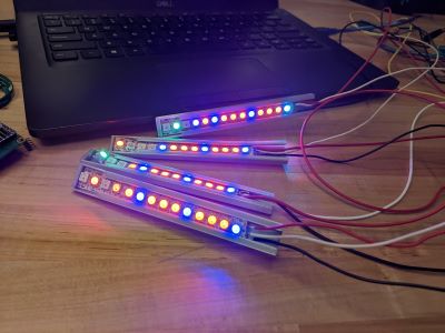
Getting the 4 strands was easy enough. Needed to program the first 12 lights to be 1/4 blue and 3/4 red and then the last light to react to the moisture sensor. You can see the picture of the 4 strips programmed below and then a short video of how the moitsure sensor and lights worked together.
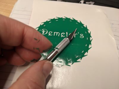
Logo design
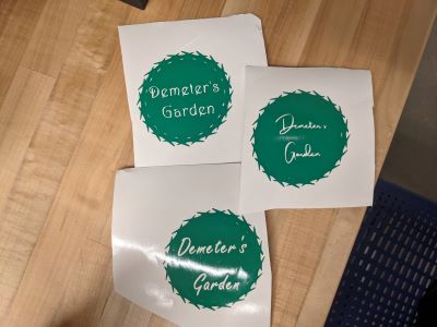
In week 3 I had designed a logo for Demeter’s Garden. I still like that logo - the outside part is like a crown make of leaves - seems appropriate for the goddess of harvest and agriculture, etc. Now I had to decide on which lettering to do I want to use inside. When I made my draft slide in Canva last week I really liked the script of the Amsterdam One font. But Inkscape doesn’t have that font. I went through the entire list of fonts and found Harrington as one option. It is a bit different, but it seems like the best option. I also tried Freestyle Script. I actually vinyl cut all options because I wanted to see how they actually came out, not just look at the screen.
Below is a photo of all three options as well as a shot of me weeding. It’s not a fun logo to weed (as evidenced by the vinyl stuck to my fingers).
Here’s the design file that I created in Inkscape:
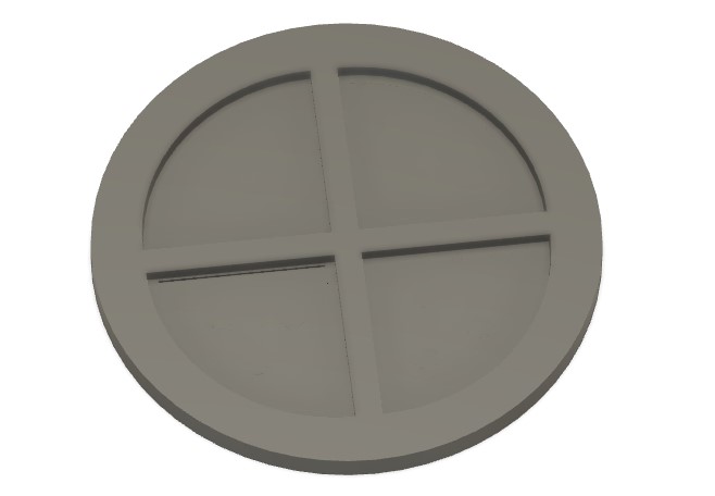
I was originally thinking I would put the logo on one of the pots. All of the pots. None of the pots.... In the end the middle tower needed a top so it seemed the perfect place to have the logo. And I planned ahead with a couple of backup copies so they were ready to go!!
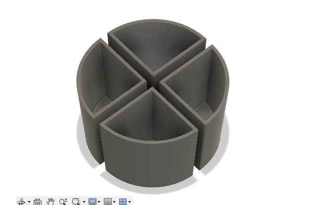
Planter design
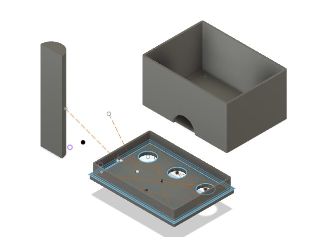
I used Fusion 360 to design all parts of the planter. The main components are shown below with links to their respective Fusion 360 files.
The modular planters (3d printed):
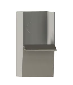
The base of the planter (made of wood using CNC): The planter has pockets for the 4 individual planters and a design that adds a platform beyond the circle for the LCD/button box.
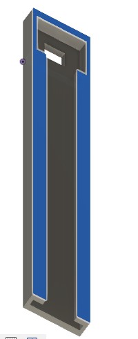
The neopixel and moisture sensor holders as well as the central component to hold the wires (this was a last minute design change because of the wiring of the individual neopixel strands): Note: The neopixel holder has a slot that the neopixels slid through, as well as a “window” on the opposite side so that the moisture sensor light can shine through. I had to experiment with this a few times to makes sure that it was a tight fit, but then the hopening at the end needed to be large enough to pull through and fold over the strand of neopixels for the top one to show through.
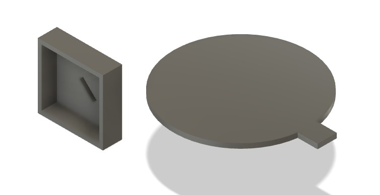
The LCD and Button box and wire covering between this and the object below (3d printed with vinyl cut button labels):
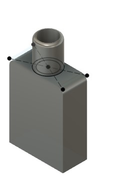
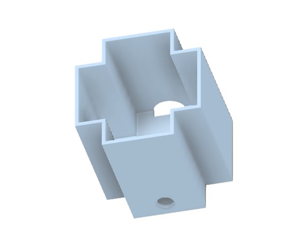
The board and wiring box to fit snuggly between the planters (3dprinted):
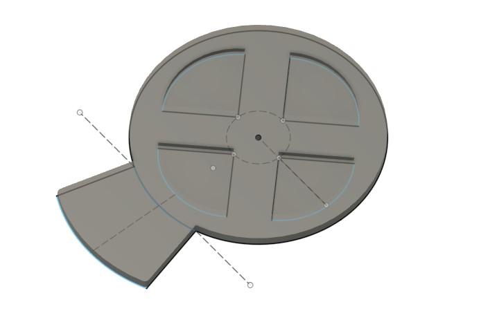
The logo for the top, which also serves to cover the tower with neopixels and the wires inside. (also 3d printed with vinyl cut logo):
Electronics design and implementation
I used KiCad to design my board. I got to the point where I was able to identify what was needed (mostly) to make the board work with all the various components. I ended up using most of the pins on the ATTiny1616 for this project. It was important to pay attention to digital vs analog pins. For instance, moisture sensors are analog bc they sent back a number versus the button pins which only needed to be digital bc they were on or off.
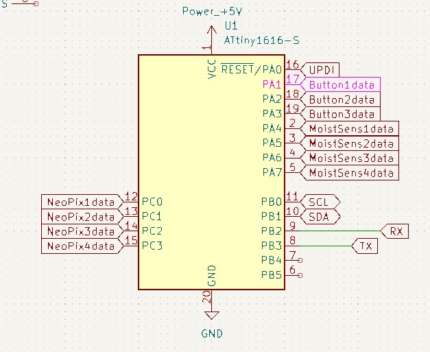
Here’s the schematic.
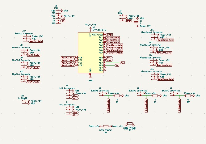
You’ll notice that I defined several components so that they wouldn’t have to be a huge connected mess. For instance, I labeled all the pins of the ATTiny1616 so I could then just use those names for the headers that I needed on my board.
Here I also used through-hole pin headers for all the parts that needed to be connected. I’d never done that before and wondered why when they were MUCH easier than the surface mount ones. I would like to think more about how to space them out so attaching them was easier. I did use a breadboard as I saw suggested in the RTC tutorial I used (linked above).
For this board I created 3 pins for each device: GND, VCC and a data pin. I think this was a bit of overkill. I could have probably soldered wires and/or done some other designs that may have allowed this to be less tediuous. In the end the design was pretty nice. Then I remember that I needed resitors for hte moitsure sensors and then added them on top. A little less ideal.
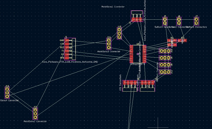
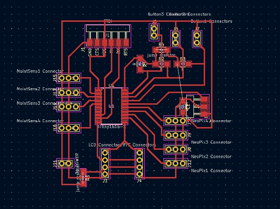
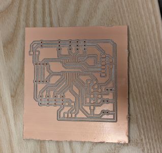
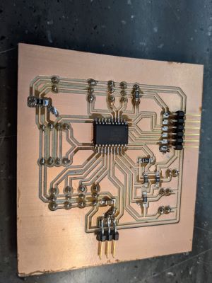
Here are the PCB stages: everything a mess and then the final version with the traces added.
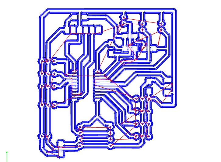
I used mods and then I used the Sainsmart mill, as we have for most projects. Here are the mods traces path, the milled board and the final soldered board:
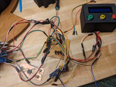
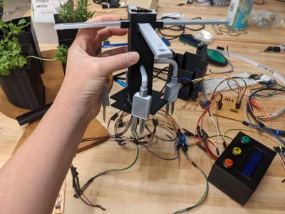
In the end the wires were, of course, a mess. But you can see in the final project above they are all well hidden away in the parts that I designed and 3d printed. Here are some fun messy wire pics!! Again, in a future iteration I’d think more about design of the board and the wirepaths and connections to perhaps minimize the connections and soldering.
Program
As usual I used the Arduino IDE to write my code. I tackled each of the components separately to ensure I could program them. Finally I put everything together and uploaded it to my board! I put comments in the program so you can tell what each part does. I did write some functions to make thing cleaner. Here’s the basic idea of the program:
When the planter is plugged in it runs a welcome message. Then it asks the user to choose a level of light for each of the 4 planters. Then the loop of the program turns lights on at 10am for each planter and off when the appropriate time has been reached. The loop also constantly checks moisture levels and changes the top light to indicate if a plant needs more water.
Here’s a short video of the initial start up with the button presses. Note this is at 4x speed, so you might need to pause or slow down to see it.
A happy upload message when the program is loaded:
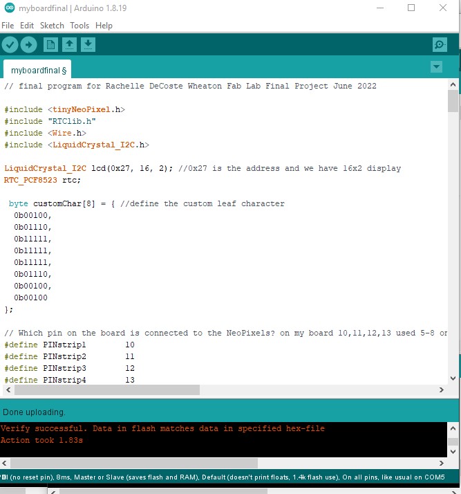
Here is the link to the program file.
Final thoughts
In the end I incorporated MANY different components and am proud of the program that I wrote to incorporate them all together. You can watch the video to see more about the process and you can order your own Demeter’s Garden online soon. Ha, no you can’t. But I may make a new iteration next year when I am on sabbatical.
Updated list of parts:
| Material/Component | How much/many | Source | Total Cost |
| Adafruit Neopixels - 144 per meter - used 4*13=52 | 1 roll | Adafruit or Digikey | $59.95 |
| 5V 4A power supply | 1 | Adafruit | $14.95 |
| 2' x 2' baltic birch plywood | 1 | Makerstock | $47.54 |
| KeeYees Soil Moisture Sensor module (5pack - used 4) | 1 | Amazon | $8.99 |
| Adafruit Real Time Clock | 1 | Adafruit | $6.95 |
| Buttons (50 pack) | 1 | Amazon | $8.99 |
| LCD screen 16x2 with backpack | 1 | Amazon | $11.99 |
| Attiny1616 | 1 | from lab | |
| Watch Battery | 1 | from lab | |
| Black Vinyl | several pieces | from lab | |
| Various colors filament for 3d printer | several | from lab | |
| Wood Stain | from lab | ||
| Total spent | 159.36 |
In the end the machine worked fairly well. I tested each of the 5 components as I was building so I could trouble-shoot before I put it together. This allowed me to have a final product with all pieces working together in the end. I tested it by adding water to the soil to see if the moisture sensor would change. I also decided to add additional output to the LCD that confirmed what choice was made for each plant. One thing I wish I had built into the design was an ease of determining which neopixel and moisture sensor wires were attached to which holder. That was a bit of a confused mess and in the end I was taping groups of wires together, but there has to be a better way.
The biggest issue I had was getting all components working at the same time from the board I made. The wiring was not great and the ATTiny stopped working a couple of times - I replaced it and struggled with the resoldering each time. In the end I made it work but was not convinced it would not be a fire hazard!! One of the worst parts was the neopixels. In the next iteration I Would think a lot harder about how to wire everything. I would probably make some breakout boards to make things a bit cleaner and would think about wiring the neopixels in series. I thought that would be too hard with the original design I Had for the holders, but I ended up changing that at the last minute. I still think it would be challenging to run wires, but that needed to be reconsidered. Also, just the soldering of wires. How could I have designed things to make those wires work out better. Whether I used extension wires or soldered wires together, it always seemed I was resoldering or unplugging and plugging back in. So in the end that was the biggest take away. I think I learned a TON though and the fact that I had never made anything of my own with that kind of PCB board and I made it all from scratch, though it was not perfect, was a huge accomplishment. I actually do wish I had another month in the lab to start over on version 2 because I wonder how I could put it together to make more sense. TBD....
Initial Project Idea
As a professor and a mom my time is limited. Work and family life keep me busy. Some days I dream about moving to a deserted island with a small group of family and friends. There we could live a life removed from the grind of working and with people who share the same values we do. Right now, with all the anti-vaxxers and anti-democracy all around it seems like a dream…
Anyway, in this new happy world, we will need to grow food. So right now I’m thinking about designing an herb grower. The key features are as follows:
- allows for up to n different kinds of herbs to grow in one large segmented “pot”
- stores up energy from the sun to provide solar-powered light sources (or takes in other light sources to be put out as LED)
- the light sources are unique to each of the n segments to allow for different levels of lighting needed by different herbs
- (may go away) there is a sound feature that allows the user to add new songs/readings whenever they want to change the sounds available
Design
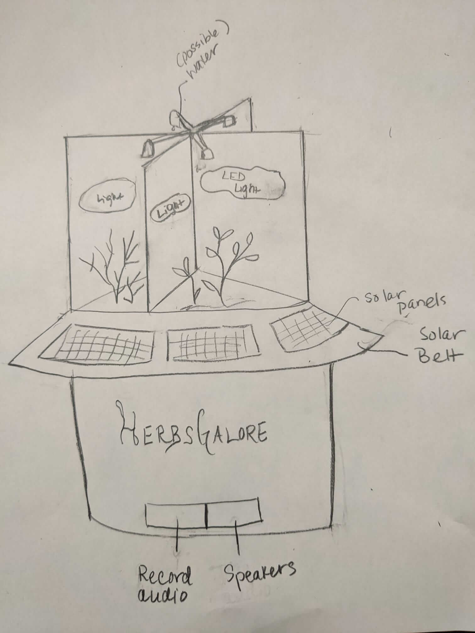
A rough sketch of what the project might look like is below.
Materials
I do not know enough yet to be able to list and price materials. This section will be updated as the project becomes better defined.
At the moment I am thinking about 3-d printing pots, using the CNC to make the base and the sides, and either laser cutting or 3d printing the dividers. In the next few weeks I will work more on prototyping this so I can make sense of how all the pieces will come together and which processes will make the most sense for each piece. I need to figure out more about the electronics so I can incorporate that in a way that makes sense and is well-hidden.
Design iterations
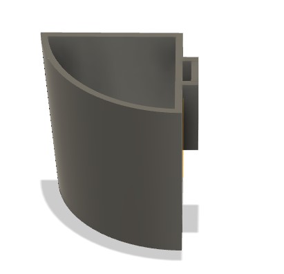
Here’s the idea of modular planters. There will be 2 shapes. Below is one.
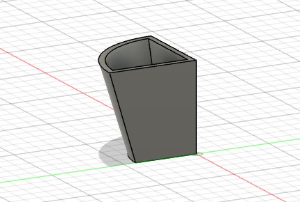 .
.
Here’s an image of the 8-piece modular pieces together. I need to design the base.
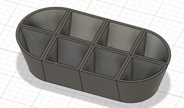 .
.
I attemped to add sides. I don’t like it. Also I was reading that the light should be over the plant, so my original idea to put it on the divider isn’t going to work. Check back here for updates soon.
 .
.
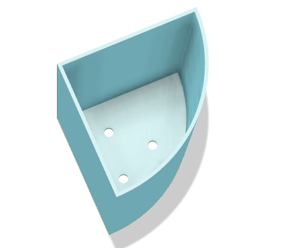
Design updates (May 24 2022)
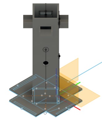
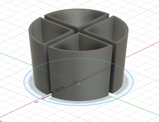
Below are some of the fusion360 screenshots from the latest iteration of the modular planter. For now I’m focused on making a version with 4 pots. They need to have holes in the bottom. They will sit inside a base that is made of plywood, cut using the CNC machine.

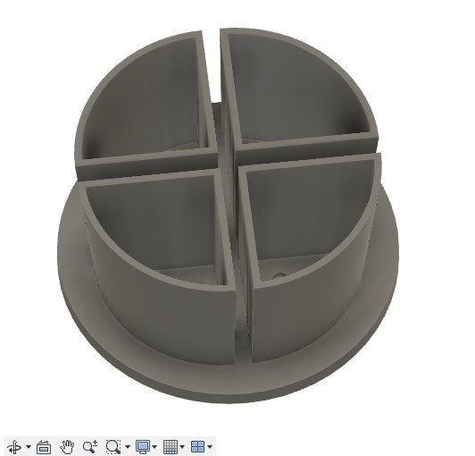
Now with the side holder to hold up the lights:
My own Questions
While this is still a preliminary idea, I want to continue to think about how likely it is that this project will be doable, but also if it will be interested AND satisfy the resquirements of the course. Some of my current questions for myself to consider as the course progresses and my idea becomes more certain:
- Does this exist? And if so, is it ok if I make my own version and design it in a different way?
- Here’s an article on lighting for herbs. It recommends LEDs and has link to some products.
- Here’s a product on Amazon that is hydroponic and has 7 pods.. Mine is different because each herb is going to have its own light source. Also, in mine the number of pots is customizable (in even multiples).
- Another planter with light, 4 pots and Smart Timer.
- Is this really a useful object?
- Can we use solar? How does solar even work? Where is the energy stored and will we learn enough to make something like that work? How much are solar panels?
- Do veggies/herbs have differentiated enough amounts of light necessary? And will LED light be a decent enough substitute for real sunlight?
- What kind of mechanical element would make sense here? Any? What is necessary as part of the final project?
- Do plants really respond to sound? And can I incorporate sound in different ways? Can I include a way to record sound (say a reading from a book or a song) in the final product so that the sound I program isn’t static?
- Is this really what I want to do?? I thought something food related might be cool, but I feel pretty unsure what skills I’ll have and what the possibilities might be in the end. Want to make something that actually works and that makes sense, and of course fits the requirements of the project.