3. Computer Aided design
This week I worked on modeling my final project in various applications of Computer Aided Design (CAD).
Goals for the week
- Modelled experimental objects/part of a possible project in 2D and 3D software
- Shown how you did it with words/images/screenshots
- Included your original design files
Useful links
- Inkscape Official Tutorials
- Inskscape keyboard and mouse reference
- Series of Intro to Inkcape videos
- Introduction to Fusion 360 from Autodesk
- A part everyone can model: intro to Fusion 360
- Hour-long intro to Fusion 360
Inkscape
Inkscape is a vector drawing program, like Adobe Illustrator. One benefit to Inkscape is that it’s free. It has the standard tools of freehand drawing, many built in shapes, text tools, etc. You can save your files as SVG files, but also PNG, PDF, etc.
To start getting acquainted with Inkscape, I watched this tutorial to get a basic introduction.
Then I found some short basic videos by TJFree and watched 1-4 and 6. If you start with the first one you will be able to just continue. I will go back and try to learn even more, but this was all about shapes, colors, etc. I still need to work on alignment and text. I know how to add text, but combining that with shapes for a cohesive output is still beyond me.
Some interesting things I learned while playing with shapes. You can insert rectangles, ellipses and triangles (which also allow for polygons). I tried to work on all three, focusing on the various options and features. They are all in one Inkscape file here
First, there were rectangles. I first created the purple rectangle with the pink border. In watching the videos I learned how easy it was to change the fill color and the border color. The border color is called the “stroke”. You can change both by selecting the object, right clicking and choosing “fill and stroke” to bring open the window. There I changed settings to fill with a pattern (checkerboard here), change the width and style of the stroke and change the gradient of the fill.
When you create a rectangle you have several characteristics that you can determine. Namely you set the dimensions. However, you will also be able to change these later. By selecting the object, when you click once you have dimension tools and then clicking a second time you can rotate and skew, as in the final copy below. Lastly , if you click on the object quickly two times you can change it in other ways. When you do so you on the rectangle, you will see small white boxes on the left top corner and the bottom right corner. If you click those boxes you can just resize the rectangle. You will also see a small white circle on the top right corner. If you click on that and move it around the rectangle, you can curve the corners as you see in the bottom middle rectangle below.
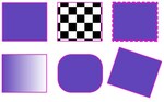
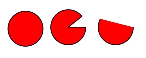
Next I considered circles. I found that the “circle” shape was actually much more interesting and will likely be far more useful than I thought. It makes ellipses and circles. When you insert one, you can change the dimensions at the top of the screen to make it the actual shape you want it to be (fix the dimensions so it’s an ellipse or circle). Then again you have options to edit your object when you create it (or if you have left it, when you double click quickly). You get the 2 white squares and the white circle on the edge of the circle. The squares again change the radii. It’s that white circle that makes this so fantastic! There are 2 options here. If you move the circle while your cursor is outside the circle you will be removing pieces of the “pie” of your object. You end up with something like Pacman. But the real beauty here is that you can specify the degree of how much you would like removed. So here you can make a semicircle or any fraction of a circle. As a math person, I find this SUPER useful. Now, if you hold your cursor inside the object instead you are shaving off part of your circle and basically replace it with a line. You see the outcome of both of these operations in the image below.
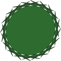
The last main type of shape is a star. Now, one might think, “how useful is a star?!” Turns out VERY. Because in the star option is also the regular polygon option. Once you create a star there is a menu bar at the top that allows you to toggle to a polygon. You can specify the number of corners for either the star or the polygon here. You can skew, rotate, resize, etc, the same as with the other shapes. Now though, the special little white squares become more interesing because when you play around with the inner one it allows for you to drag the spikes of the triangle in interesting ways so that the object can even self-intersect. Below you find 2 images. The top one is just simple playing around with the various triangle options and the bottom is a possible logo for my final project.
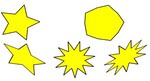
The following is the first go at a logo (no words yet) for my current version of the final project. Right now I am designing modular planters that will have solar power and individual lighting. While with my daughter this weekend, I heard the name “Demeter” in a song from the Percy Jackson musical. Since Demeter is the Greek goddess of the harvest and agriculture, I thought I would name my product something related to that. My daughter has a very large obsession with Percy Jackson and all things related to Greek and Roman mythology. She later suggested that I should use “Ceres” instead, the Roman goddess. I thought the options with the star made for a cool, plant-inspired, crown-like object. That is what you see below. Inkscape file
Some take-aways for Inkscape: * Inkscape remembers the last settings you used. So if you made a rounded corner blue rectangle, the next rectangle you go to make will be blue with rounded corners. I think when you get used to the program you will also get used to getting back to default settings. * If you “save” a file, it will be saved as an SVG file. This is only useful if you want to open it in another vector based program. If you want to use the images you create, export them.
Fusion 360
Some very basic commands/shortcuts: to move around your screen you click the middle mouse button. To rotate your object you need to use the SHIFT+middle mouse button.
I worked through this very short tutorial to get a basic sense of Fusion 360.
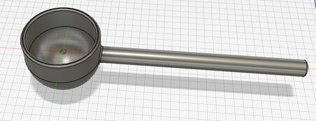
The most useful videos I watched were by Lars Christensen (totally great presentation style). This video steps you through making a coffee scoop. Then I went backed and watched his 3 part Absolute Beginner Tutorials.
I made a basic version of the scoop by watching this video. Fusion 360 file here.
There were some important commands that I learned by working along with Lars. Here are the most useful:
- C makes a circle
- L makes a line
- If you want your line to only be used as a reference for construction, use X after you create it
- E gets you to the Extrude option where you can select the face of the object to be extruded. Here you should pay attention to +/- for the direction of the extrusion.
- F for fillet. I underestimated how useful this command was when Spencer showed it to us in lab. I actually think this makes objects look WAY fancier than with straight edges.
- Shell - this is super useful for my plans for my final project. It allows you to hollow out a solid and end up with the shell
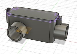
I also watched the hour-long introduction video from which I also learned a lot. I was super excited to be able to construct a really cool output of a device that clamped around a pipe, but the presenter was running out of time and in the end brought in parts that he had already constructed. So I didn’t end up with the final product. I did learn the command Joint which also seems really useful. Also he copied and pasted an object for which he needed 2. So there was a lot of useful learning, but I didn’t end up with the final model. Here’s how far I got. Fusion 360 file here.
In both videos, the presenters used the option to Extrude and object TO a body (include screen grab) which is SUPER useful. Instead of just extruding a certain length, if you extrude to a body, then you are basically attaching 2 objects and moving one later will also make the other move. This seems like it will be useful with parametric stuff later too.
I thought I would watch one more series of videos, so the next day I worked through Lars’s beginner videos, and ended up making this box. Fusion 360 file here.
On to the final project modeling
I learned enough to make a model of the modular pots for my final project. The original idea was a segmented pot that was circular and cut into fourths. Each segment would have it’s own light source, powered by solar panels. The lights would have varying times to be on each day, depending on what plant was in each segment.
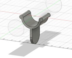
This week as I was thinking about the project I decided to instead design modular pieces. I want to keep the semicircle parts, but then also model more rectangular parts that can fit in between. In this way the planters can be put together however best fits the user. I have modeled the bottom parts so far using Fusion 360. Fusion 360 file with all these steps here.
Though it is not required this week, I decided that parameters would make all of this easier. The ones that I think are necesary right now are:
- height - height of the planters
- potthickness - the thickness of the pots, that will be constant on all sides and the bottom
- botradius - this will be the radius of the circle that defines the bottom of the pot
- topradius - this will be the radius of the circle that defines the top of the pot
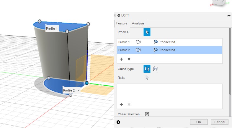
To design the quarter circle, I added a bottom quarter circle using the Arc command. Then I created an offset plane at a distance of “height” away from the bottom one. There the top quarter circle was drawn, with the same center as the bottom one. The command “loft” was used to connect the two regions to make a solid object.
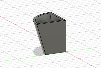
To hollow out the planter, I used the command “shell”, which allowed me to specify how thick I wanted the wall to be. Then the first planter piece was done.
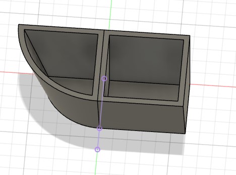
In order to add a more rectangular planter, I wanted the side to match the side of the first planter, so I used the command “project” off the side. Then I could specify the width to be the same as the radius of the circle. These two pieces now fit together perfectly.
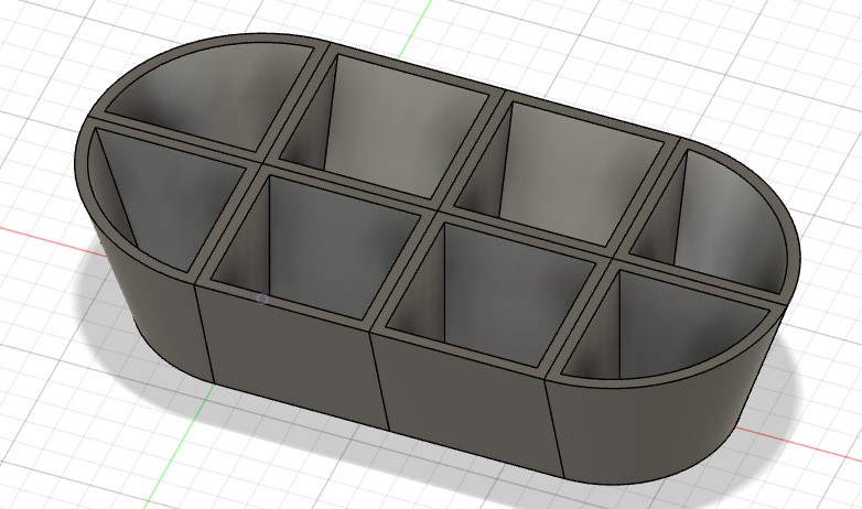
Now we can put as many pieces together as we want to achieve the modular planter we desire. For instance the following. I used the “mirror” command to copy components over various planes.
Now, I still need to model in the solar panels, which will be off the edge of the pot and the dividers, which will contain LED lights. I need to determine how the energy will get from solar panels to the LED lights, so it may be that there is additional space between the modules that is necessitated by these components. More to come....
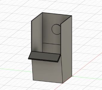
Update Feb 22. Here’s an image of one of the rectangular pieces with the dividers and solar piece off the front. I still need to learn more about electronics to figure out what the design will be to collect solar energy and then send it to the light source.
Also, with respect to the parameters, I need to figure out how to use the 2 different semi circles and get the origin fixed so that when I change the size of the radii the planter doesn’t get all wonky, which is currently what happens - the origins of the circles shift off each other. Need to do some work to figure this out.
Additional comments/difficulties: * You can extrude a face a certain distance, OR you can extrude TO another object. This seems very useful to ensure that if you change dimensions, the extrusion remains the size you want it to be. For instance, the holes in the box above were extruded to the insde of the box. * I am still having difficult with dimensions. Once you have constructed a 2-d cross section of something you should be able to set the dimensions (click D) by clicking on 2 points. Once you’ve clicked your second point, or an edge, you drag perpendicular to the thing you want to specify dimension of. This is hard for me to get the hang of.
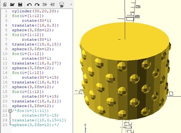
Open SCAD
The only other CAD program I have used is Open SCAD. We used this to design in 2d and 3d this past semester in my Geometry class. The students and I learned the basics and it was pretty interesting to be able to use “for” loops and “if…then” codes. You can do all sorts of mathematical symmetries in OpenSCAD as well as the boolean operations that you have in Inkscape and Fusion 360.
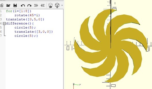
Here’s a very simple design that could be vinyl cut. I should have smoothed out the edges by using the command that lets you set the number of faces for your polygons and polyhedra. Open SCAD file here.
And another design. This was turned into a planter. We visited the college greenhouse and planted a variety of plants in the planters we designed. Open SCAD file here.