11. Output devices
This week we talked about the various kinds of output devices. So many choices! Our task was to understand the options and how to control them with a PCB board. There were questions about power and set up and I hope I have figured out enough to design a new board, cut, solder and program it. Ok, really just the first and last of that list are the goals for this week. I’m going to focus on Neopixels in the hope that it will help me figure out some of the lighting for my final project, where I want to use LEDs to provide fake sunlight for my herbs.
Goals for the week
- Linked to the group assignment page
- Documented how you determined power consumption of an output device with your group
- Documented what you learned from interfacing output device(s) to microcontroller and controlling the device(s)
- Described your design and fabrication process or linked to previous examples.
- Explained the programming process/es you used.
- Outlined problems and how you fixed them
- Included original design files and code
- Included a ‘hero shot/video’ of your board
Useful websites
Group work
Jason walked us through different output devices. We played around with the relationships between voltage, current and power. Basically still trying to understand these concepts. Current is like “flow rate” and voltage is like “pressure”. There is voltage whether or not there is flow. Power=voltage x current (watts=volts x amps).
We need to pay attention to how we construct circuits when we are thinking about power, etc. Note that the arduino limit is 40 milliamps.
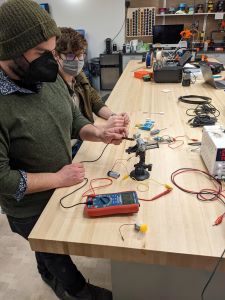
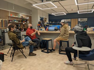
We looked at 2 ways to inspect what was going on with our circuits. One, of course was the multimeter. A 9volt battery actaully sent 8.15 volts according to our multimeter measurement. Here’s Spencer with the multimeter-motor-9volt battery set up.
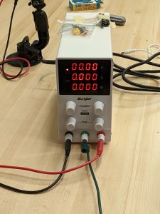
Then we also had the machine below (Kungbar) that measured volts, amps, watts.
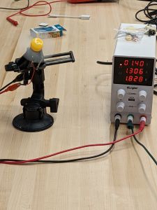
We attached small motors with fans on them to both and measured what was going on. With a small fan we had 1.4V, 1.306 amps which then calculates to 1.828 watts (as in the photo below).
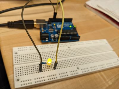
We revisited our blink sketch by making a circuit with the breadboards and arduino. This is a classic example of an output device. Then we altered the blink sketch by incorporating pulse width modulation (PWM). One mistake we made was that not all arduino pins can be used for PWM on the Arduino Uno. Once we figured that out, it worked (the ones you can use have a tilde in front of them). NOTE that the ATTiny1616 that we are going to use can use any pin for PWM.
PWM makes LED grow brighter or dimmer, not by limiting power, but by blinking SUPER fast or slower. The blinking rate determines how bright the LED looks. This needs to happen this way since the LED is either ON or OFF. You can’t send partial power. The part of the code that controls this is the following:
analogwrite(pin, value) where value is between 0 and 255. If the value is 0 the LED is off, 255 is fully on. Any number in between provides partial brightness.
In addition to LEDs, we discussed neopixels (this is what I want to use), stepper motors, which allow you do do precise motion, and servos that are good for rotation, etc. We also looked at speakers, small motors, and LCD screens. When we use these output devices we want to make sure to install special arduino libraries that allow the codes to work. I did this for neopixels (see below).
Jason hooked up the oscillascope again (Sarah and I worked with that a couple of weeks ago).
He talked about the periodic curves and we were able to look at what happened with Garner’s cool code for the LED output He strengthened and weakened the output for the LED and you can see the impact on the wavelengths. I got a short video of that but I can’t it to upload.
Individual work
I wanted to experiement with the Adafruit neopixels.
I added the Adafruit Neopixel library in the Arduino IDE by following directions on this page
I used the simple example code found in the Examples menu: Examples->Adafruit NeoPixel -> strandtest
I followed this tutorial: and set up a circuit with neopixels, a breadboard and an Arduino UNO. I wanted to make sure I understood how this all worked before I tried to create my own board. Sadly I didn’t take a photo of everything in one, so here’s the set of images of Arduino, breadboard and neopixels.
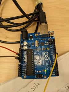
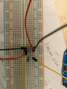
Here’s the image from the tutorial:
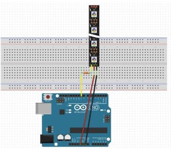
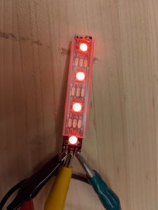
After 3 tries finally got the program to work. I had been using old strips of neopixels in order to not waste new ones. But I Think that was actually the problem. Finally I cut a short strip of 4 neopixels. They blinked on one at a time green. Then to make sure it really wans’t a fluke I changed the color to red. Still worked.
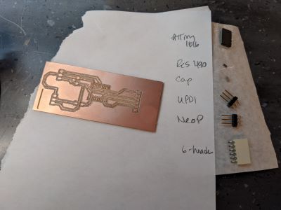
I took that knowledge and went about actually constructing my board.
CPB Board Design
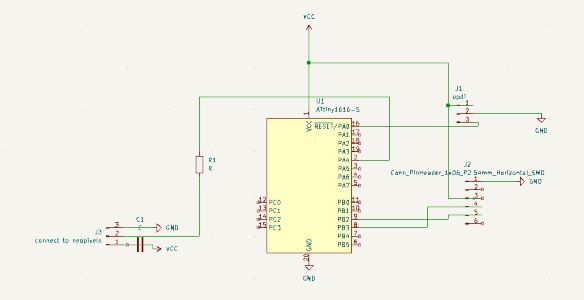
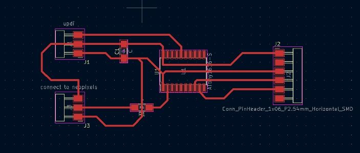
We went back to Kicad to design the new board. This one was a fairly simple design. I used the ATtiny 1616 again. I added a 6-pin header (which I didn’t end up using, but it does make the board more versitile if I want to use it later). I added 2 3-pin headers: one is the UPDI and one connects to the neopixels. So the UPDI one has to connect to ground, vcc and pin 13. The neopixel one connects to ground, vcc and a data pin on the ATTiny. I chose pin 2 (must make it pin 0 in the code bc of the wonkiness of the physical pin numbers not actually matching the pin numbers for programming).
Lastly there’s a capacitor and a resistor. The resistor is on the path from the ATTiny pin 2 to the 3-pin header that is for the neopixels. One resistor works for the strip since it’s a series (vs in parallel). Four neopixels was doable with this set up. Due to the limit on power, I didn’t try to push it with more. Didn’t want to kill my microprocessor before I even started (look back at data sheet and have another conversation with Jason/Spencer about this to get deeper understanding about these limits).
Here’s my kicad schematic and board diagram:
Milling and Soldering
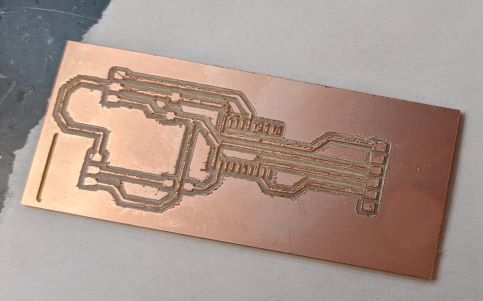
I continue to use the Sainsmart but this is becoming a problem. At first the mill was stuck bc it had triggered some sort of lock/kill. One of last years’ students was visiting the lab and attempted to help fix it. Three hours later I had a milled board. Kevin (the student from last year) insisted that the way we were initializing height was terrible and instead took apart the z-probe and set a height map feature in Candle. This made the process longer - partly bc it just takes longer and partly bc it didn’t work at first (of course). And finally when it did work it actually milled SUPER deep so that my traces ended up really thin (even though I made sure they were set to the right width (.5)). So this was really frustrating. We did check all the traces with a multimeter and determined that it was good enough, but you can see below that it’s not great.
One other thing that happened was that the origin got reset when we tried to do the z-initialization on the outline cut. I had to change the bit so we had to reinitialize (of course bc we use the 1/64 for traces and 1/32 for outline). Then Kevin tried to reset it and thought it was right and then it started cutting into where the traces were. Fortunately we killed it just in time and it didn’t run into the traces. He helped realign this and we ended up with a board. Note: this has happened before that using the z-probe somehow interferes with the wires and triggers a kill switch and then my coordinates are totally messed up.
Twice I was about to give up and use the Roland and then kept getting pulled back into the Sainsmart. Next time I’m going to have Brandon train me on the Roland. Two people came in after me and left before me with fully milled boards while I was still waiting.
Since it took so long I went in early Monday morning to solder. Here I am in the lab around 7:30am. No, I’m not usually at work that early, but it needed to get done.
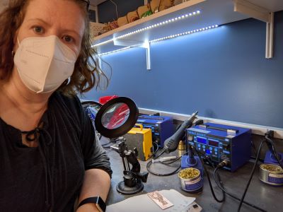
Here’s my soldering set up.
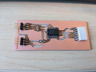
Here’s the final product.
Programming
First, as above, I used the program I found on the tutorial site to just make the neopixels turn on green in succession. Then I made a quick edit to red. Then I decided to make all of the neopixels turn on in a rotation of different colors. This required figuring out how to incorporate modulo in the for loop. That is, because I have a loop with an index going between 1 and 4 I wanted to be able to tell the program to turn on all 4 neopixels at the same time in different colors, so even when the index was 3 I wanted to use all numbers 1-4. Turns out modulo is pretty easy in C++, you just use the percent sign. You can see this in my code in the file below.
It took a couple of tries to get the program uploaded on the board. I used the Arduino IDE and kept getting different error messages. One of the solutions that came up was to change the clock speed. I had no idea if this would work, but I played around with it (Brandon came up with the same idea when I asked him for help). The default was set to 20 MHz. We tried 8 and then 16 finally worked. I got different messages each time I tried a different rate. So it wasn’t a very satisfying answer bc it was not clear what was going on.
Anyway, the first program that I uploaded was just the red lights going, as in the photo below.
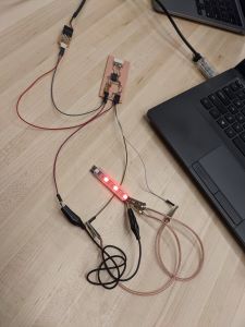
Then I uploaded the rainbow program and got the folllowing video.
Files
- Kicad main design file for neopixel board
- Kicad pcb file for neopixel board
- Kicad sch file for neopixel board
- SVG traces file for neopixel board
- SVG outline file for neopixel board
- .nc traces file for neopixel board
- .nc outline file for neopixel board
- File from tutorial that blinks red
- File that I edited to create rainbow colors