6. 3D Scanning and printing
This week we focused on 3d printing and scanning, though mostly printing. This seems like the topic that most people are already familiar with since 3d printers have become “the thing” in most maker spaces. I have used one previously, but not extensively. I think the challenges involved include how to design objects that can be 3d printed realistically. There are design limitations and I think there is still a lot to be learned on that front. We did some group work that helps us think about this. I also am still working on learning more with Fusion 360. This week I designed two objects that are relatively simple, but I tried out some new Fusion 360 commands. You can read more about that below.
Goals for the Week
- Linked to the group assignment page
- Explained what you learned from testing the 3D printers
- Documented how you designed and made your object and explained why it could not be easily made subtractively
- Documented how you scanned and prepared an object (for 3D printing)
- Included your original design files for 3D printing (both CAD and common format for 3D printing)
- Included your hero shots
Some good and useful links on 3d printing, scanning and Fusion 360 design
- Additive vs Subtractive Manufacturing explained
- 3d Scanning with a Phone with app suggestions
- Learn Fusion 360 in 30 days with Kevin Kennedy
- Skillshare version of the same videos from Kevin Kennedy
Subtractive vs Additive Manufacturing
Last week when we were using the mill, we were using a subtractive process. As that name suggests, we took our material and removed some of it. In our case that was copper. Laser cutting and vinyl cutting are also subtractive processes. You start with an object (cardboard, wood, vinyl) and use the machine to cut out of the material to be left with your design. There are other subtractive processes and we’ll learn more about those later I hope.
The 3d printers we have, Prusa i3 MK3 series, are definitely additive, meaning that you create objects by adding filament to itself. There is no waste here because you are creating and adding, rather than removing.
This page from Formlabs has more information about additive vs subtractive manufacturing. They list the different types of both. In particular the page lists the different types of additive manufacturing. We are using FDM, fused deposition modeling, with PLA, Polylactic acid, a plant-based polyester. According to the Prusa site, PLA is made from corn, sugar cane or sugar beet and is nice to use when you’re starting out with 3d printing.
Wheaton does have an SLA, stereolithography, printer. SLA is a process that hardens resin as it prints. You can achieve totally different kinds of prints from an SLA vs FDA printer. The ones we use layer the PLA from the plate of the printer up, adding material as they go. The PLA we use is vegetable-based, so it’s not toxic, though not recommended for food use because the ridges can grow bacteria, according to that Prusa site linked above. The SLA resin IS toxic. So if we learn how to use this later we have to be really careful with fumes and with skin contact of the resin. There are lots of other kinds of 3d printing out there.
Personally I find the food ones (chocolate anyone?!) super fun and interesting. This is totally not practical in my life currently, but a frivolous and fun application of fabricaion. Here’s a company, Cocoapress, that makes them. Total aside: recently I also learned about laser cutting food, like macarons. Um, so totally cool!! Glowforge has taken over the ad space on my Facebook feed. Clearly I got sucked in.
Group work
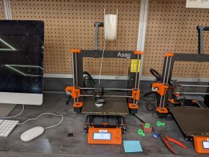
As is the case with any new machine, we have to learn the processes and analyze the outputs to understand both the limitations and the capabilities of the new approach. In this case we were considering Wheaton’s Prusa 3d printers. We have the i3 MK3, MK3S and MK3S+, which are all pretty similar in their outputs. Here’s one of the four in the lab.
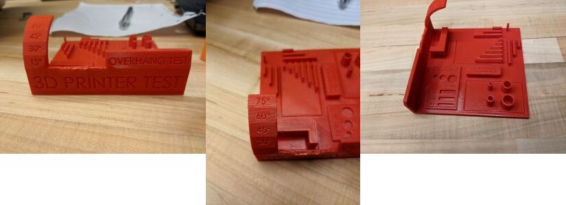
Brandon printed some test outputs for us so that we could measure the actual outputs vs the modeled outputs. The 2 different pieces were a cube and the object below that has a variety of tests: the angle overhang, the bridges, open cylinders, prints that look like cuts into the PLA. Below you will see images of both outputs and action shots of me measuring the cube.
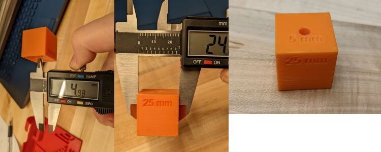
Some intersting observations: all measurements were LESS than I expected, exept in one case. For instance, in the cube which is supposed to be 25mm in each dimension, I measured it to be 24.86mm. This is not far off, but it was consistent with all the measurements that I made. The hole in the cube was designed to be 5mm in diameter, but measured 4.95mm.
In the larger test piece with many different features, the print allowed for 75 degree angle to be printed. This seems like a pretty good reach of what is able to be printed. The longest bridge that was printed was 26.6mm. It wasn’t clear how long that was supposed to be. But I thought this was a fairly long region to be printed with no additional support beyond the 2 ends of the bridge. Four cylinders were printed that were to have diameters of 2mm, 4mm, 6mm and 8mm. The measurements for these were 1.88mm, 3.88mm, 5.88mm and 7.9mm respectively. This was weirdly consistent in being about .12mm smaller than designed. There was a series of holes that were designed to have diameters of 4mm, 6mm and 9mm that measured 3.64mm, 5.99mm and 8.94mm respectively. Of course these are very close and we have to take into account measurement inaccuracy. Lastly I measured the “valleys” that were designed in the object. These were all supposed to be 14mm long, but were 13.85mm. Then they were to be 4mm, 3mm and 2mm wide. Here was the only time the measurements were MORE than what was designed. They were measured at 4.16mm, 3.12mm and 2.09mm respectively. Maybe this makes sense because these are objects that are constructed by their surrounding material. And the surrounding material would be smaller than designed if it follows all the other measurements above. Hm, interesting. Doesn’t quite gel with the different measurements of the cylindrical holes though. Still need to think and investigate some more.
So, end lesson is the the 3d printers we have seem to print smaller than the models. I need to keep this in mind if I’m working on printing parts that fit together. The length of bridging is pretty reasonable (and was fine below when printing hollow objects - more to think about there). The overhang angle is also pretty large.
Workflow to 3d print
You need to create a 3d design in a CAD program. You could find a printable file online, but designing is part of the learning process here. I used Fusion 360 to create my designs. Then these design files need to be saved as STL files. The STL files can be read into Prusa Slicer, the software that prepares the correct file format for the 3d printers. In Prusa Slicer there are lots of options for printing. We learned about some of them, but there are plenty more to experiment with in the future.
To begin with, there are sizing options. The screen of Prusa Slicer shows the bed of the printer that you’ve chosen to use. This helps you visualize how large your printed object will be. The build volume of these printers is 25x21x21 cm (9.84x8.3x8.3 inches).
Before you ask the program to prepare the file, you can select fill options, both percentage and type. The lab has a handy 3d printed sample that shows the various options for fill, as seen below.
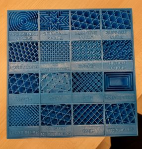
The objects I was printing were meant to be hollow so I didn’t think too much about the fill. I need to investigate further when you would want to change the fill and what the desirability is of the various options. They do seem to provide varying strenths, adn I’m sure fill choice depends on overall design shape and purpose of printed object.
To use the printers
It’s pretty simple to use the 3d printers to print an object that has been prepared using Prusa Slicer. You save the gcode from Prusa Slicer and put it on the SD card for a printer. Once you’ve put the SD card in the printer you can open your file. You need to heat up the bed for the print. You need to choose your filament color and style and load that into the printer. Then the printer just does its thing and starts the output. It is really nice that you can see the updates of how much time is remaining on the print as well as what percentage of the print has already been completed. I found this to be accurate with the 2 objects I printed.
Design and printing of of 3d printed objects
I made 2 different objects this week. My goal was to not only complete the homework but to use Fusion 360 commands that I hadn’t used before to continue learning the CAD program.
One of the objects, printed with white PLA, was designed to be a hollow cylinder with a decorative flower on top. It is not made subtractively because it is a rattle of sorts. I designed it to have a freely moving sphere inside. I accomplished this by adding a post inside and then placing the sphere on top. I added a hole to the side of the cylinder so that I could poke through the side and push the sphere off the post so it would freely move around. This worked!
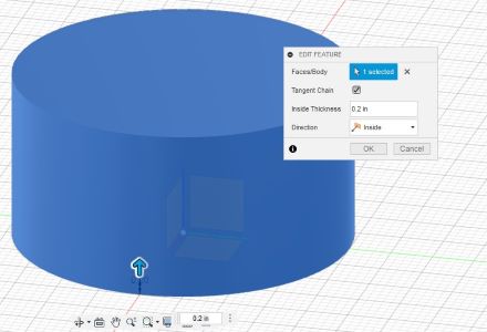
I created the object by first drawing a circle on the xy plane and then extruding it to create a solid cylinder. Then I used the shell command in the modify menu to make the cylinder hollow.
I added a small cylinder attached to the inside of the base of the object and placed a sphere on the top of that post using the join command in the modify menu.
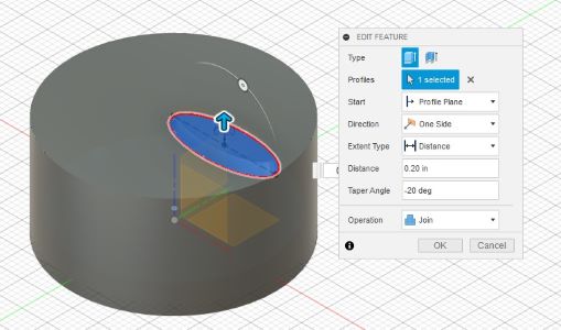
Once the inside had been constructed I added a decorative feature by adding an ellipse to the top of the cylinder. I drew it so that it had its left-most point at the center and its right-most at the edge of the top of the cylinder. I extruded that whole “petal” so that it was a raised feature on the cylinder. When extruding this object I used the taper angle command so that the flower was not just a straight extrusion, but was smaller in the top than the bottom. The taper angle does exactly what you think when you hear taper. Here’s an image of that in Fusion 360.
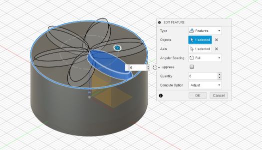
Then I used the revolve command to copy that ellipse so that the collective 6 pieces turned into a flower on the top surface.
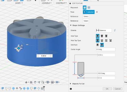
Finally I added a hole in the middle of the side of the cylinder so I could poke the sphere off its post. I used the hole command in the create menu. You see the large number of options for creating a hole of different types in the screenshot below (the green cascading out of the whole and then in the next photo surrounding the inner post).
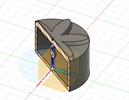
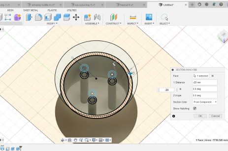
A slice of the final design, using the section analysis option in Fusion 360 follows.
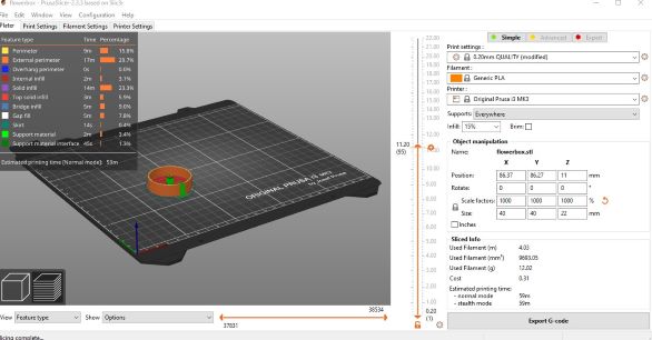
Once I was done with the design in Fusion 360 I saved the object as an STL file to bring it into the Prusa Slicer program that would prepare it for 3d printing. I used the supports everywhere option to see if supports were needed. They were added inside the object around the post that supported the sphere and on the outside and inside up to the hole in the side. You can see these supports in the Prusa Slicer screenshots below. There is a lot of other interesting information on this screen - you can see how much time and material is necessary for the various components on the left side. The right side are all the settings - choose the printer, the fill percentage, the sizing options. At the bottom right you see the “Export G-code” button which allows you to get the correct file type for printing to the Prusa machines once everything else is all set.
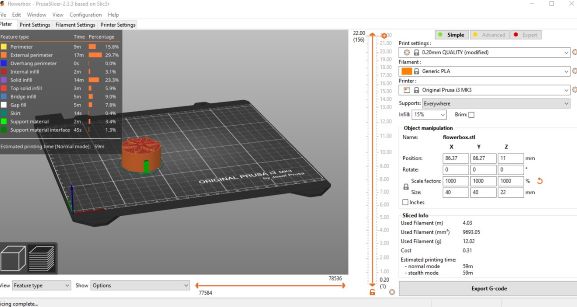
One of the options in Prusa Slicer is the middle arrow that allows you to investigate what happens at the various levels of your print. You can see that in the image below I have moved the top arrow partway down the axis so that we could see mid print.
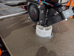
This is the object mid print. You can see the supports and the sphere inside.
Here’s an image of the final product after I removed the outside supports. You can see the small hole on the side.
I was able to use a paperclip to fit through the hole and poke the sphere off its support. This worked great! Next time I should definitely pay more attention to the diameter of the hole and what kind of implement I could use. It took me a while of not getting anything far enough into the object to decide to try a paperclip.
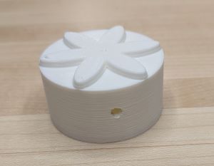
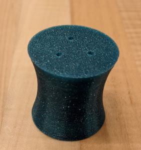
The second object, printed with a shiny green PLA filament, was created using the loft command in Fusion 360. I created 3 offset circles and then attached them. Then I hollowed out the object and added tubes through the middle using the extrude and hole commands. The tubes came out smaller than I would have liked because I resized the very tall object in the Prusa software. So it is hard to see, but they are holes all the way through the object. When you put the object on the table it looks a bit like a salt shaker! But the only place you could get salt in it, without breaking it, are the holes and they go all the way through, so cannot contain anything. And as my classmate said, this is NOT foodsafe, so no food should be near it that is then going to be consumed. Again, need a food-dedicated printer!!
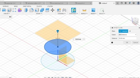
The process to design the object in Fusion 360 started with a circle in the xy plane, centered at the origin. Then I created an offset plane parallel to this one 50mm higher and drew a circle with the same center and a smaller diameter. And then created yet another offset plane 50mm higher than the second one and a third circle also centered over the same origin point on the original xy plane. The following screenshot is the creation of the 2nd plane using the offset plane construction.
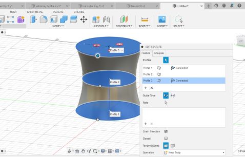
I used the loft command to make a 3d object that connected the bottom circle as the base through the middle circle and then to the top circle as the top surface of the object. Lofting used these 3 circles as cross-sections to create the final outer shape for the 3d object. Here’s a screenshot of using the loft command in Fusion 360. In the end the difference in the diameters of the circles didn’t result in a drastic curve in the object. I was partly trying to keep it reasonable so that the print would work. I wonder if I had made the curve more dramatic and used supports on the outside if it would have worked. Something to try in the near future…
Finally I needed to hollow the object and make tubes through the middle. This is what makes the overall object NOT able to be created through subtractive manufacturing. If the object was solid with the holes through it then it would be subtractive. But it’s hollow in the middle.
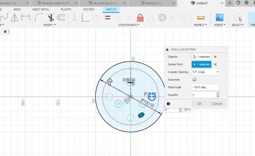
Here I created a pattern of 3 circles on the top surface using the circular pattern in Fusion 360. I extruded the circles and then used the hole feature to make holes through these tubes. You can see the circular pattern options below and then a cross section of the object from the section analysis command in Fusion 360.
After the creation in Fusion 360 I again exported the STL file and brought it into Prusa Slicer to get the gcode for printing. When adding necessary supports here it only added them to the tubes through the middle. That was interesting.
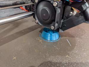
Here’s the object midprint so you can see the tubes being created in the middle of the hollow space.
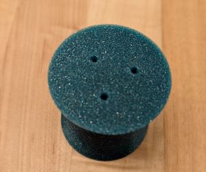
Two different images of the final product are below. I coulnd’t get a good image to show the tubes through the center.
3d Scanning
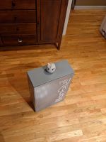
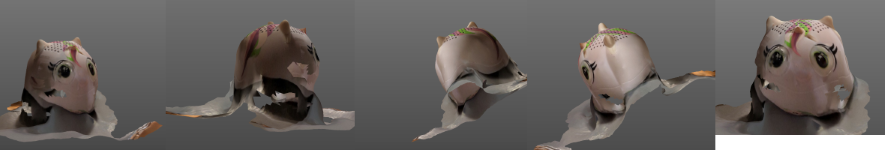
There are lots of free 3d scanning apps out there. As this article showed, most of them are for iPhones. I am one of the few who still refuses to do the iPhone thing. I did finally find one that worked for my android phone. It was the scann3d app. The first time I tried to use it I got a FAIL notification. Then I tried again and it seemed to work ok. One last try on the unicorn bluetooth speaker that my daughter owns and I got a fairly decent scan. Unfortunately this free app does not then allow you to download your scan files without cost. So below you will see the set up for my scan and the screenshots of the output.
Some important points about 3d scanning: make sure you have a space that will allow you to walk around the object. So a kitchen table is not a great option for a small object. I had a large box sitting around that was good for this purpose. Use good lighting. You don’t want shadows around because they will mess with the way the app reads the shape of the object. Take LOTS of photos. I didn’t take enough the first time. Beware the angle of the photos too. I think I took too many from the top. Focus on the object only. In the second try I got too much of the surrounding so the 3d model included all of that and was not detailed enough on the object.
Images below show the set up and screenshots of the outcome. Clearly this would not be sufficient to turn into a 3d printable object. I wonder if MORE photos would make that likely. Probably a better app (probably not free) or actual 3d scanning equipment, vs a phone, would make this a better process also. But I went from pure skepticism about this whole thing to pretty ok results and an interest in learning more. So all in all a good learning experience.

Files
Fusion360 file for the flower cylinder rattle
The STL file for the flower cylinder rattle
Fusion360 file for the “salt shaker” object
The STL file for the “salt shaker” object