9. Embedded programming
This week the focus was on learning to program the CPB boards we had made. My board from week 7 has one LED and one button.
Goals for the Week
- Linked to the group assignment page (still tbd bc of Wheaton Spring Break)
- Documented what you learned from reading a microcontroller datasheet.
- Programmed your board
- Described the programming process/es you used
- Included your source code
- Included a short ‘hero video’ of your board
Group work
Found instructions here. We considered an Adalogger Feather and Adafruit Pro Trinket. Sarah and I worked on this together.
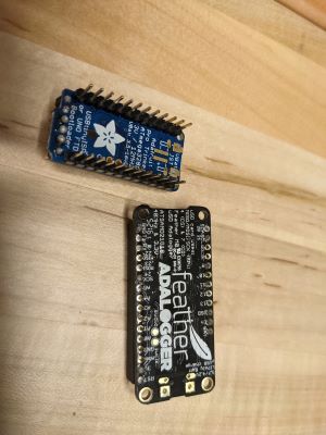
The documentation for the 2 boards led us to the following information.
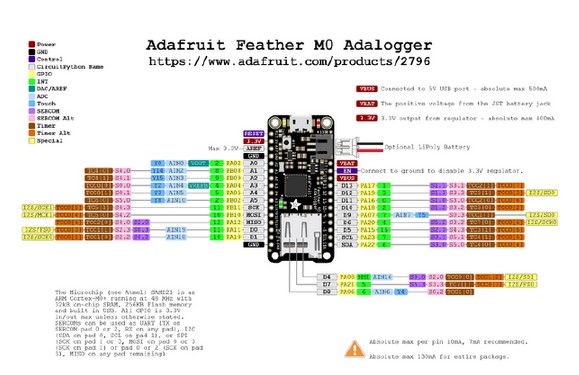
- Processor Family (AVR, ARM, etc): at the heart is an ATSAMD21G18 ARM cortex MO processor
- Bus width (bits): 32 bit
- Clock speed: 48 MHz
- Memory (EEPROM, Flash, and SRAM separately): 256K of FLASH and 32K of RAM
- Number of I/O pins (digital, analog): 8 x PWM pins; 10 x analog inputs
- Logic level voltage (Can you run it off a 3.7V lithium battery? Can you power it directly from a 5V USB port?): has 3.3V logic. connector for any of our 3.7V Lithium polymer batteries and built in battery charging. You don’t need a battery, it will run just fine straight from the micro USB connector. But, if you do have a battery, you can take it on the go, then plug in the USB to recharge. The Feather will automatically switch over to USB power when its available. We also tied the battery thru a divider to an analog pin, so you can measure and monitor the battery voltage to detect when you need a recharge.
- Package styles available (crucially, can you hand-solder it?): You can solder - you can add male or female headers
Pinout:
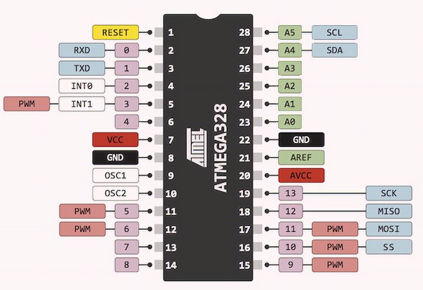
- Processor Family (AVR, ARM, etc): AVR
- Bus width (bits): 8
- Clock speed: 16 MHZ
- Memory in bytes: 32k flash, 1k eeprom, 2k Sram
- Number of I/O pins (digital, analog) 32
- Logic level voltage (Can you run it off a 3.7V lithium battery? Can you power it directly from a 5V USB port?) 5V
- Package styles available (crucially, can you hand-solder it?) yes
Pinout:
We programmed the Feather with blink. When doing this we followed the documentation for the Arduino IDE setup in the documentation. We had to add a URL in the Additional Boards Manager URL option (in File>Preferences). This is the URL: [https://adafruit.github.io/arduino-board-index/ package_adafruit_index.json]. Then in Board Manager we had to Install Arduino SAMD and Adafruit SAMD. I didn’t do this right the first time.
Then it took 3 times for us to actually get it done. Chose the wrong port, chose the wrong Adafruit. NOTE: it was a Adafruit Feather MO Express. Totally missed the MO Express part of the board until the code didn’t work a couple of times. Lo and Behold, when we chose the correct board and the correct port, it worked. The built-in LED on pin 8 blinked!
Tinkercad simulations
Since Wheaton was on spring break this week we had a zoom lab meeting at our usual time. During that session Jason showed us how we could use the Tinkercad circuit option to create virtual circuits to simulate our own so that we could write our programs and then program our boards when we were back on campus with our boards and the necessary FTDI to UPDI cables, etc.
The first thing we did was just create a simple circuit with one LED plugged into an Arduino Uno, port 13, as below.
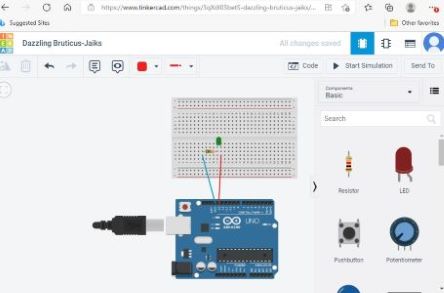
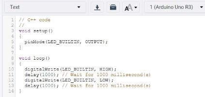
This was the port Jason chose bc there is a built-in “blink” code. It turns out that “blink” is an example program in the Arduino world that simply turns on an LED for 1000 ms and then turns it off for 1000 ms. This is repeated over and over as long as the code is running. Here’s an image of the code.
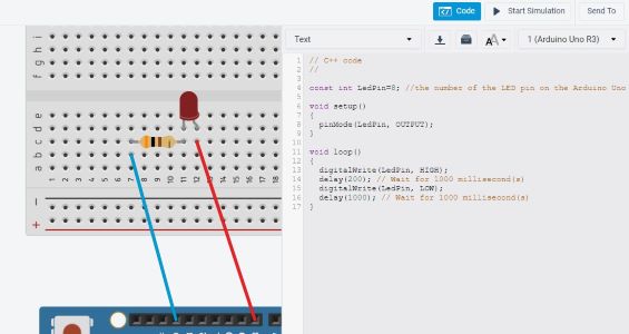
To make sure I understood how this works and to practice with defining variables, I moved the wire out of port 13 into port 8 and then rewrote the code slightly to reflect the change. Here’s an image of this simple code with the circuit.
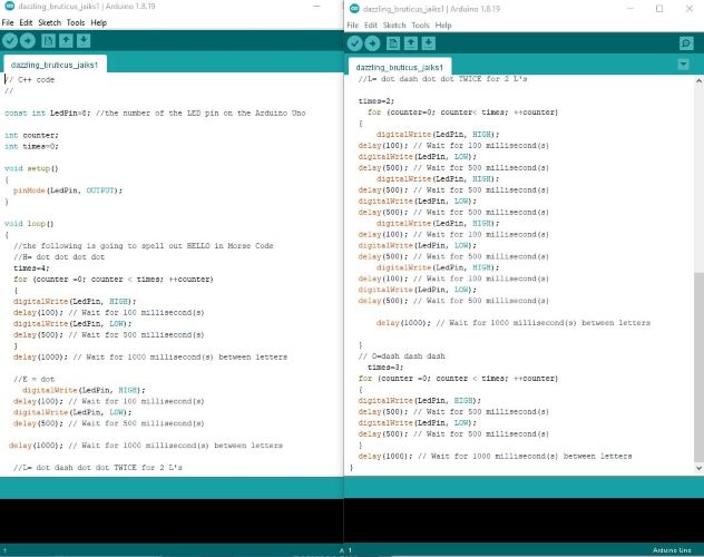
Before I moved on to incorporating the button, I wanted to play around with the programming skills that I have that are SUPER rusty! So I decided to program my button to spell out HELLO in Morse Code. Hello in Morse code needs the letters: H= dot dot dot dot, E=dot, L= dot dash dot dot, O=dash dash dash. Thanks to my son Owen for finding this for me (trying to incorporate help from the kids so they know why Mom is so busy this semester).
So the challenge was to decide how long an LED should be on for a dot versus a dash and do decide the time it is off that is between dots and dashes versus between letters. So I played around with the lengths of the dots and dashes and decided that dot=100ms and the delay between the dots and dashes in the same letter is 500ms. Then dash=500ms and the pause between letters is 1000ms. Next step that I should do (later) is to actually define a variable/function for each dot dash and then just write the letters like that. Instead I just copied/pasted a bunch of times throughout.
Here’s the code that produced this. And I left it with the Tinkercad-given ridiculous name “dazzling_bruticus_jaiks1” and you can find the link to the file at the bottom of the page.
 .
.
And here’s a short video I made with Screencastify (thanks Aimee!) to show the output.
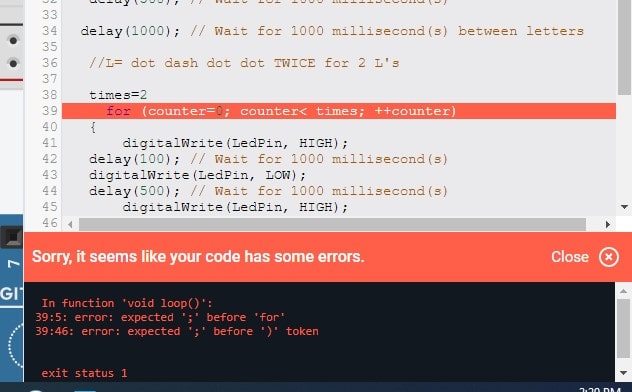
Writing the code in Tinkercad and seeing the simulation is super helpful to do before trying to load the program onto the board to see if it will work. Tinkercad is also great on errors. I forgot a semicolon at the end of the line twice and it gave me an error. See one of those examples below.
 .
.
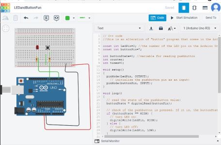
Now I need to learn how to program a button… Going back to my board design from week 7, I reminded myself that the LED was connected to port 2 of my attiny1616 and my button was connected to port 7. I wanted to use the same ports in my simulation so the code would work when I went to program the actual board. I just used the example button code from Arduino IDE and changed the ports. It worked! Here’s a screenshot of the set up and a video of the button pushing (yes, super exciting).
 .
.
If there’s time, I will come back to make this more interesting, but I think for now I have satisfied the requirements and I need to get back to grading my students’ work… I would much rather spend time on this. Some questions I have: can I count the number of button presses? So if I press the button once, the light blinks, but if I press the button twice it just turns on and stays on? I will look into this later. I think this might be useful in my final project to determine how long to turn on light for plants.
ATTiny1616
Here’s the ATtiny 1616 pinout diagram (which I returned to repeatedly during the remainder of the course)
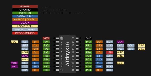
The ATtinny 1616 was super useful. It has 20 pins, with the top left the VCC and top right ground. The pins are numbered as you can see from 1 to 20 physically on the board, but we use the orange/blue numbers for programming (as stated below and as caused problems until I really got it later in the semester). You see that many of the pins are used for EITHER digital or analog data, which creates much more flexibility than the Arduino Uno that we often use as a first round experiement when programming. Pins 12-15 are digital only. Other important ontes for the pins: 8 and 9 are RX and TX respectively. This is important when you want to use serial boards. Pins 10 and 11 are SDA (data line) and SCL (clock line) respectively. These are important when using real time clocks, LCDs, etc, really when using I2C protocols. Pin 16 is the UPDI pin for programming the Attiny.
I usually ended up at the Digi-key website when I was looking for data sheets and this is no different. YOu can find the one for the attiny here. It’s 598 pages long, so NO I didn’t read all of it. Some highlights though:
- Processor Family (AVR, ARM, etc): AVR
- Bus width (bits): 8-bit
- Clock speed: 16 MHZ
- Memory in bytes: 16k flash
- Number of I/O pins (digital, analog): 18 as described above
- Logic level voltage (Can you run it off a 3.7V lithium battery? Can you power it directly from a 5V USB port?): needs 2.7V-5.5V
- Package styles available (crucially, can you hand-solder it?) yes, it’s surface mount
The Attiny 1616 has a tiny dot on the top left corner that allows for correct orientation. It took me a couple of weeks before I actually was able to see it with my terrible eye sight. So the first one I soldered was on upside down. Then I never made that mistake again.
Programming the Board
Now that I have the 2 different programs written, I need to program the board. In fact, I think that it’s just the button program that will go on the board. I also embedded the morse code part into the button sketch. In this program, if the button is pressed, then the LED blinks “hello”. You have to hold the button down for the whole 20ish seconds.
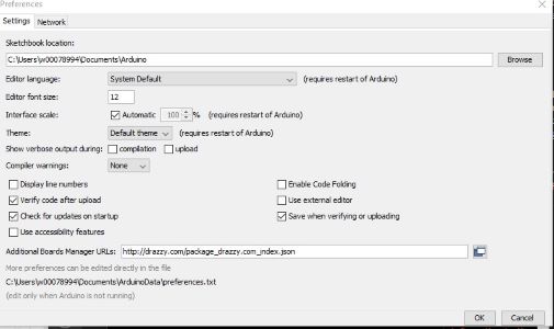
To program the board I need to use the Arduino IDE and an FTDI to UPDI connector. This is pretty straightforward. I did find that I didn’t have the program in the Arduino IDE folder, so I got an error the first time I did it. Then I tried to copy and paste into a new file that was in the right spot (I know bc I opened it from another file that I had used previously and it had all the right board paths chosen). I couldn’t paste. It turns out that Branddon figured out that I needed to go into preferences and uncheck the “Use external editor” option. Then I could edit the file. Here’s a screenshot of that preference screen.
 .
.
And like that it was done. I used the same settings from 2 weeks ago when I made the board. I plugged the board in to the FDTI to USB and it worked.... only it didn’t. Bc I read the pinout diagram wrong. After Jason told us how to read it, I totally forgot and Brandon saved the day again by reminding me that I had used the wrong numbers for my pins. So according to the pinout diagram above I thought I was using pin 2 for LED and 7 for button bc that’s how they are labeled on the diagram below ON the attiny. But you don’t use those numbers! The labels to use in the program are the ones in the orange and blue column. So I had to change them to 0 and 5, respectively, and then it really did work!! Below is the video of me pushing the button and the light going on!! (still need to figure out how to include small videos so they are actually small…). NOTE: June I’ve figured this out and done it on later pages (for instance see week 14). I also do not currently have a video of the morse code with button bc my board broke.
 .
.
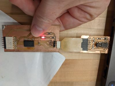
Updates: June 2022
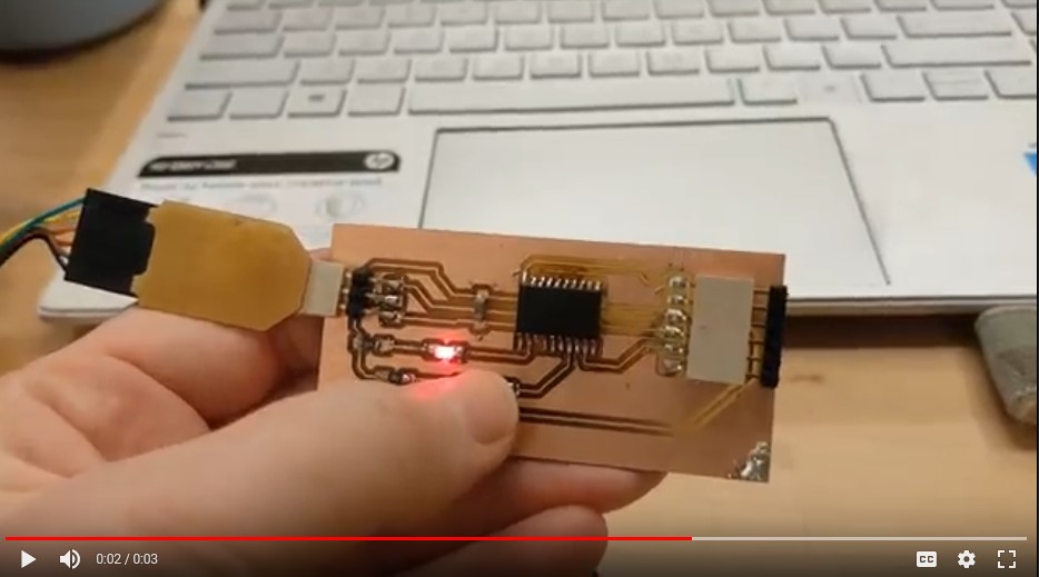
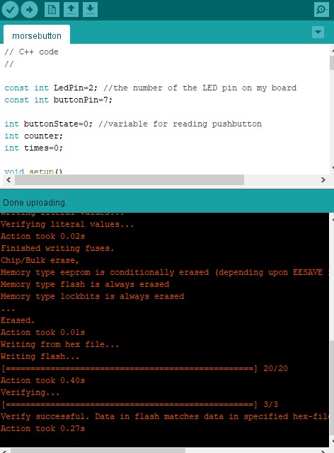
I fixed my button board and I finished my programmer. So I was able to upload the morsecode button program to my button board with my programmer and make it work. Here is the evidence that it uploaded:
Here is the photo of the set up with the LED on and a video of the morse code button program working (video is at 4x speed):