12. Input devices
We’ve actually already looked at input devices. A few weeks ago we used buttons and in our group project we used a series of 3 buttons to move among coffee selections and then to choose a coffee flavor for our coffee carousel. But now we are moving towards different kinds of input devices and hope to use some that will help in our final project. I decided to focus on light sensors.
Goals for the week
- Linked to the group assignment page
- Documented what you learned from interfacing an input device(s) to microcontroller and how the physical property relates to the measured results
- Documented your design and fabrication process or linked to previous examples.
- Explained the programming process/es you used
- Explained problems and how you fixed them
- Included original design files and source code
- Included a ‘hero shot/video’ of your board
Group work
In our weekly lab Professor Jason Goodman introduced us to input devices and the wiring necessary to make such things work, along with some code hints.
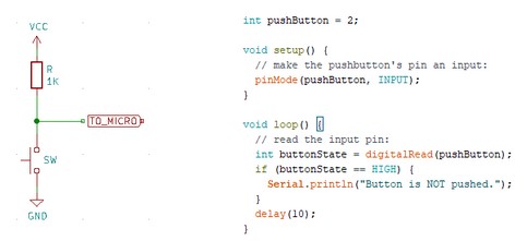
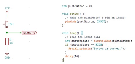
We talked about pull up vs pull down resistors and where the sensor was in relation to the microchip connection and the resistor. Jason gave us the following images for these digital buttons.
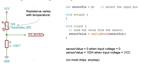
Then we talked about how often digital isn’t good enough, so we need analog inputs where the input isn’t just on/off, but a range of readings. Here’s an image and code to go with that, from Jason again:
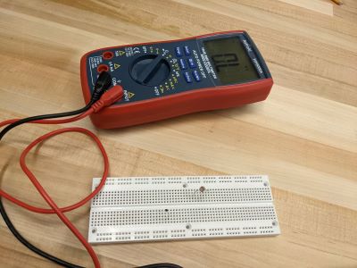
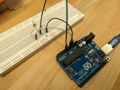
We hooked both a temperature and a light sensor up to a breadboard in order to be able to experiment with them and understand how things worked. Before we coded anything we just used a multimeter to try to understand the range of outputs for both sensors.
For the light sensor we found that the light with a flashlight read 1.3 kohms, with normal light was 3.5 kohms and with a hand over it (so darker) was 16 kohms. This may not exactly gel with my intuition. The less light, the higher the readings. The same with the thermoster. It read 10.6 kohms just sitting there, but then when someone applied body heat (hotter than the ambient temperature), the thermoster read around 8 kohms.
Here’s the set up with the multimeter:
These readings helped us decide on the size of the resistor we needed when we used the breadboards to take readings. We wanted to set up circuits like in the image above. We were instructed to use a resistor that was about average for the readings. So we used the light sensor and a resistor of 10k ohms.
We then used the serial monitor to read the output from the light sensor using the example Arduino code.
Individual work
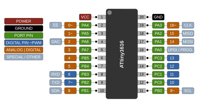
We are again working with the Attiny1616. Now the pinout diagram is again helpful to determine which of our pins have analog function. Below you can see this is nicely diagrammed and limits which pins I can use for input devices. For design purposes and ease of traces, it looks like maybe 2-7 and 10-11 might be easiest? But who knows bc I have to get into KiCad to figure this out.
While I would like to think I am at the point where I know enough about PCB boards and milling and soldering and programming that I can just get this done, I know I’m really not.
I do feel much more confident in my electronics understanding and my programming after the work I did on the group project though. So lets hope that does help.
Creating input board(s)
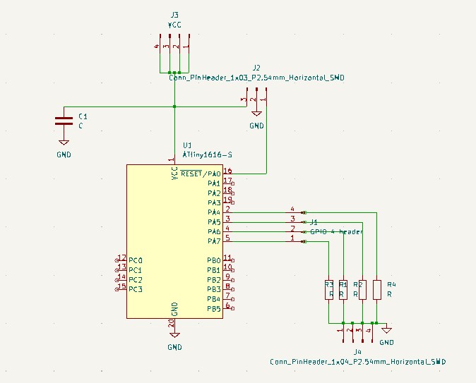
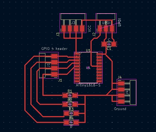
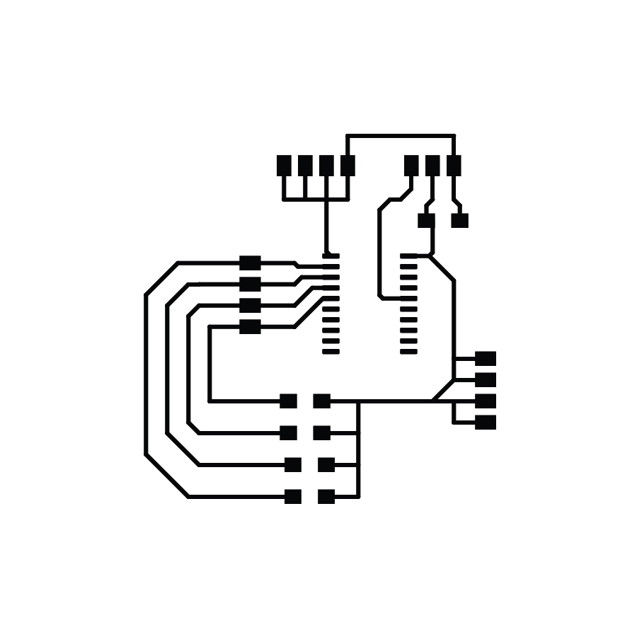
I decided to try to make a general use PCB board. This was created in KiCad with 4 VCC pins, 4 Ground pins, 4 general use input/output pins that run through 10k ohm resistors on the way to ground and the UPDI pins. We are still using our Attiny 1616. I thought this was actually quite a nice board. Here’s the schematic and pcb for the general board:
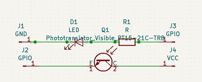
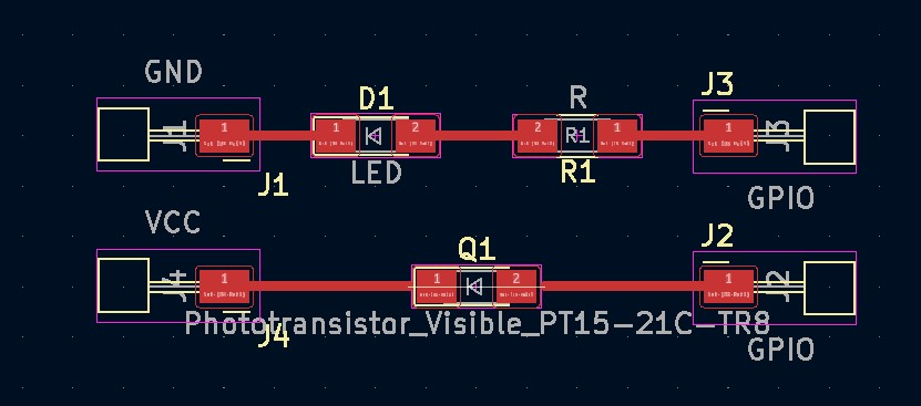
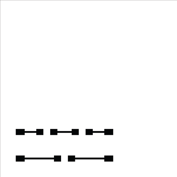
Then I made a small “breakout” board with my photoresistor: an everlight PT15-21C-TR8 and a red LED with a resitor (499 ohm) for the LED. The idea was that I would be able to make a few of these boards and then put light sensors and LEDs in different places. NOTE: yes, I totally anticipate that the LED could then impact the sensor reading. In the real world, obviously this set up isn’t great. But I was testing here to see if the light sensor would read when I covered it with my finger and then blink the LED on. Here’s the schematic and pcb for the breakout board:
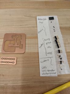
Here’s my situation for soldering and my milled boards:
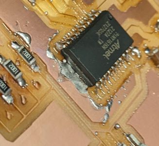
I should note that I milled the boards using the Roland for the first time. The files are below. Brandon Witter helped me with the process for the Roland. He showed me how to make the outside of the board using Adobe Illustrator and then we went through the MODS process with the correct Roland settings. In the end the traces are all a bit thin (even though I designed them for 0.5mm). Brandon thinks it was because of the height of the z-axis. I guess both mills aren’t great at figuring out where you should actually zero the z-axis. A bit frustrating. This was definitely faster and makes a much cleaner board. But the thin traces really made attaching the Attiny HARD!!
Two days later: nope. I can’t get it to work the way I want it to and I’m very frustrated because I just feel like I’m not able to understand. I keep making mistakes.
In the end the 2 boards didn’t work together. I think I need to go back to the soldering of the attiny1616. The errors I got when I was trying to program the chip seemed to say there was an UPDI problem.
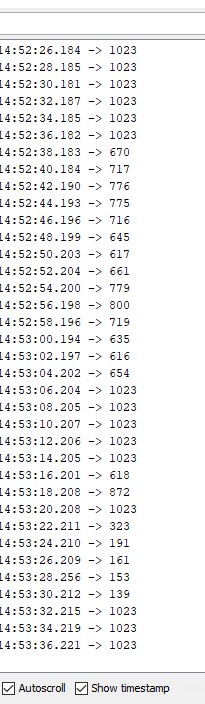
I did manage to get the breakout board to work with an Arduino Uno. Below are images of the change in the light readings (note: readings are just 0 to 1024, so don’t have actual measurements, just the range) and then a video of the LED going on when the sensor reading goes below 1000.
Programming my board
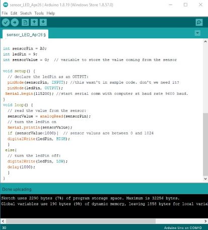
While my general board wasn’t programming, I know my code worked because I got the Arduino Uno to connect to the breakout board to do the right thing.
The program that made all this happen was a simple Arduino .ino file that I started using as the example from the library and then altered with the if loop to turn the LED on. Image below and link to file at the bottom of the page.
UPDATE: It turns out that I just didn’t have my ground pin soldered well enough at the ATTiny. Jason reminded me how to use a multimeter, so that showed Ground wasn’t attached. A quick bit of solder added to that pin allowed everything to work.
I was able to upload the program and the connection to the breakout board worked fine. The photoresistor seems rather finicky.
Some questions that remain:
- If the sensor is taking readings every few milliseconds, does the program just blink the light for that reading and then it takes in the new reading. I mean, yes, that’s what the program does. But how will I keep the light on. I should look into scheduling the readings if I am going to use this in my final project.
- for my final project I’m thinking about using light sensors to determine if the different sides of a modular planter are in the shade. I would rotate the planter to give all parts time in the sun. Going to have to figure out if shade is enough to get lower light readings. I had to really cover the photoresistor to get the readings to go down. Maybe a different resistor will be necessary for the final project.
Files
- Kicad schem for general board
- Kicad pcb for general board
- Kicad schem for breakout board
- Kicad pcb for breakout board
- png for general board traces
- png for general board outside
- png for breakout board traces