COMPUTER CONTROLLED CUTTING
This week I used the vinyl cutter and laser cutter to make a parametric press-fit construction kit.
What is Computer-Controlled Cutting?
Computer-controlled cutting is a subtractive manufacturing method in which computer-generated instructions tell a machine how to cut a material. I used two different machines for this week, a vinyl cutter and a laser cutter. For each, I prepared CAD drawings, which I imported into special softwares that sent cutting instructions to a machine.
This week's assignment came in a a few parts:
- cut something on the vinyl cutter
- characterize your laser cutter's focus, power, speed, rate, kerf, and joint clearance (in groups)
- Design, laser cut, and document a parametric press-fit construction kit that can be assembled in multiple ways
Vinyl Cutting
My group and I designed a team logo to make on the vinyl cutter. Our group name is "Come on Eileen" so we found a graphic of a record player from this site, and added text to it in Illustrator.
After saving this design as an SVG file we opened it up in the vinyl cutting program, Sure Cuts A Lot. This program is installed on a computer attached to the vinyl cutter, so I'm only able to use it in the Fiber Lab.
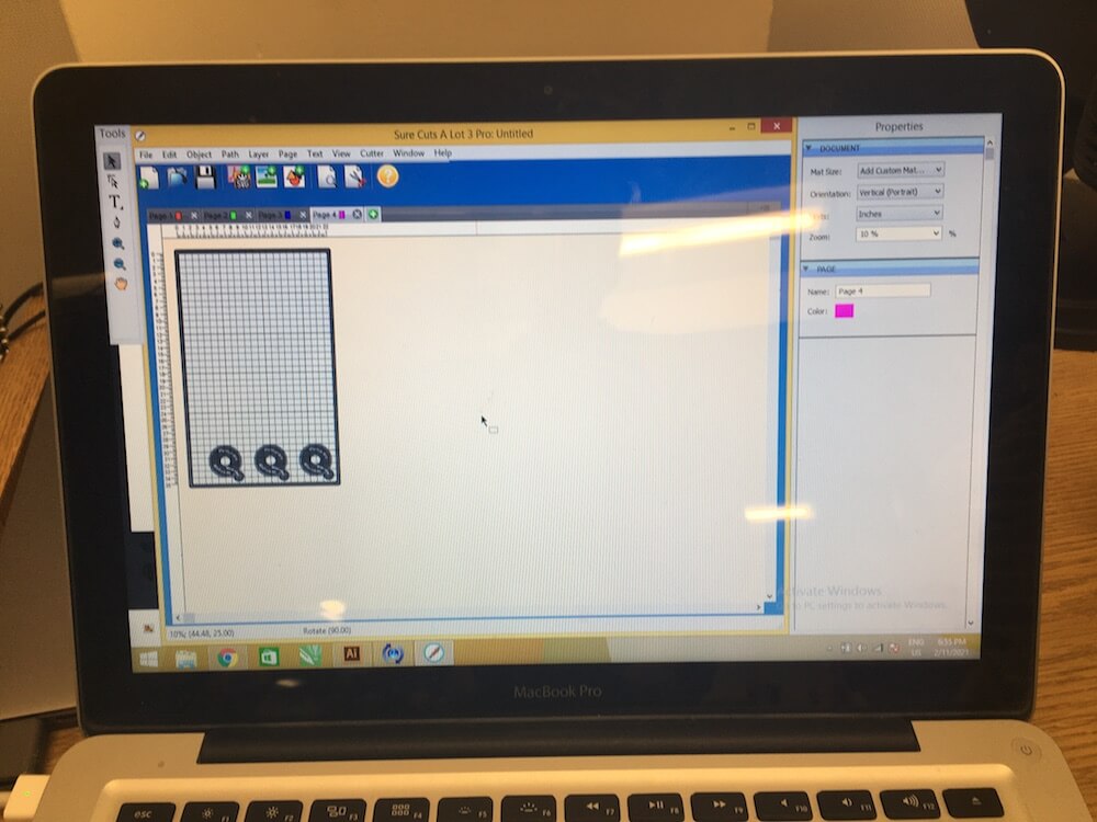
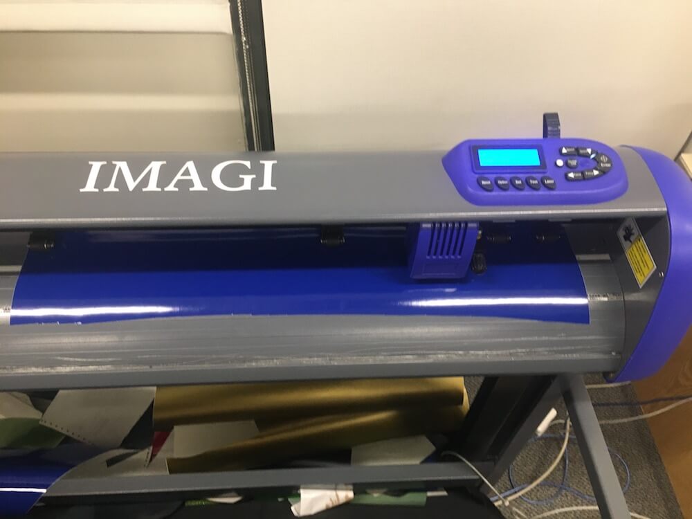
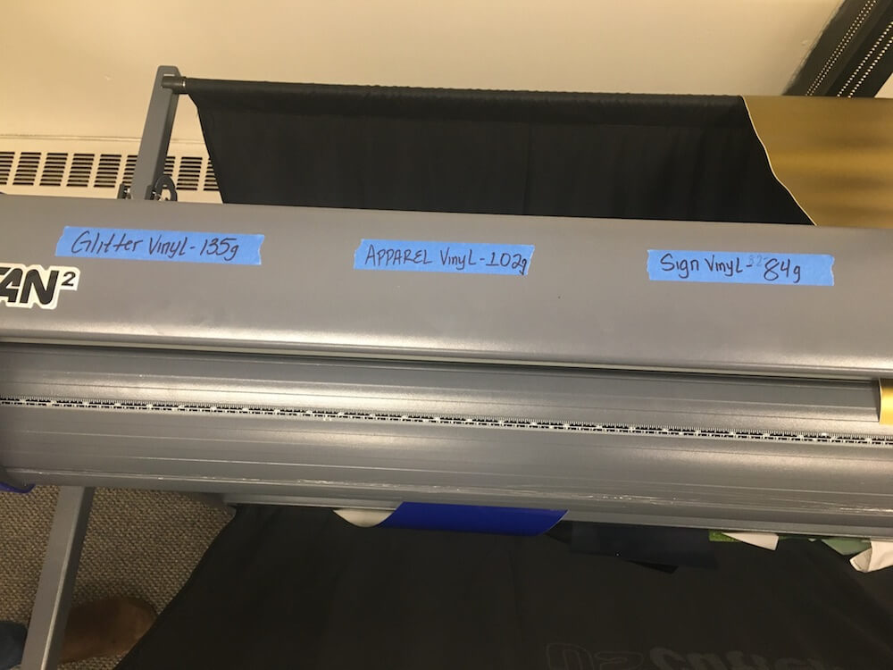
In the Lab, we have a sticker vinyl and two kinds of heat transfer vinyl, apparel, and glitter. These all require different settings for the pressure required to cut through the material. To set up the machine we went through these steps:
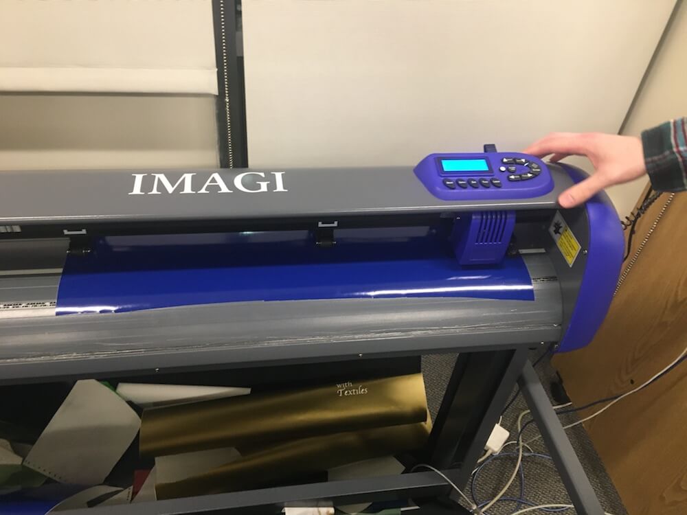
- Inserted a reel of sign vinyl and secured it to the cutting area with multiple rollers, using the handle on the right to clamp it down.
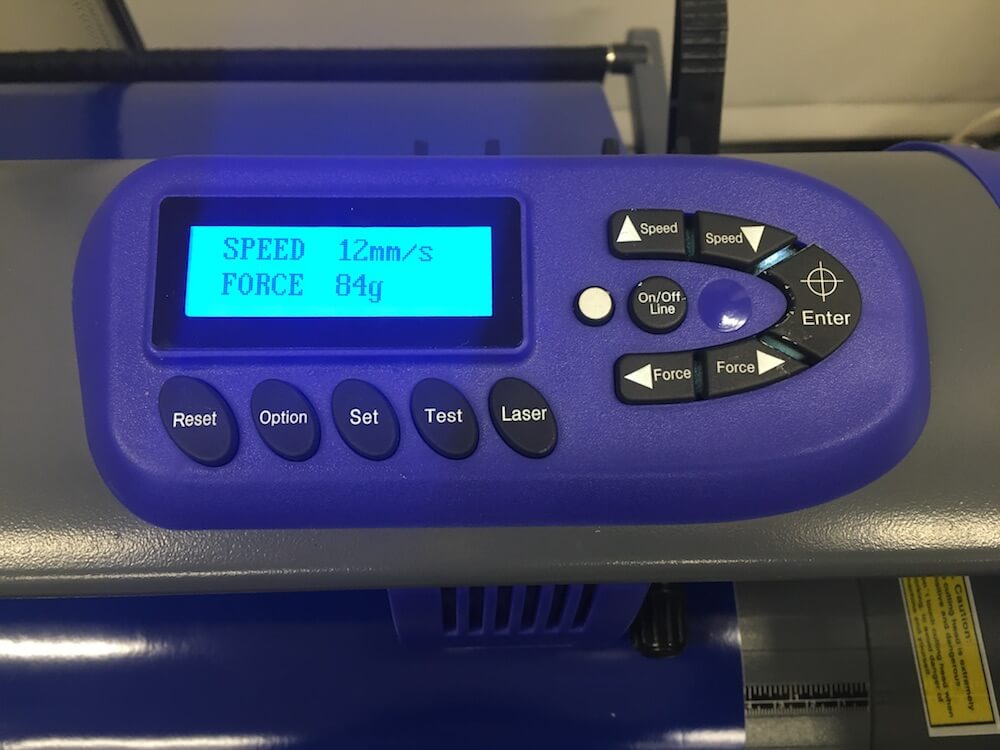
- Entered the pressure for sign vinyl, 84g, using the Force buttons.
- Moved the head of the vinyl cutter to the lower right-hand corner, using the Speed and Force buttons.
By the way, the 'On/Offline' button lets us toggle between entering the force and moving the cutter head.
Next, I cut my section of vinyl off of the reel and weeded it. Weeding is the process of removing unwanted vinyl. I had to be careful about only peeling away the parts that I didn't want. After that, I pressed a piece of transfer tape over my design. This helps to apply the vinyl without getting your fingers on the sticky side.
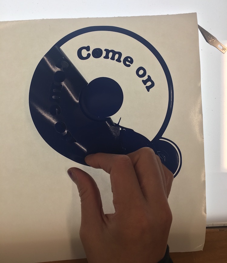
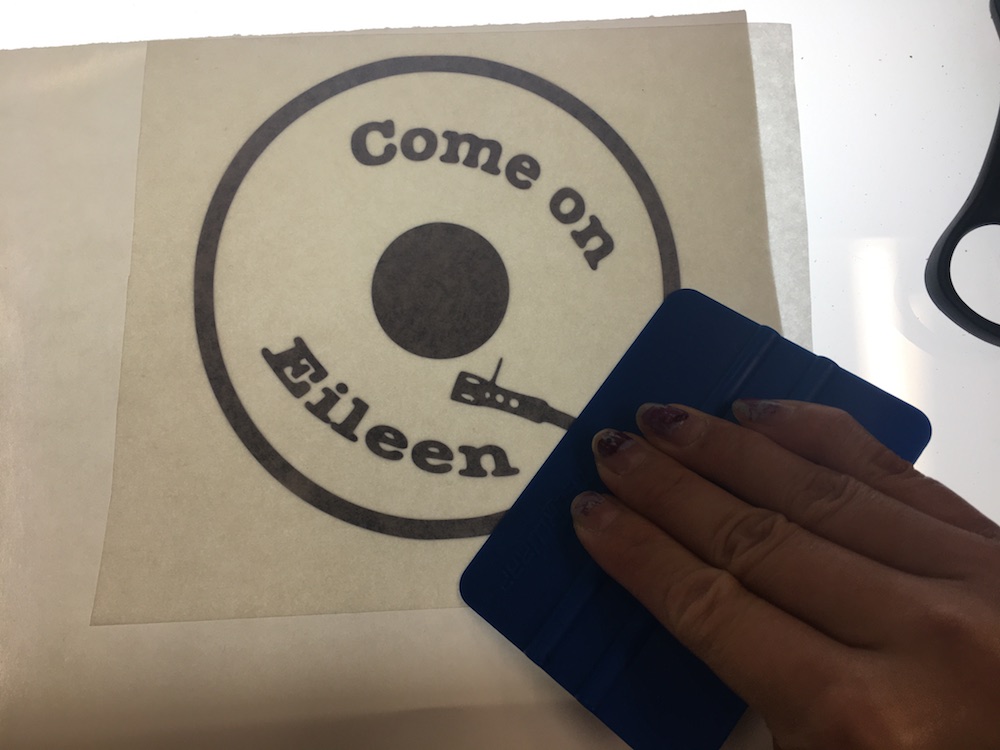
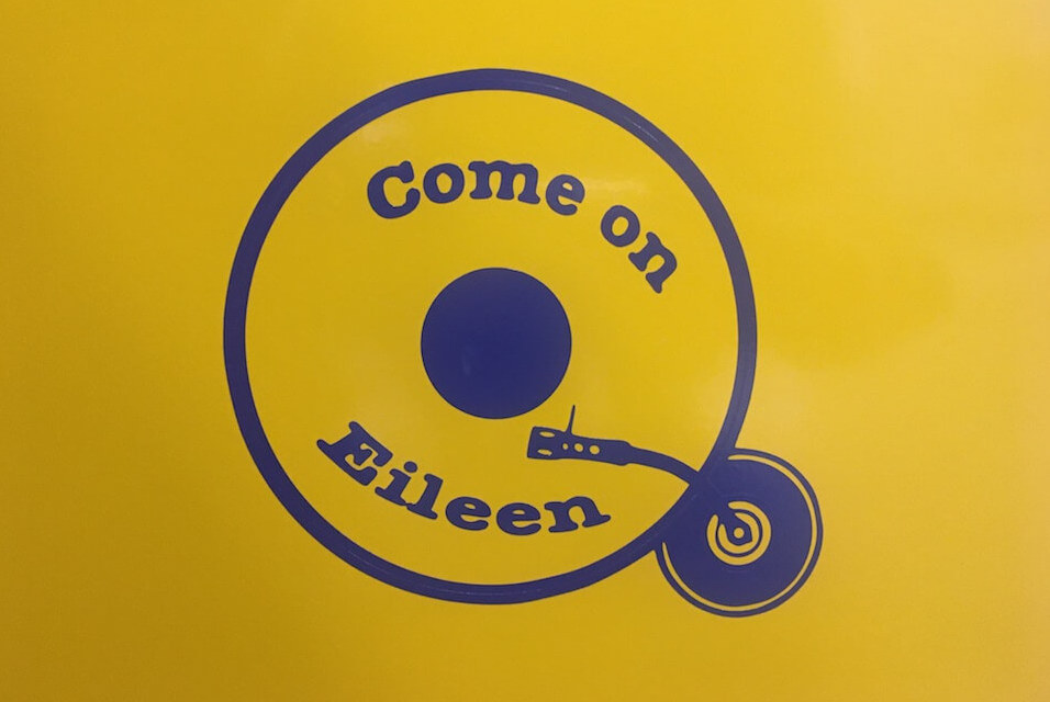
Finally, I removed the backing and applied it to a surface, while making sure to scrape it so there weren't any bubbles.
Group Laser Cutting Tests
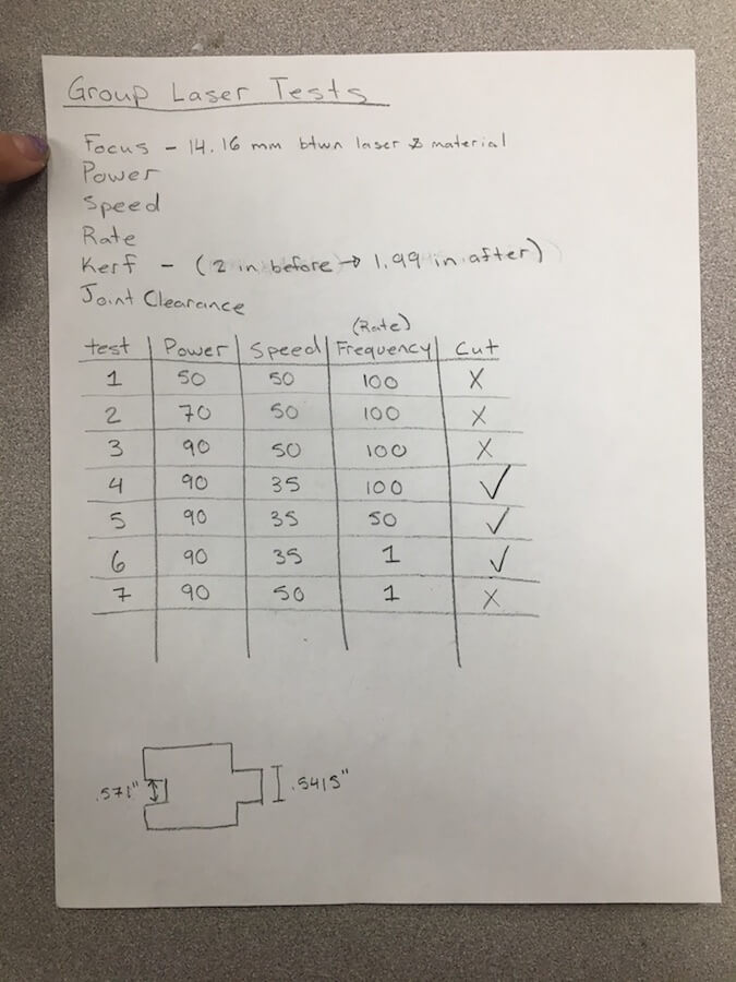
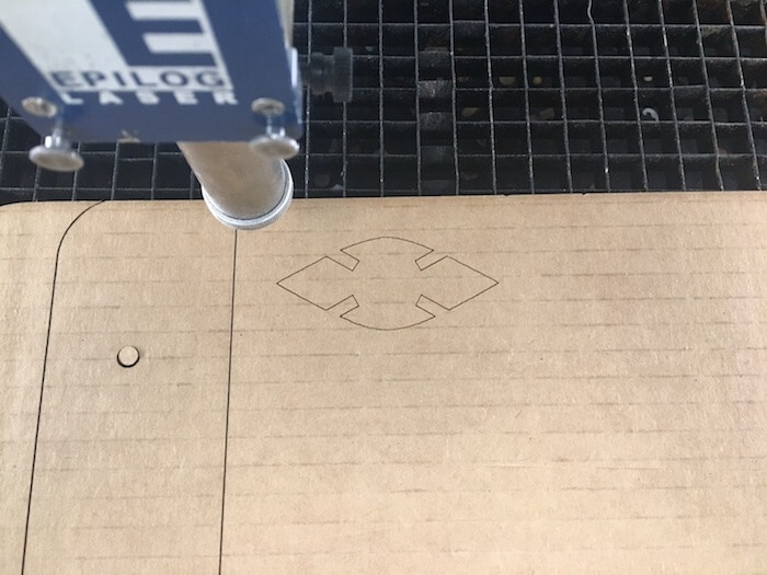
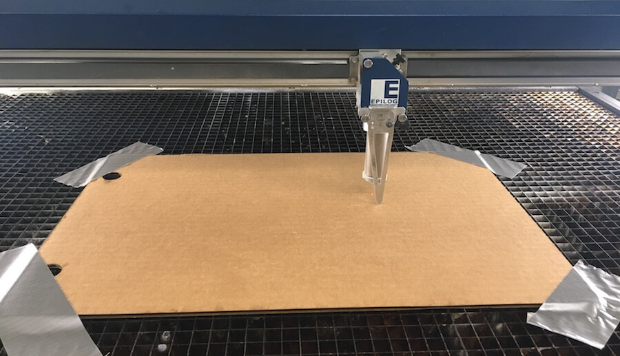
The laser cutter in our lab is an Epilog Laser. In my group, we created a test file, which we cut multiple times to assess the focus, power, speed, rate, kerf, and joint clearance of the machine.
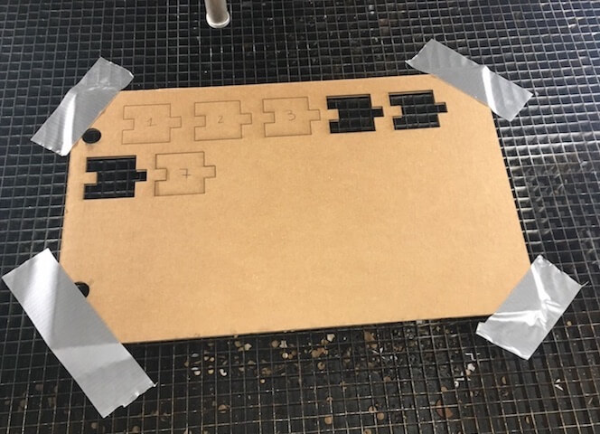
We found that the best settings for cutting cardboard were with the power at 90, speed 35, and frequency 100. If the power was too low or the speed too high, then it wouldn't cut through all of the way. Also, I think something might be wrong with the frequency on our machine because the cardboard was able to be cut at 1% just as easily as when it was at 100%. Our cut pieces had joint clearance, and we think the kerf is pretty small, less than .1 in. Lastly, the focus was fixed for all of the tests because we use a tool to help set the bed height at a certain distance from the laser.
Construction Kit
For the parametric construction kit I was inspired by these images from a pop-up card company and a past FabAcademy website by Hiro Tanaka.
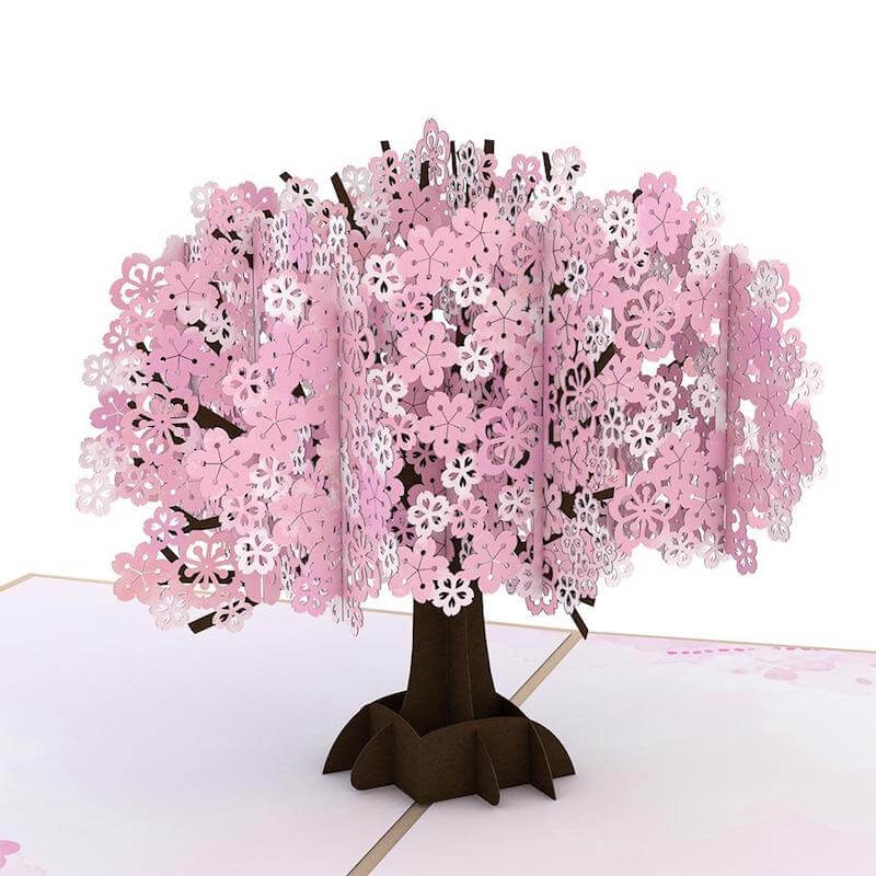
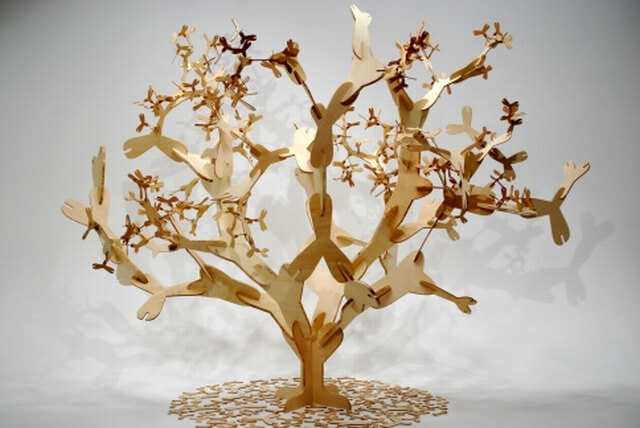
Parametric Design
Parametric design involves using parameters, or rules that define certain aspects such as height and width. They can be used to edit the design easily by entering new parametric values, instead of redrawing a whole design.
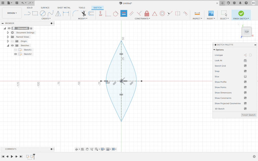
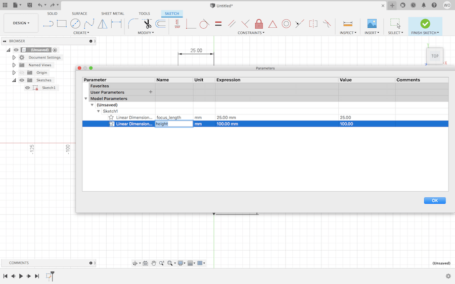
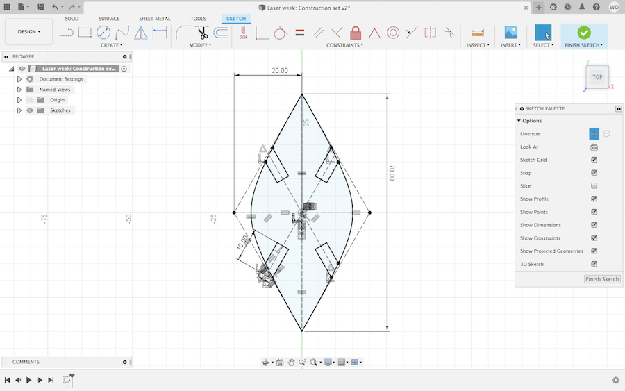
I started out in Fusion 360, sketching a leaf shape. Notice how the outline changed from blue to black. In Fusion, this happens when a sketch is fully constrained. The constraints I mostly used were the equal, horizontal/vertical, perpendicular, and midpoint ones. After sketching the dimensions, I fully constrained the object, so it was locked in place. I could then use the 'Change Parameters' feature to label and change the distances.
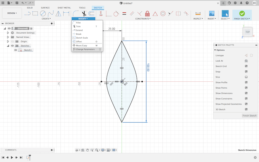
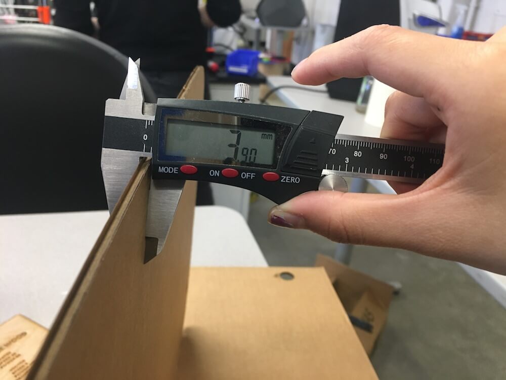
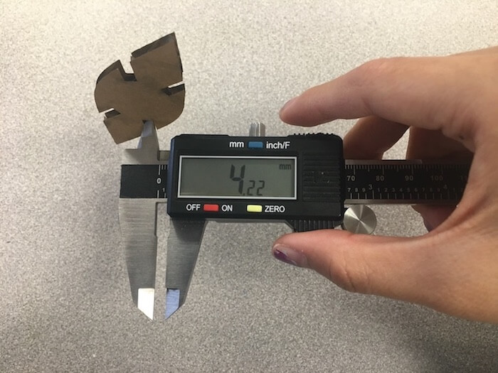
With digital calipers, I measured the exact thickness of the cardboard I planned to use.
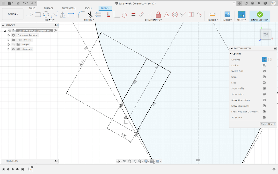
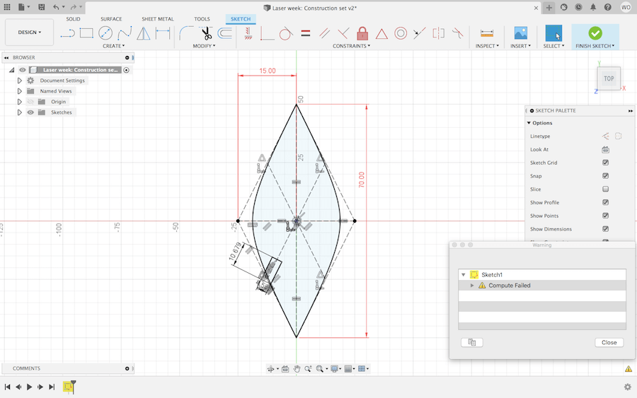
With that information, I created 3.9 mm notches in my sketch. Once again, I added constraints and sketched dimensions, which created new parameters. However, when I tried adjusting the overall length of the shape there was a computational error. I think this was because the rectangular notch was locked in place by its constraints, which prevented the outer shape from changing dimensions. To fix this, I backtracked to correct the total length and width before I made the joints. Then, I used the Mirror feature to duplicate the notch in symmetrical places.
Fusion to Epilog Laser
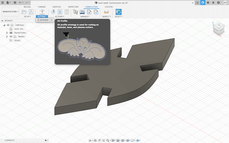
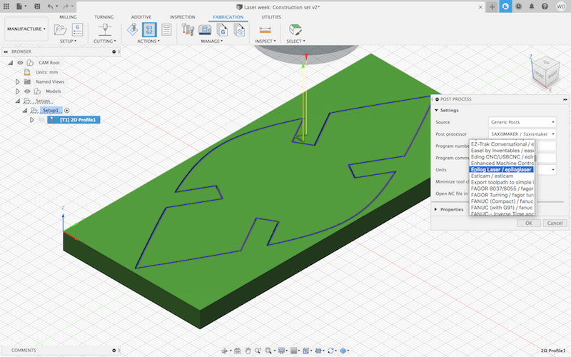
Once I had my sketch, I went into the Manufacturing Workspace. This was the first time I used this area of Fusion. Professor Goodman provided some step-by-step instructions on how to prepare a file for cutting (either laser or CNC) in Fusion 360.
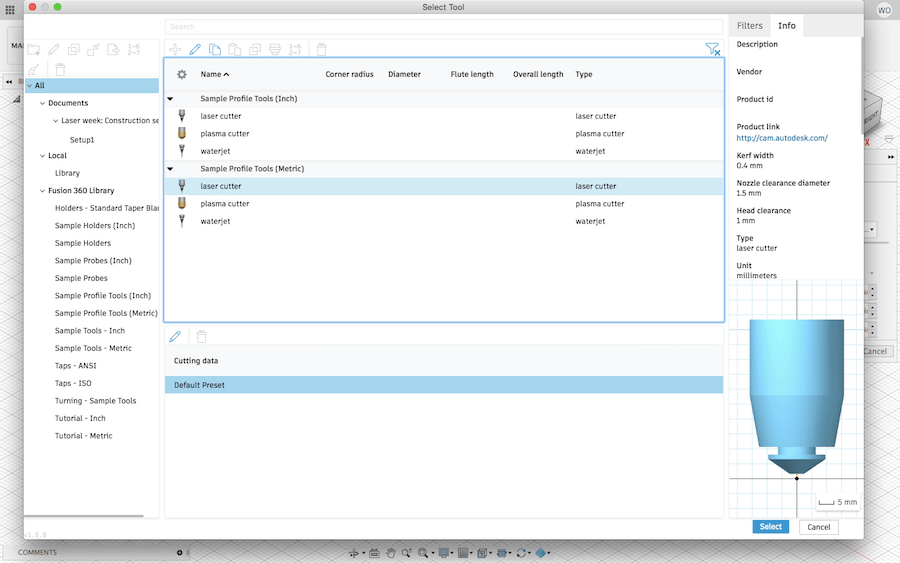
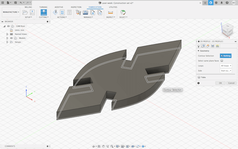
Since I had a flat object, I used the 2D Profile option, and changed the tool to laser cutter (metric). I made sure to select my objects outline, under the Geometry tab. Then under Passes, I was able to choose if I wanted the laser to cut exactly on the outline, or to the left or right. For the first test cut, I set this to cut on the center because I wanted to see how the joints would work if I didn't account for the kerf.
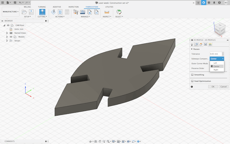
Press-fit joints work by making the joint gap almost the same width on the inside as the material is on the outside. However, I found that my test cuts were definitely too loose. This is because a small amount of material gets removed along the path of the laser --the kerf-- and since I set the laser to cut directly on the contour in Fusion, that made the joint gaps slightly larger than they needed to be.
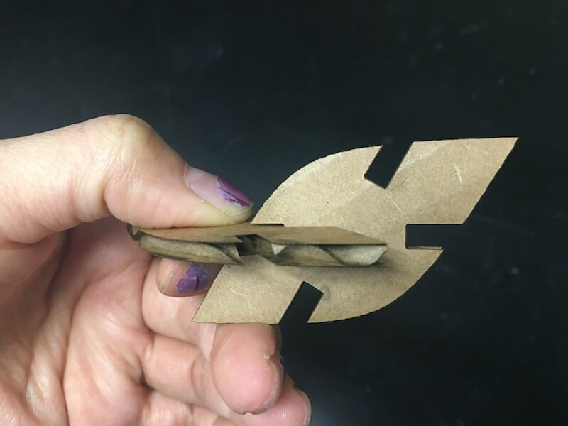
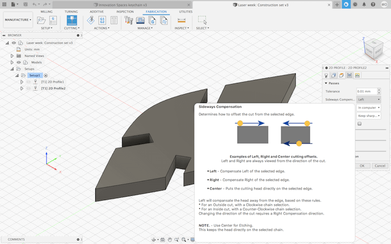
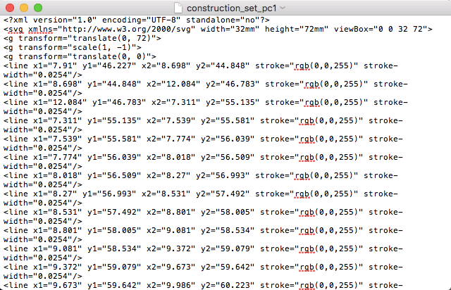
Back in Fusion, I changed the Sideways Compensation to Left. This is taking into account Fusion's default kerf settings for a laser cutter. I figured the default kerf might not be the same for an Epilog Laser, but after making the cuts, I found that the joints fitted pretty well. To save my cutting file, I went to 'Post Process' and chose the Epilog Laser as my machine. The first time I tried opening up my newly saved file, it appeared as a text document. I realized this was because I forgot to add ".svg" to the filename when saving it after the 'Post Process'.
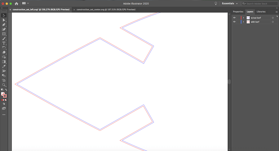
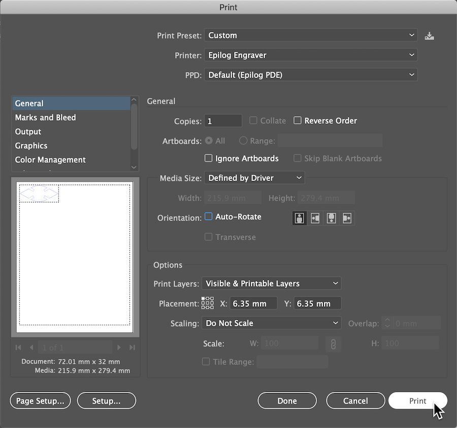
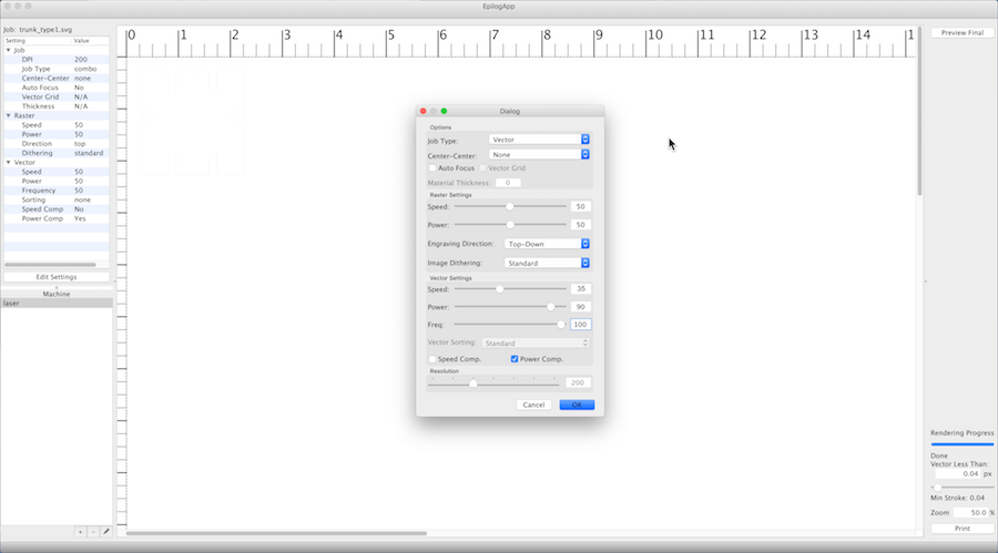
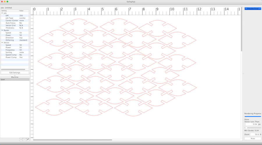
When I opened up both of my files (with and w/out kerf) in Illustrator, I could see the difference. The red line takes the kerf into account, so the joints are slightly narrower. Before I printed the red outline to Epilog Engraver, I made sure that the line weight was .01 mm, for vector cutting. In EpilogApp, I changed the laser settings to speed 35, power 90, and frequency 100, and printed it.
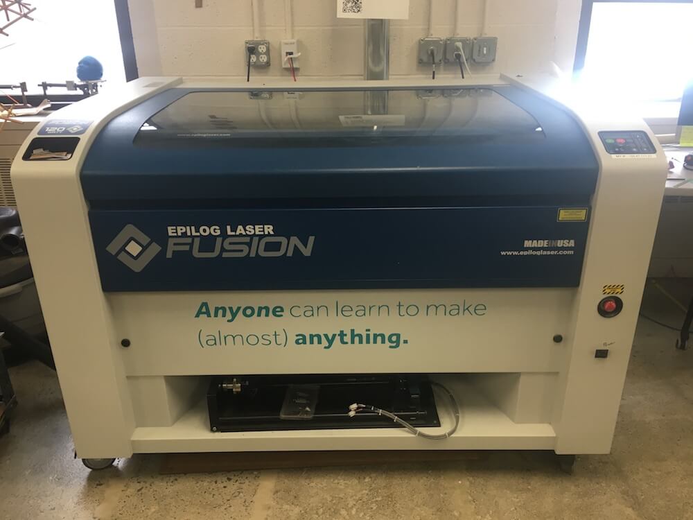
Epilog Laser
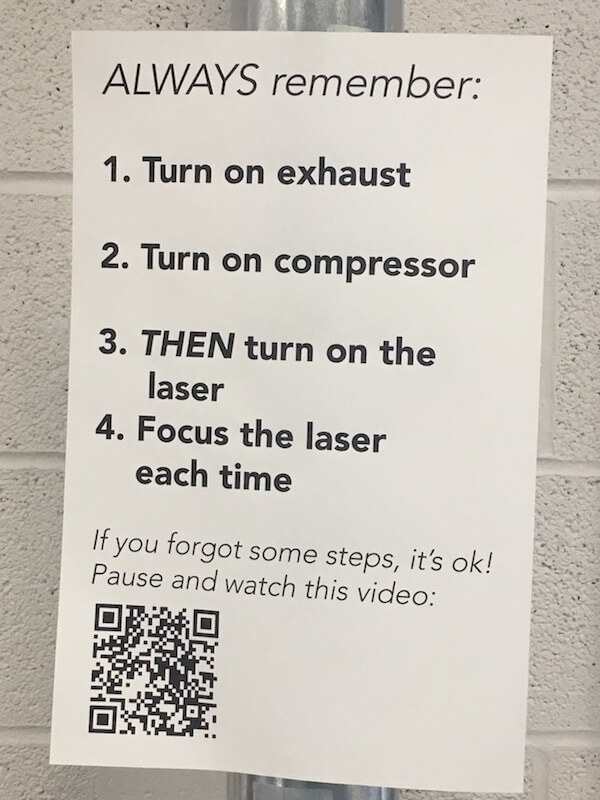
To operate the laser cutter, I go through these steps.
- Turn on the exhaust and compressor.
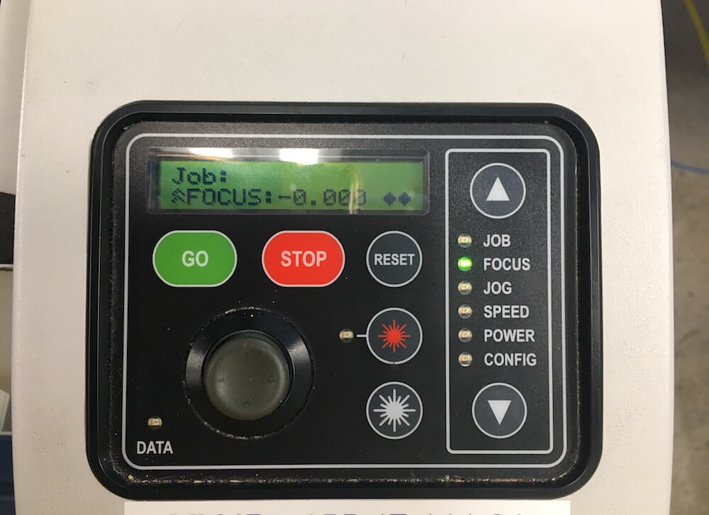
- Raise the laser bed by going to FOCUS and moving the joystick. Use the metal triangle tool to distance the laser correctly. Press in on the joystick to set the focus in place.
- Move the laser head by going to JOG. Place the head in the upper left corner of the cutting material. Press in to set the origin in place.
- Start the cut by going to JOB and pressing GO.
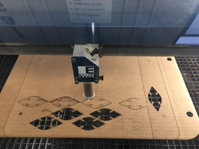
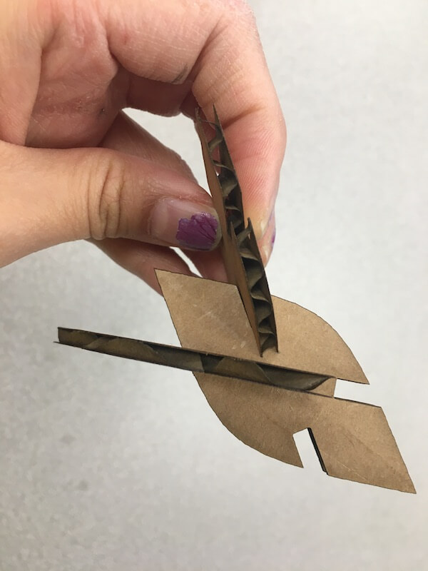
Once I knew I could make joints that worked, I designed a couple other modular units for my construction kit. These photos show how I made the other parametric designs.
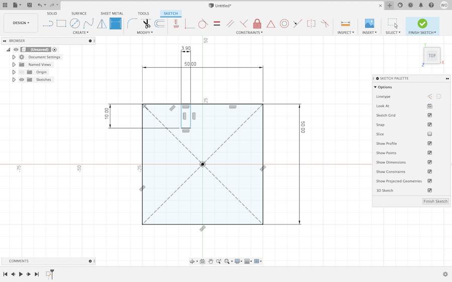
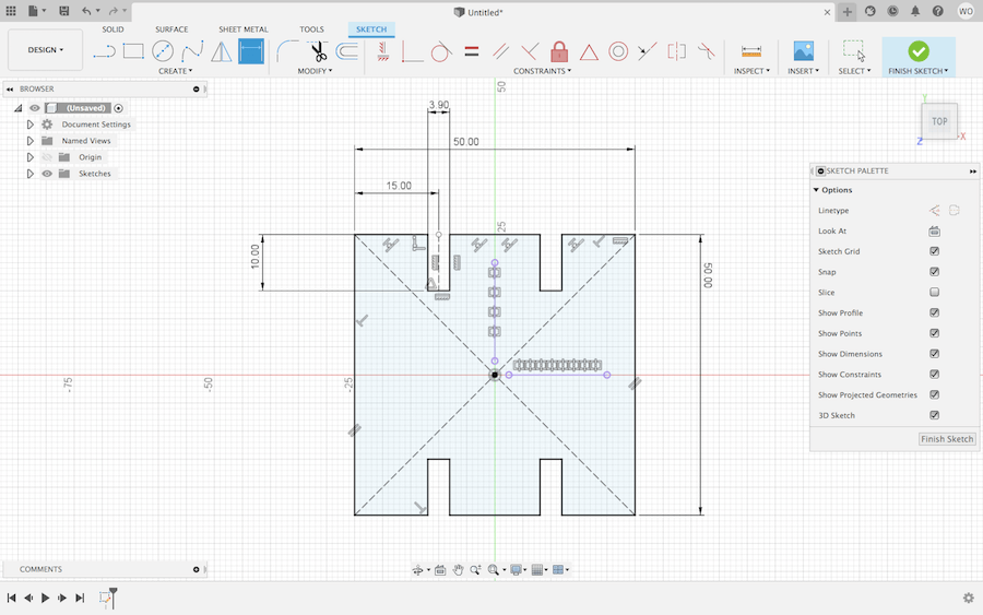
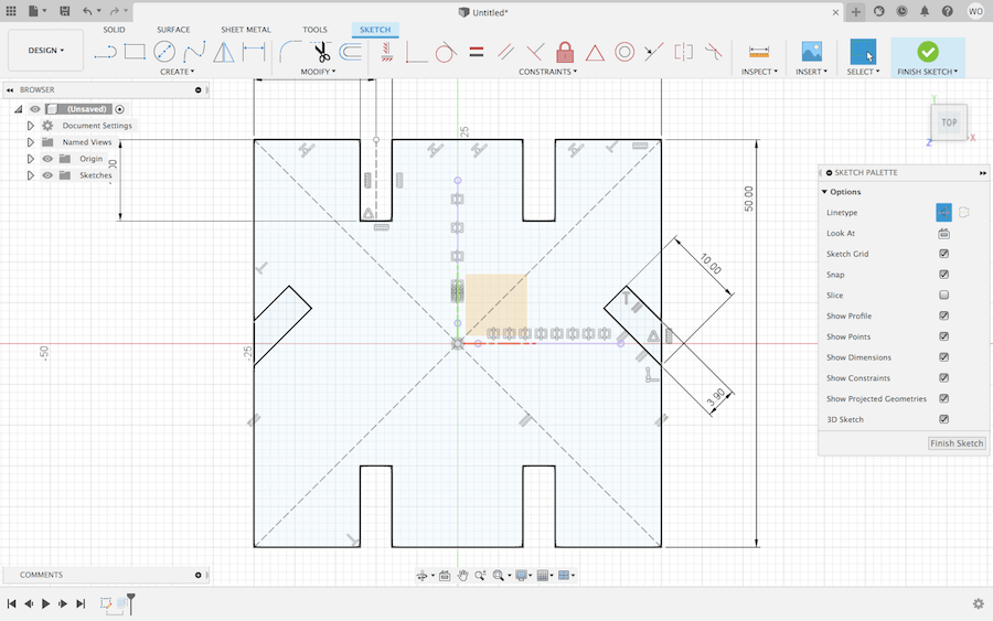
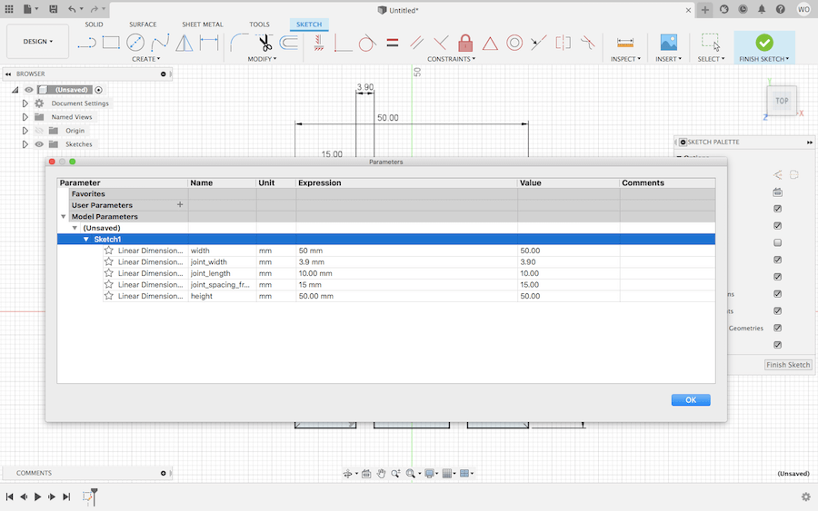
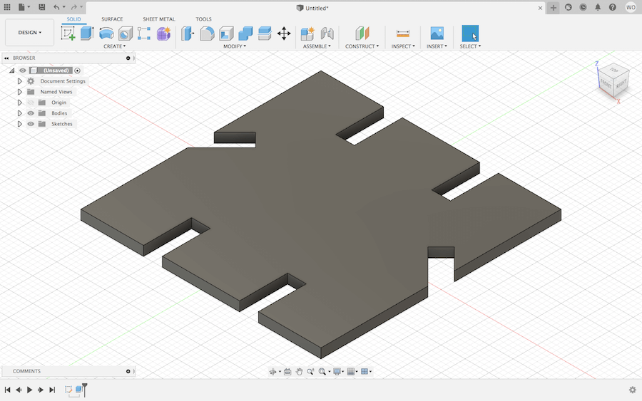
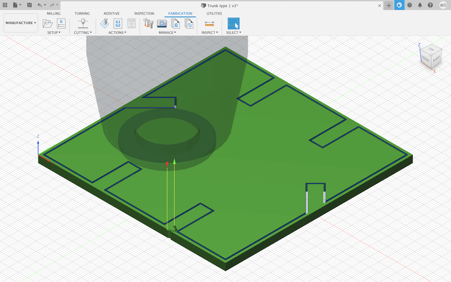
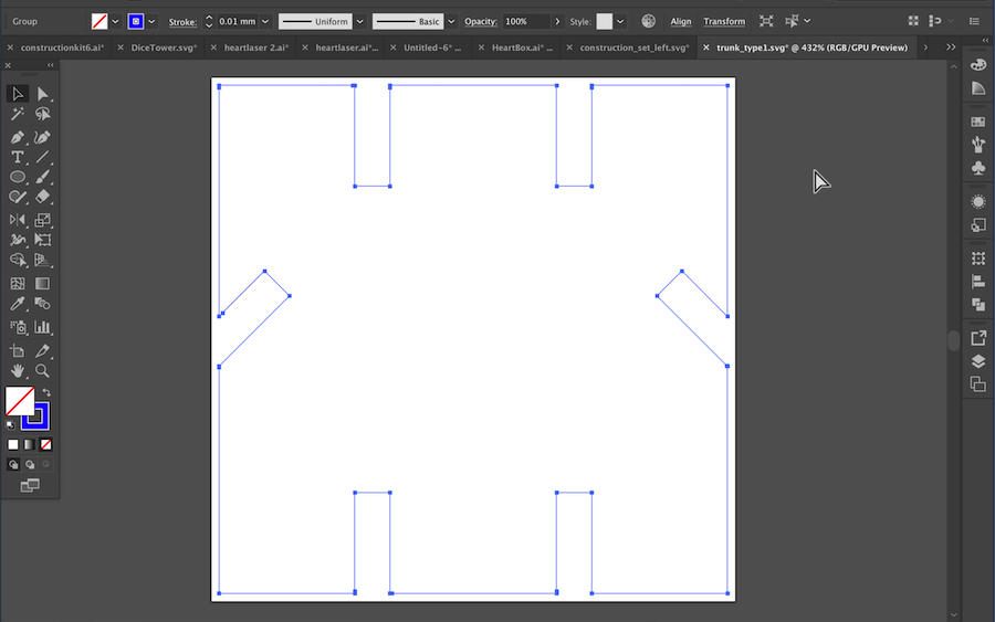
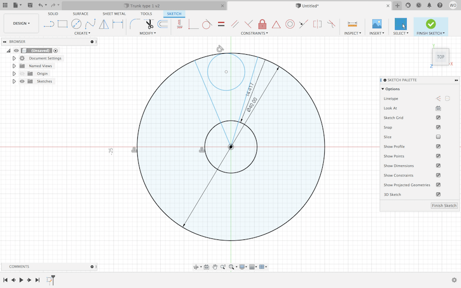
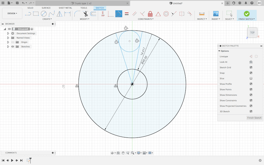
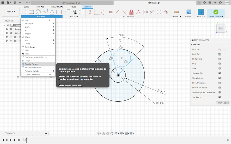
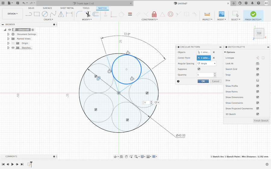
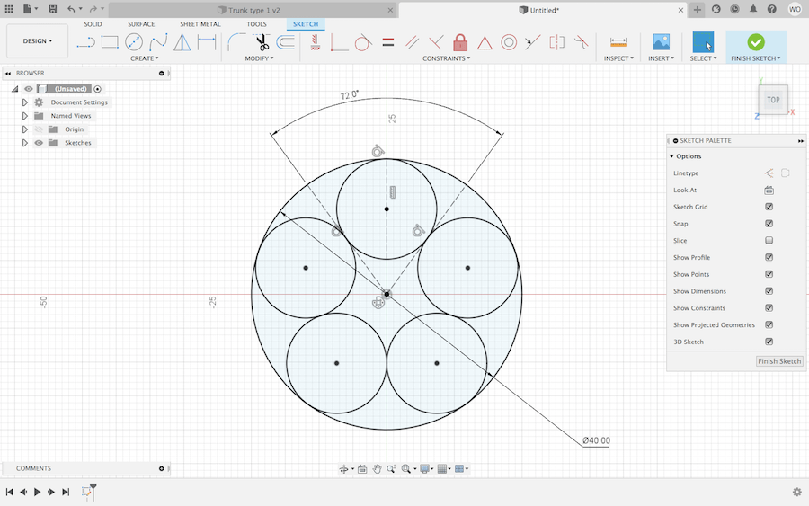
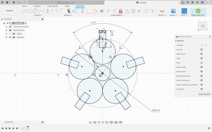
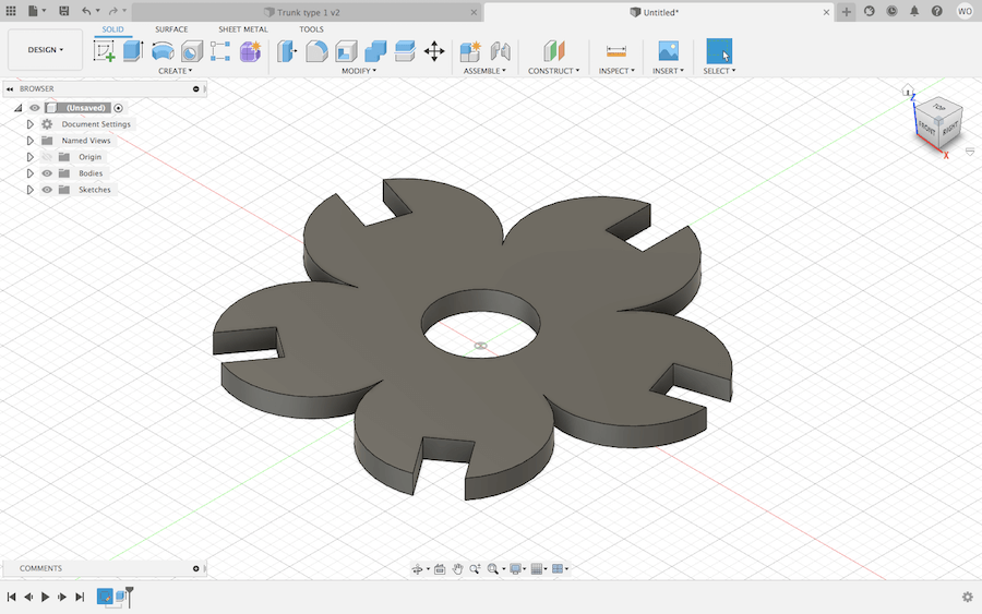
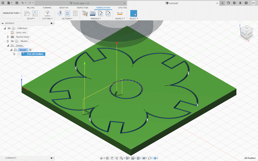
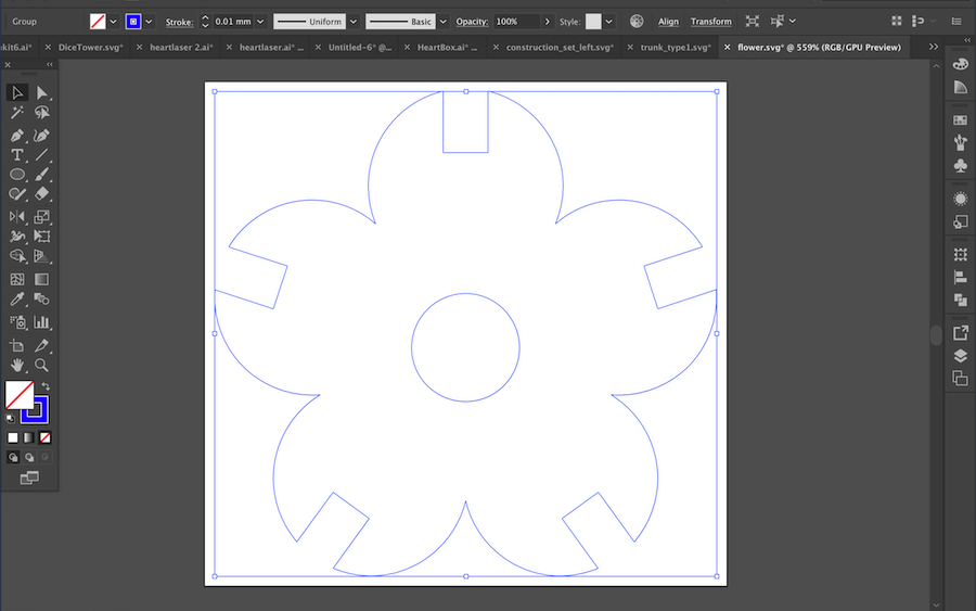
I repeated the same process to get my design from Fusion 369 to Illustrator, and then to the Epilog machine. After cutting some of these items multiple times, I found that I could increase the speed to 40 or 50. I also copied and pasted my designs in Illustrator to cut multiple objects at once.
Finally, I got to assemble the construction kit! Or in this case the tree.
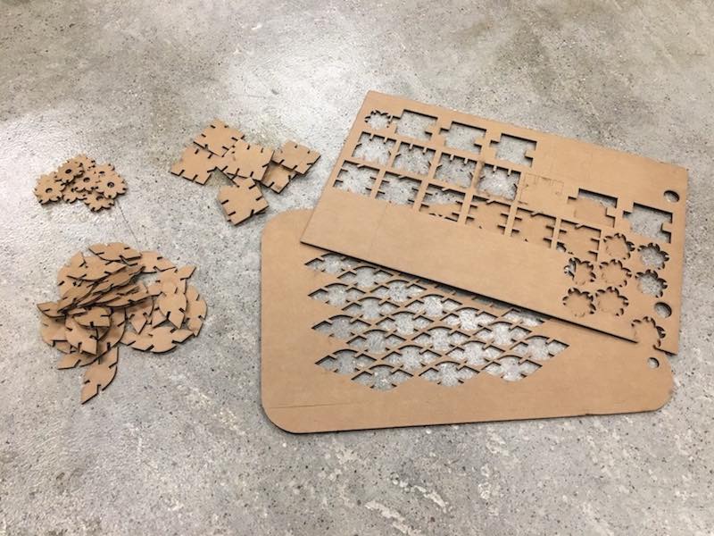
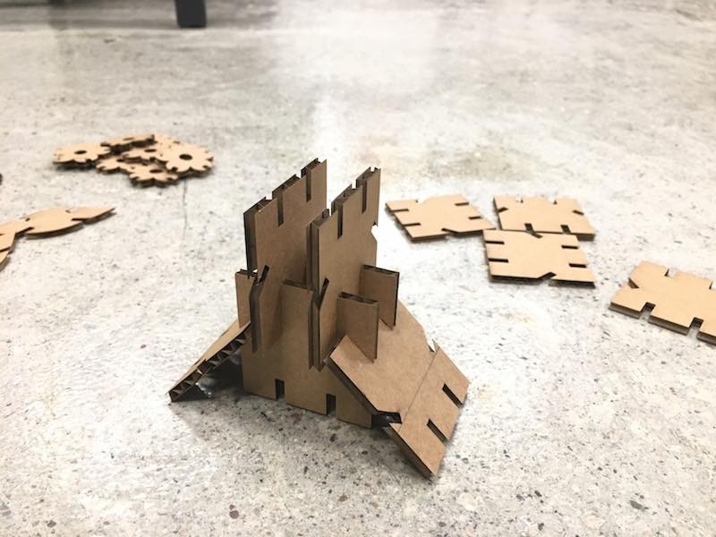
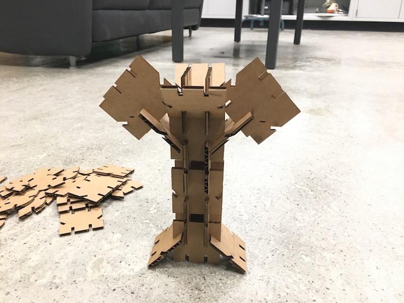
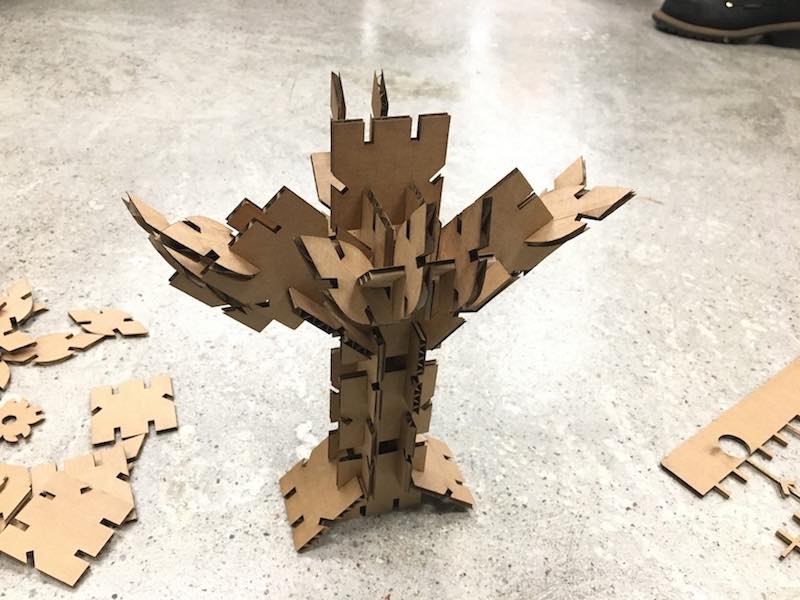
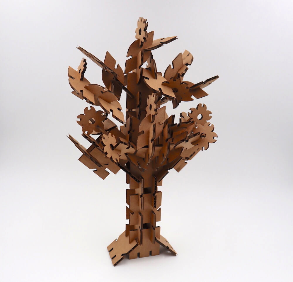
During Computer-controlled cutting, I learned how to use Fusion's Manufacturing Workspace, a skill that will come in handy for future CNC projects. I also have a better understanding of kerf, and how to account for it when designing parts. Overall, I'm very happy with the construction kit I made. Each of the three modules are parametrically designed, and their joints fit together well. I also think it's a really cool art piece. It can definitely be assembled in multiple ways. I didn't sketch out anything beforehand, so assembling it was like a puzzle. I had fun putting this together to get it to balance and look like a tree!
Resources
Design Files
Updated: February 16, 2021
