12. Mechanical design, machine design
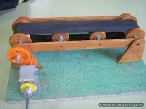
The idea is to design and implement a conveyor belt. To do this, a model of a conveyor belt was searched on the internet and we found one. It was a very simple and necessary model for what we wanted to do. We show it in the following image:
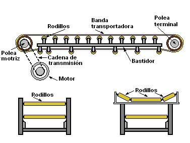
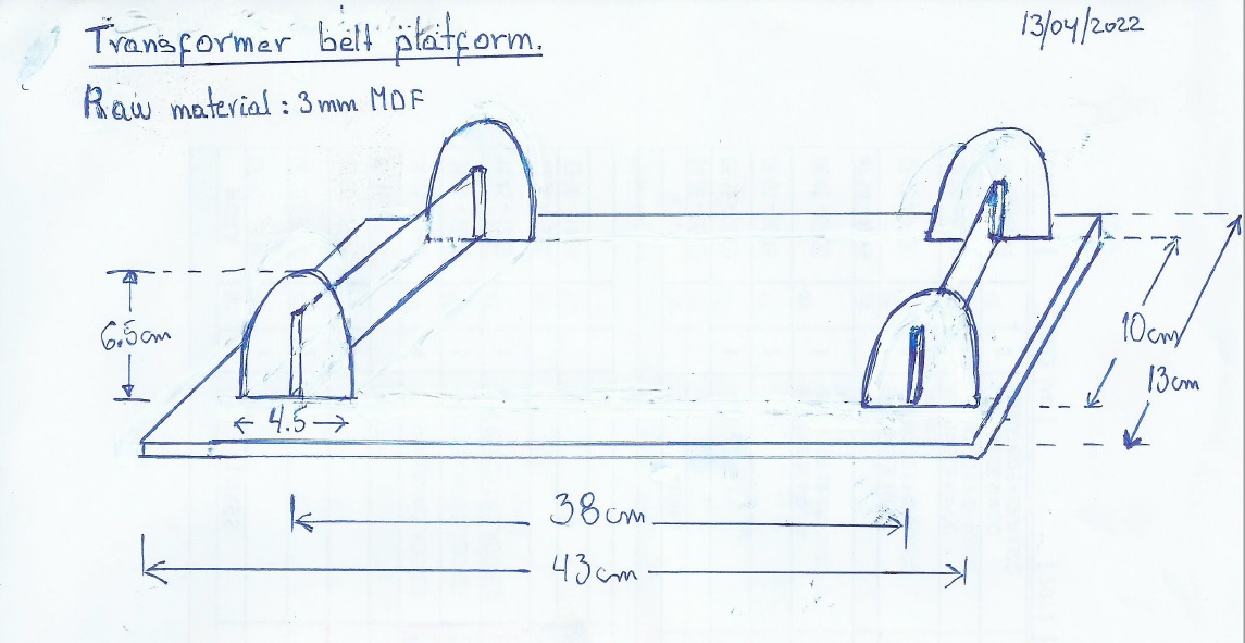
My partner Alberto added an image with more detail and made a freehand sketch of it, specifying the corresponding dimensions.
Sketch:
Having a clearer idea of what was intended to be done, in coordination with my partner, we assigned ourselves tasks to manufacture the conveyor belt: Who would be in charge of the CAD design and the respective cut in the laser cutter would be me; Guadalupe. Alberto would be in charge of the assembly and its operation.
Individual assignments
My contribution in the development of this work has been the design and cutting of the conveyor belt.
Design
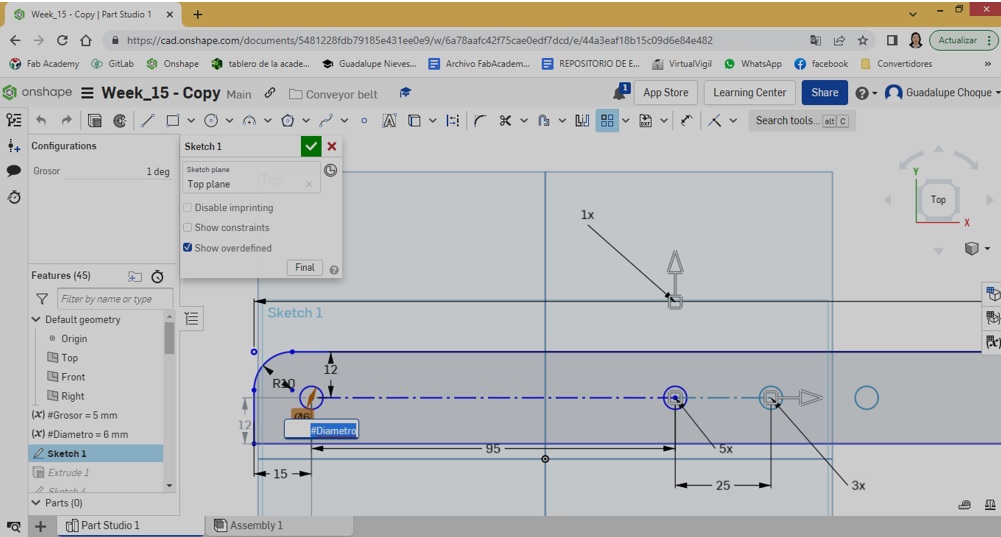
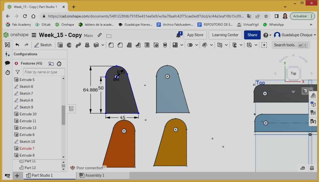
Taking the image of the belt shown at the top as a model, the design began with the layout of one of the sides of the 41 cm conveyor belt. x 2.5cm. Once its corners were rounded, a first eyelet was inserted (where the screw would go through) to which 6mm was assigned. diameter. This value was considered taking as a reference the diameter of the screw that would be used in the assembly of the belt.
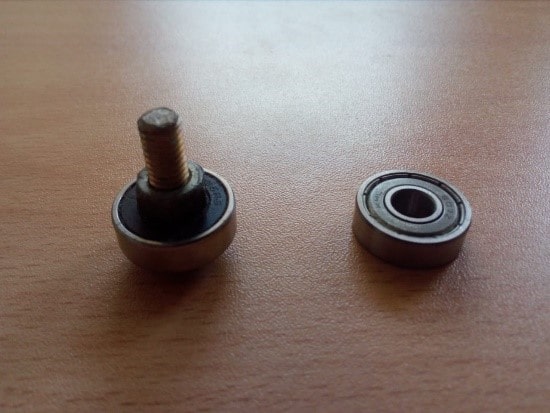
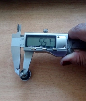
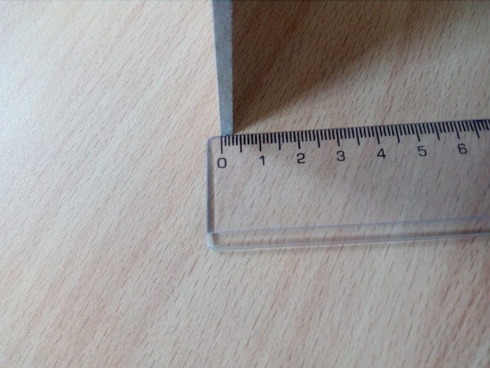
With the help of a vernier, the diameter of the screw was measured; 5.57mm.
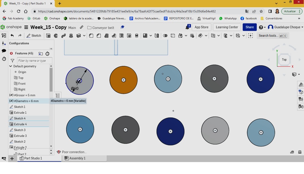
Because the buttonhole is reusable, the variable #Diameter was created, with the value of 6mm. thus applying parametric design to all the eyelets of the components of the conveyor belt; such as sides, bases and circles.
Then the Linear Pattern resource was applied, thus creating four more circles, thus making a total of 5 circles (thinking of a better support, unlike the model that has 4) spaced 9.5cm apart.
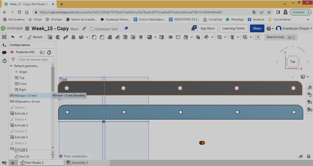
Once finished with the side design, extrusion is applied with a depth equal to 5mm. This value was also assigned to the #Thickness variable and finally a copy is made, thus obtaining a second side.
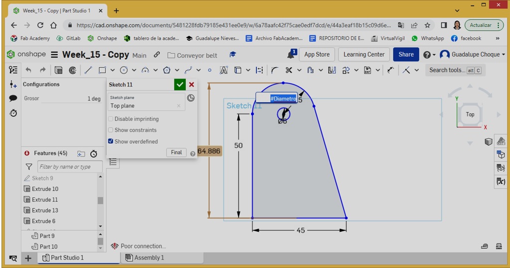
Then we continued with the design of one of the supports.
From there, 3 more copies are made. In total there are 4.
Lastly, the wheels were designed. From one, 9 copies were made.
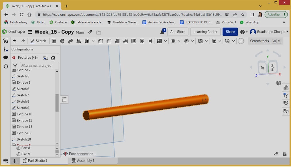
For simulation purposes, an object was designed to play the role of the screw.
To see the final result we proceeded to the assembly.
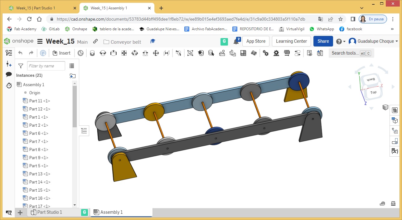
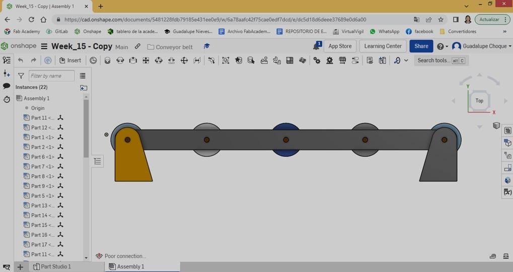
Sample of the completed design.
Court
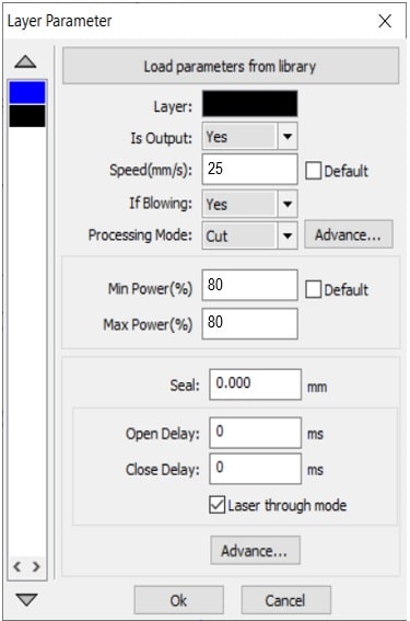
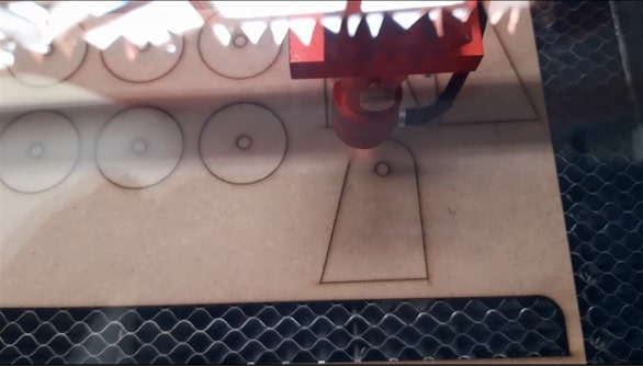
Having loaded the CNCLaser software, I proceeded to import the DXF file, previously exported from Onshape.
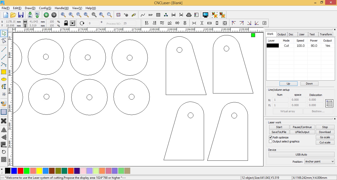
I do the cutting configuration taking into account that the material to be used for its cut is 3mm MDF. Therefore, it corresponds to work with a speed of 25 mm/s and a power of 80%.
Then proceed to download the file.
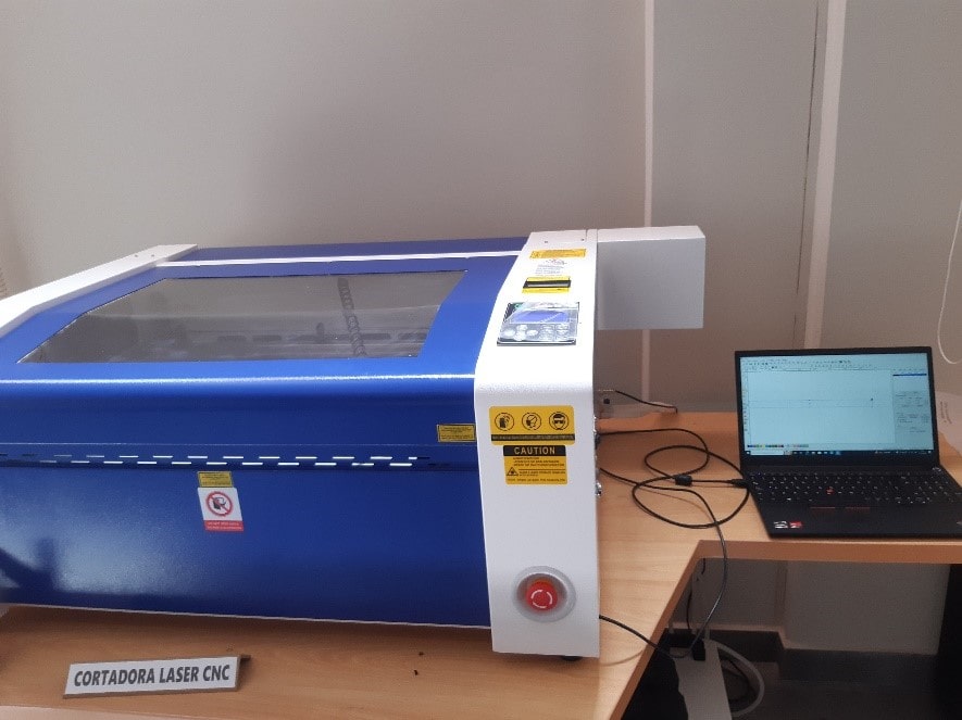
Once the file is downloaded in the laser cutter, I prepare the MDF to use.
I place it on the slicer tray and order the cut (RUN) through the slicer Control Panel.
Cutting process in the video.
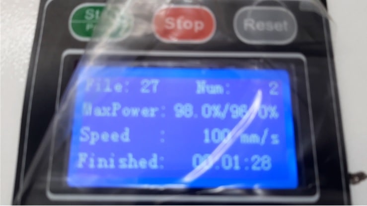
The cut lasted 1 min. 28 sec. as can be seen in the following photograph.
As the cut has not been total, a second pass is carried out. Therefore, we proceed to order the cut again.
Once the second pass is finished, I order the cut pieces.
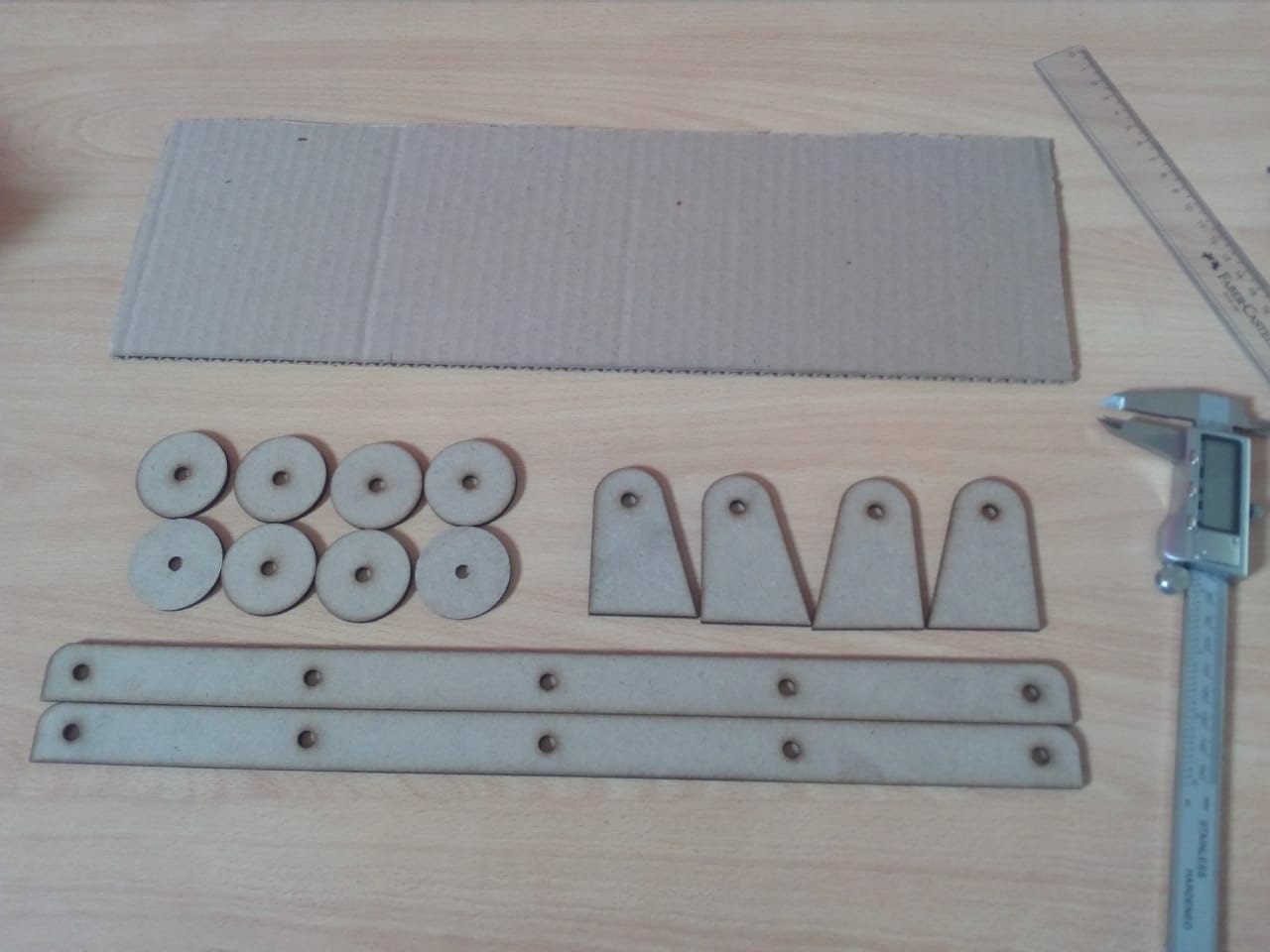
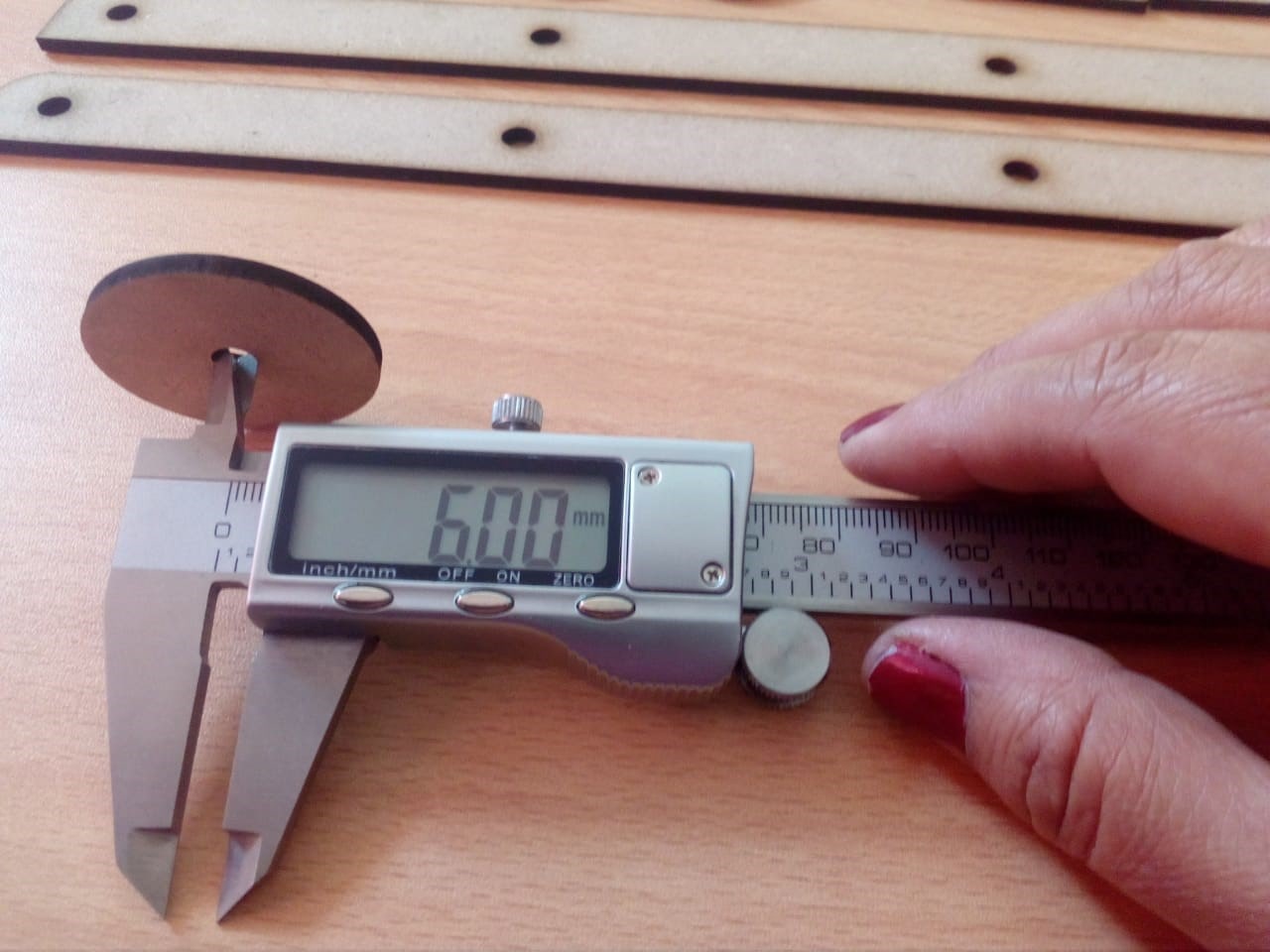
I take one of the pieces to corroborate the measurement of the diameter with the help of a vernier.
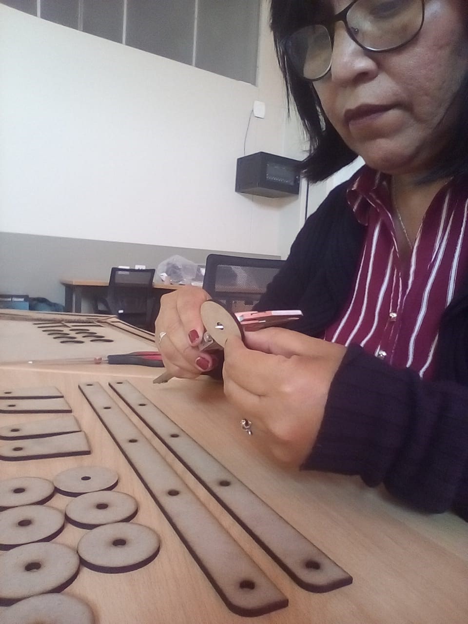
And indeed, as indicated in the drawing, it is 6mm.
Now testing the screw and the cut piece.
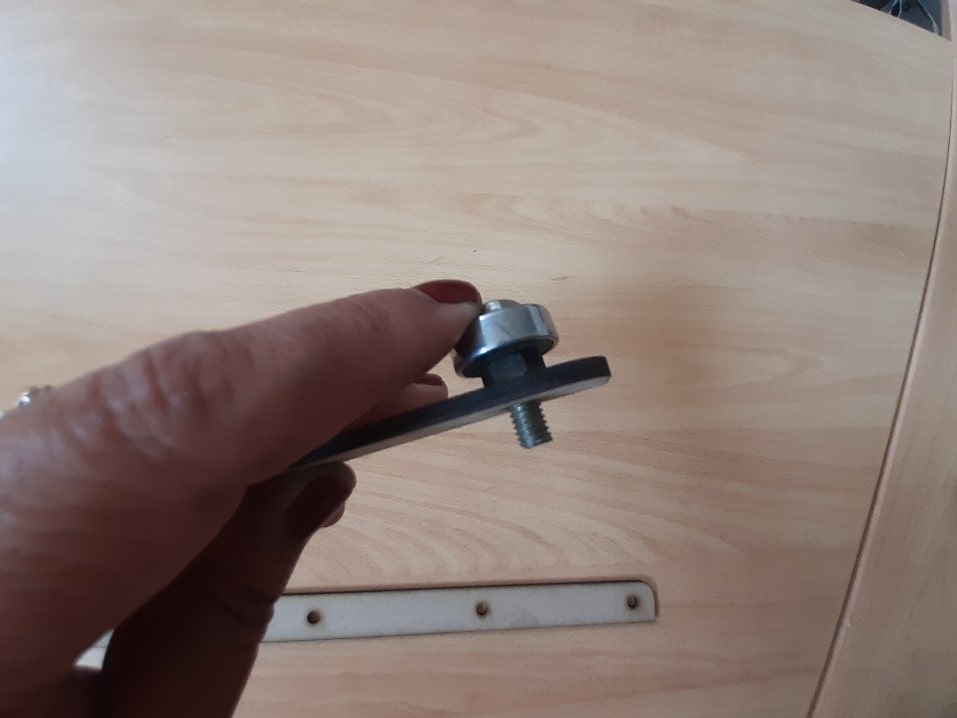
Fits perfectly!!!
Leaving it ready for assembly.
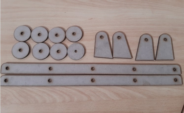
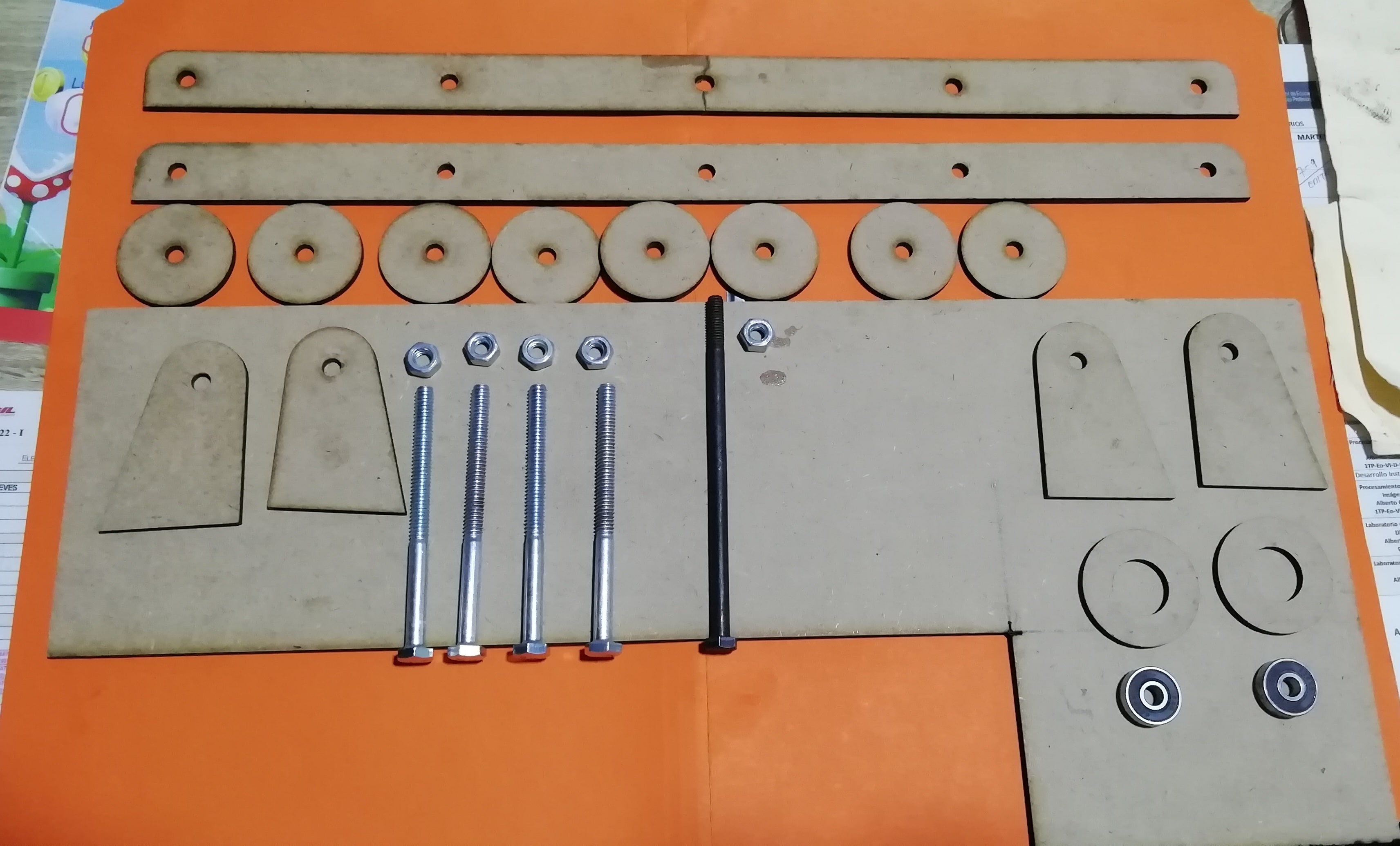
Leaving the pieces cut and ready for my partner to start the assembly and work on its operation.
Working in group
Picking up the cut pieces, my partner continues with the group work.
Armed
Completing components for the assembly
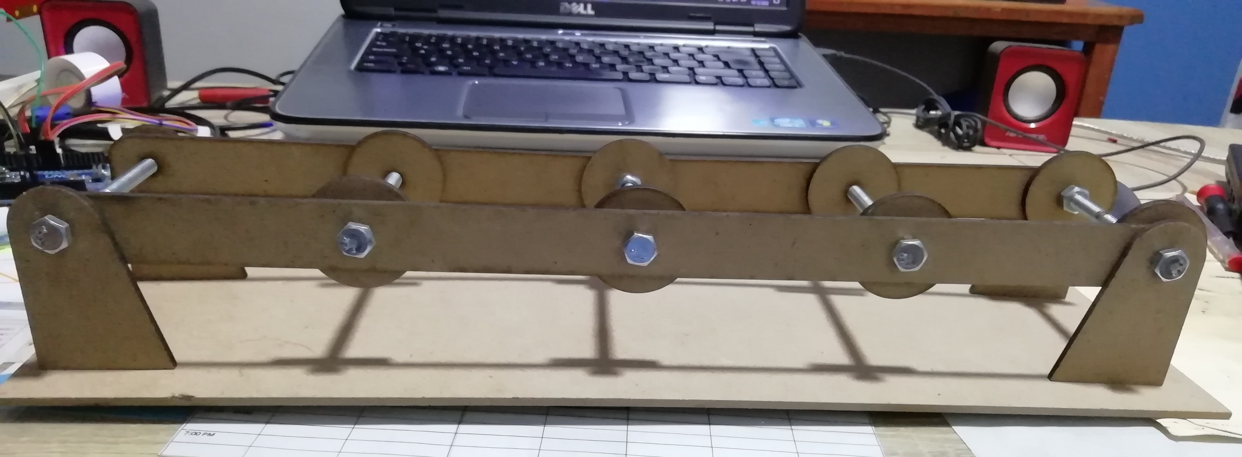
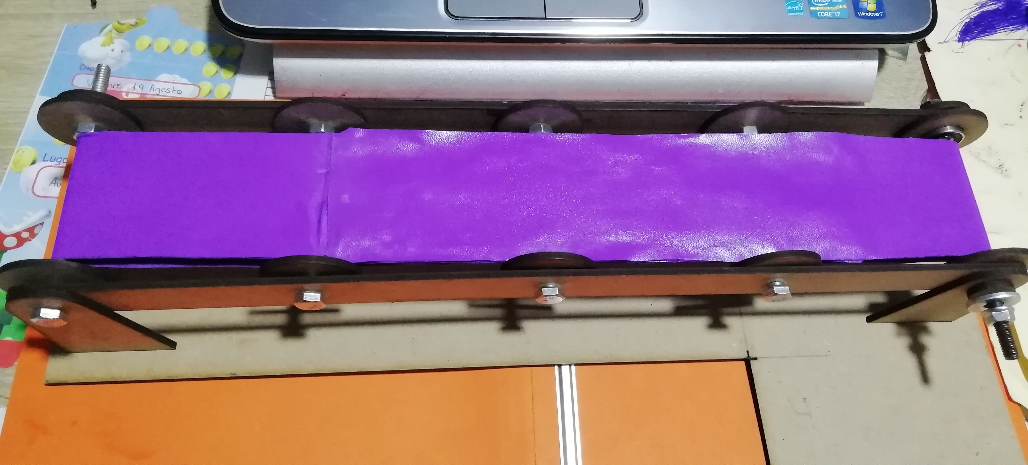
Assembling this is how it looks like:
For the rollers we use 1/4 inch PVC pipe.
For the motor shaft roller we line it with sandpaper so that it can pull the belt.
For the conveyor belt we use corrospum, the rough element is placed inside, the smooth part outside.
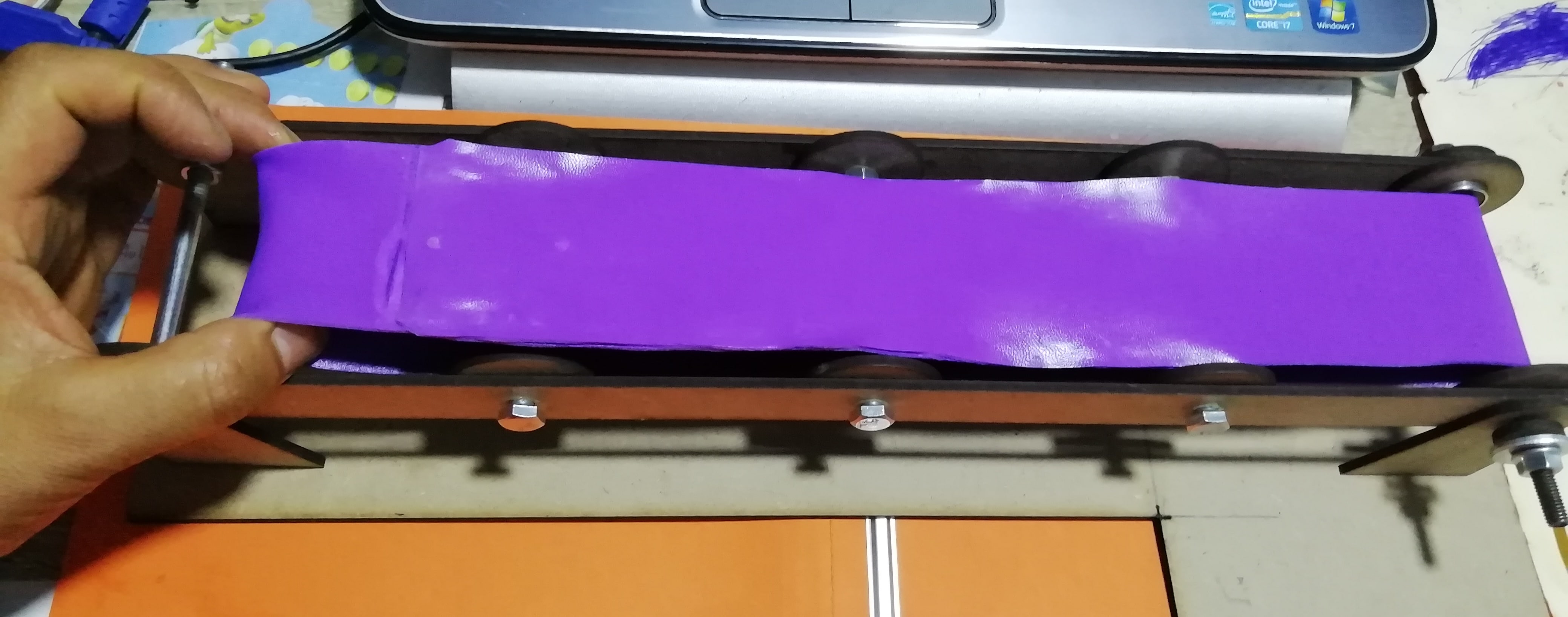
Then, this is how the transprtator band looks like to me.
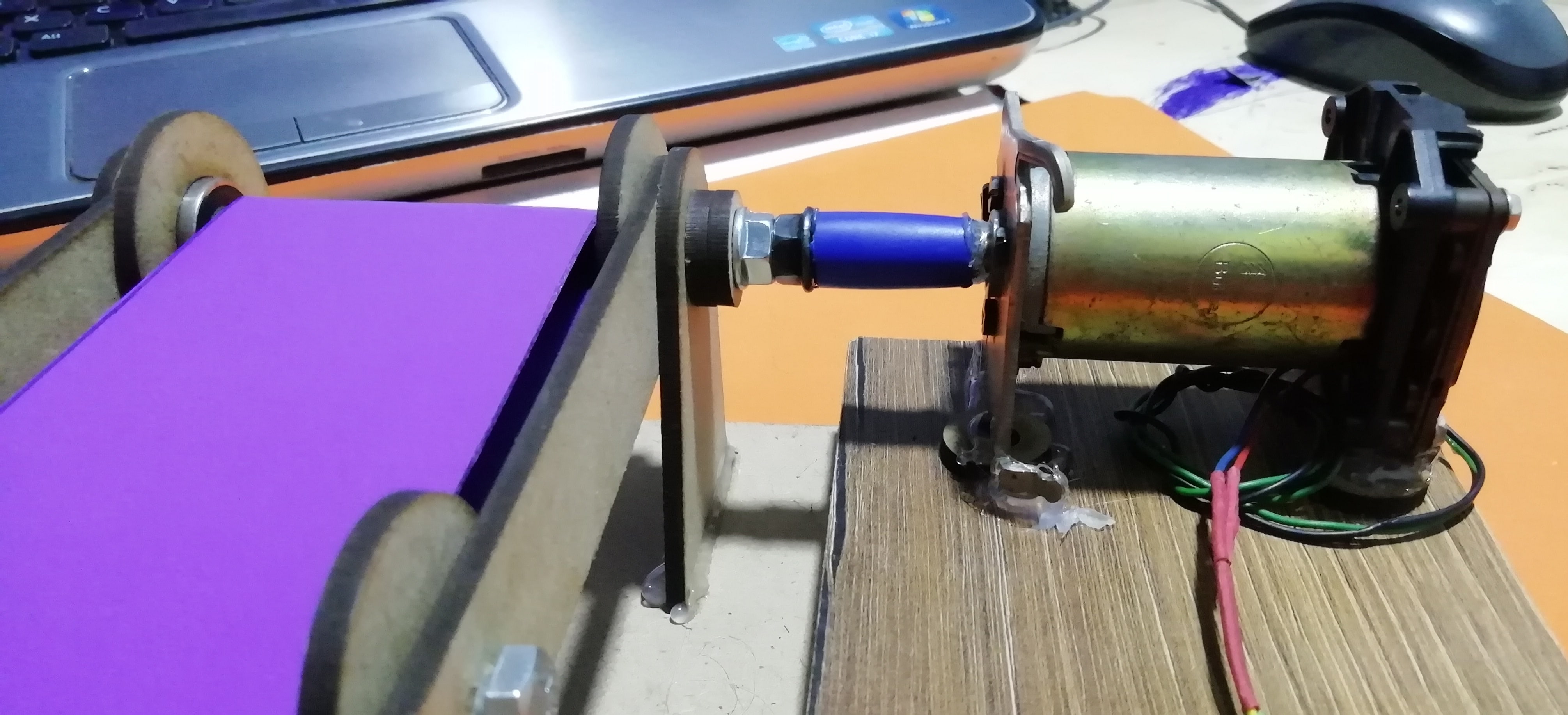
To couple the drive pulley and the DC motor, a timing belt should have been used first, but since it was not available, corrospum was cut and did not work.
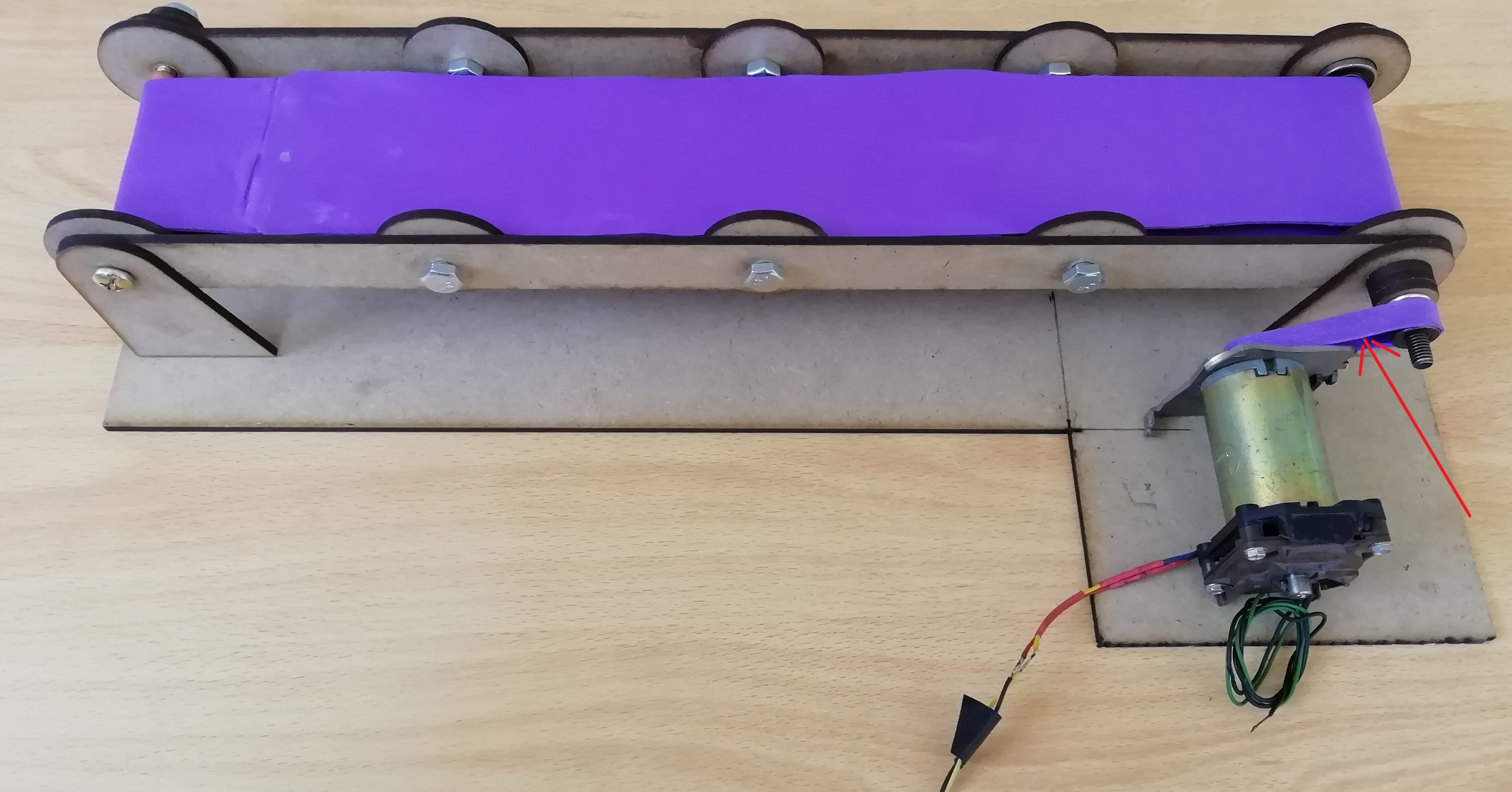
Directly coupled to the drive roller shaft with the motor.
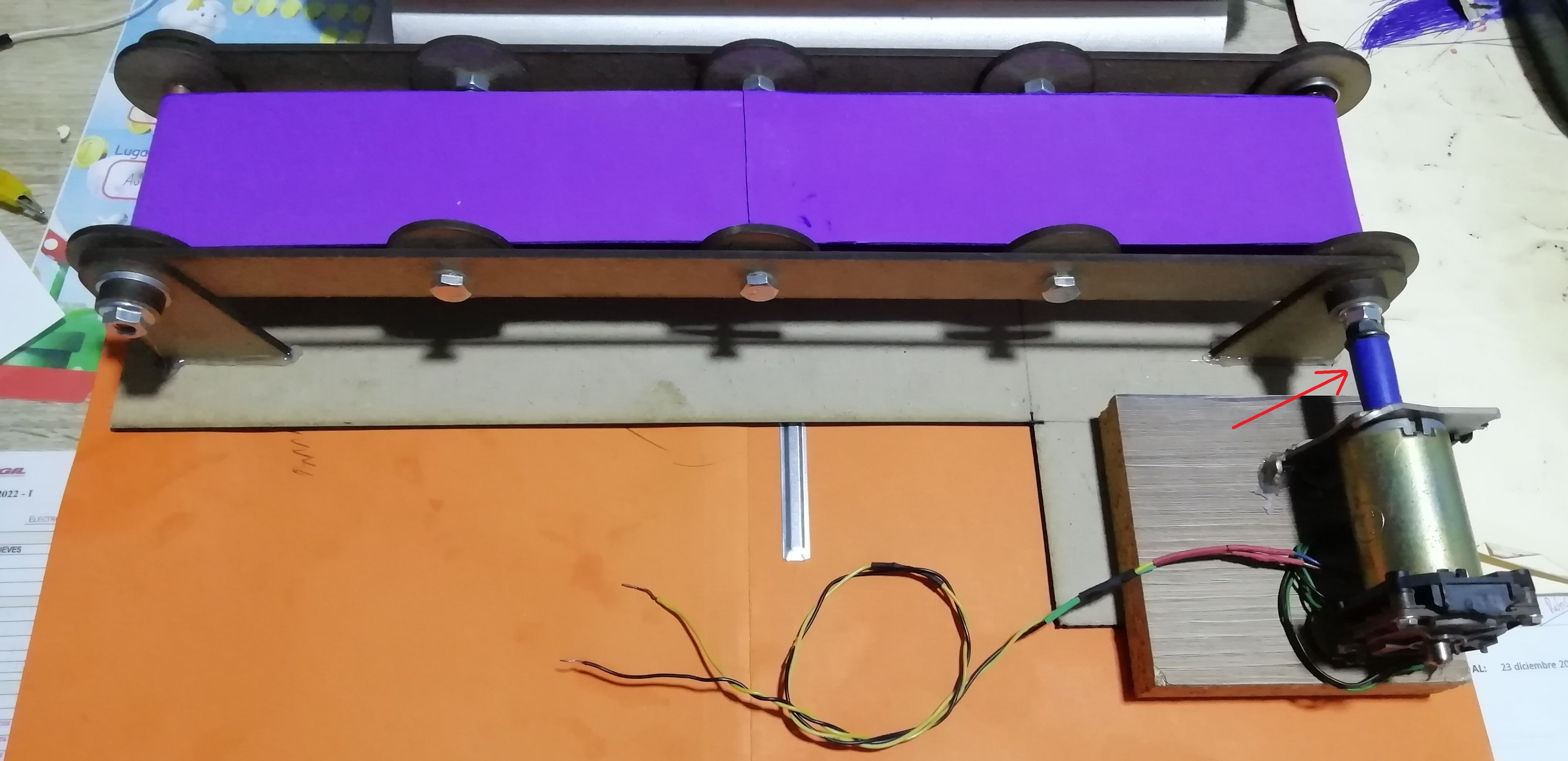
This is a side view of what it looks like:
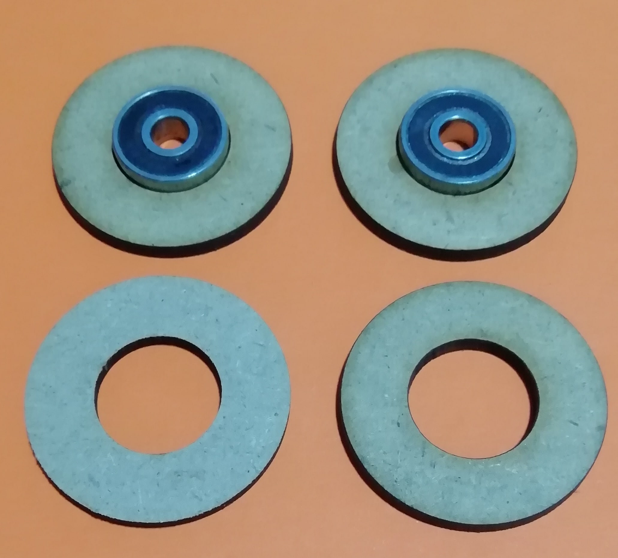
This is the process of laser cutting the circles of the drive shaft bearings:
This is a video of the placement of the bearings in the circle:
Conveyor Belt Manufacturing Testing.
Natives files
| Ord | Description | Files |
|---|---|---|
| 1 | Support design | Support.dxf |
| 2 | Side design | Side.dxf |
| 3 | Circle design | Circle.dxf |
| 4 | Wheel design | Rueda.rld |
| 5 | Wheel design 2 | Rueda2.rld |