8. Computer controlled machining
Working in group
Characterization of the printing rules of your 3D printer(s)
We will use 9mm MDF as raw material.
To test the progress and trajectories of the cutting machine, we will design the test piece in 3D CAD, Onshape.
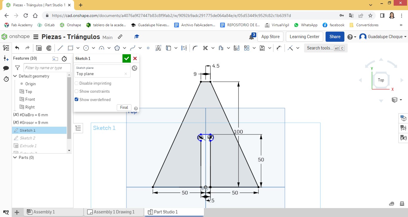
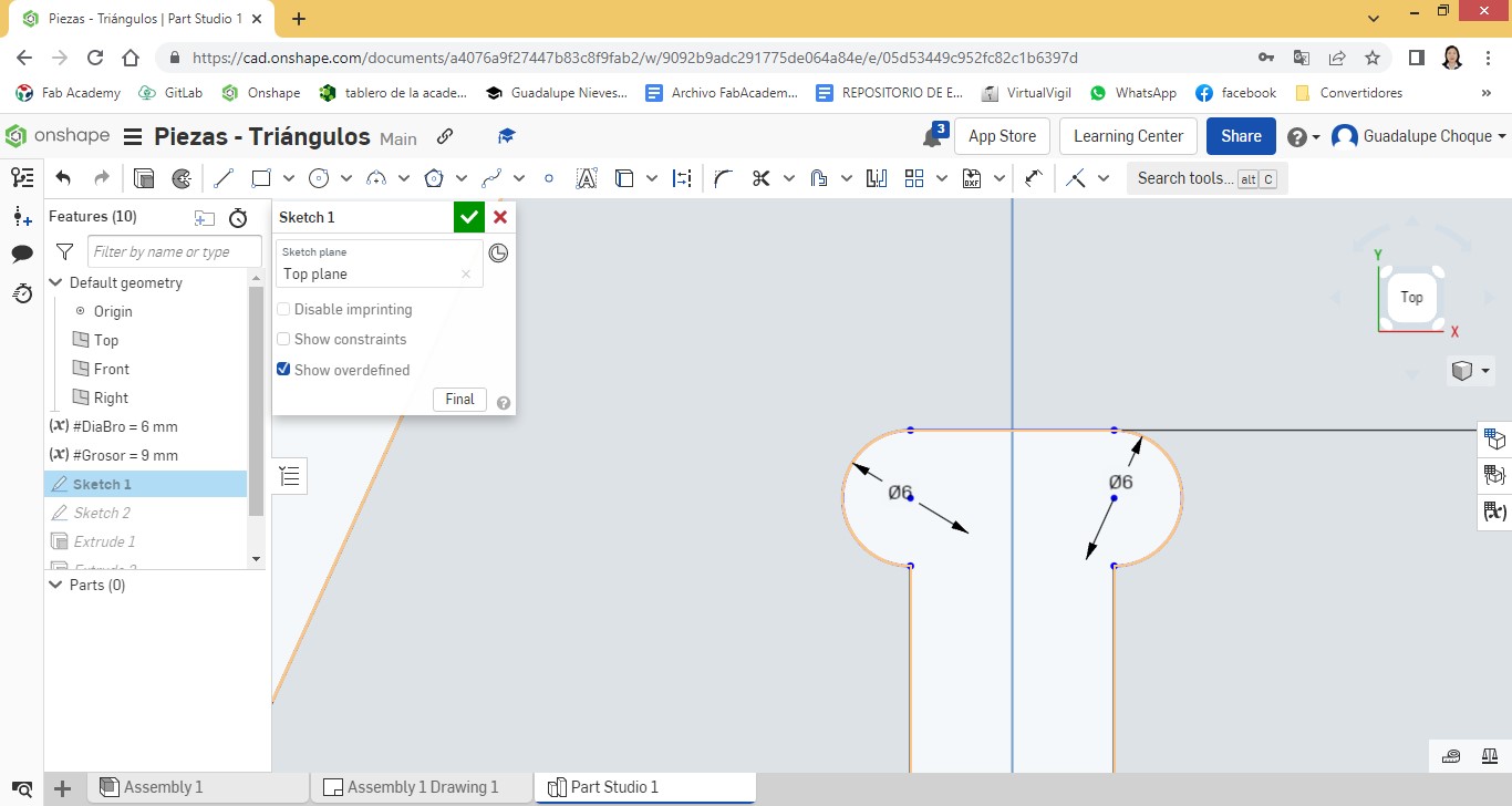
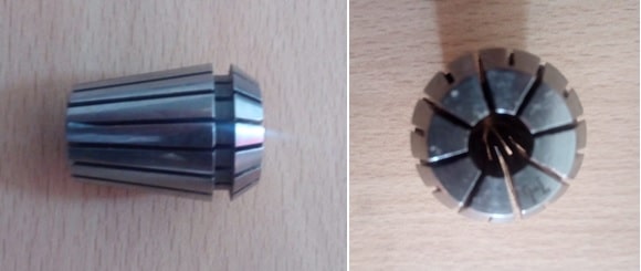
We will use the tip of the 6 mm drill bit.
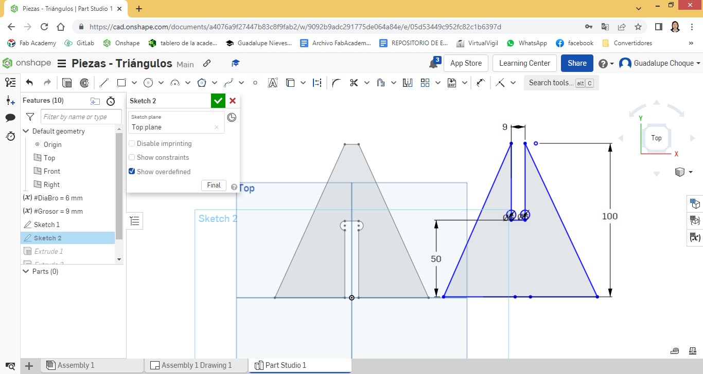
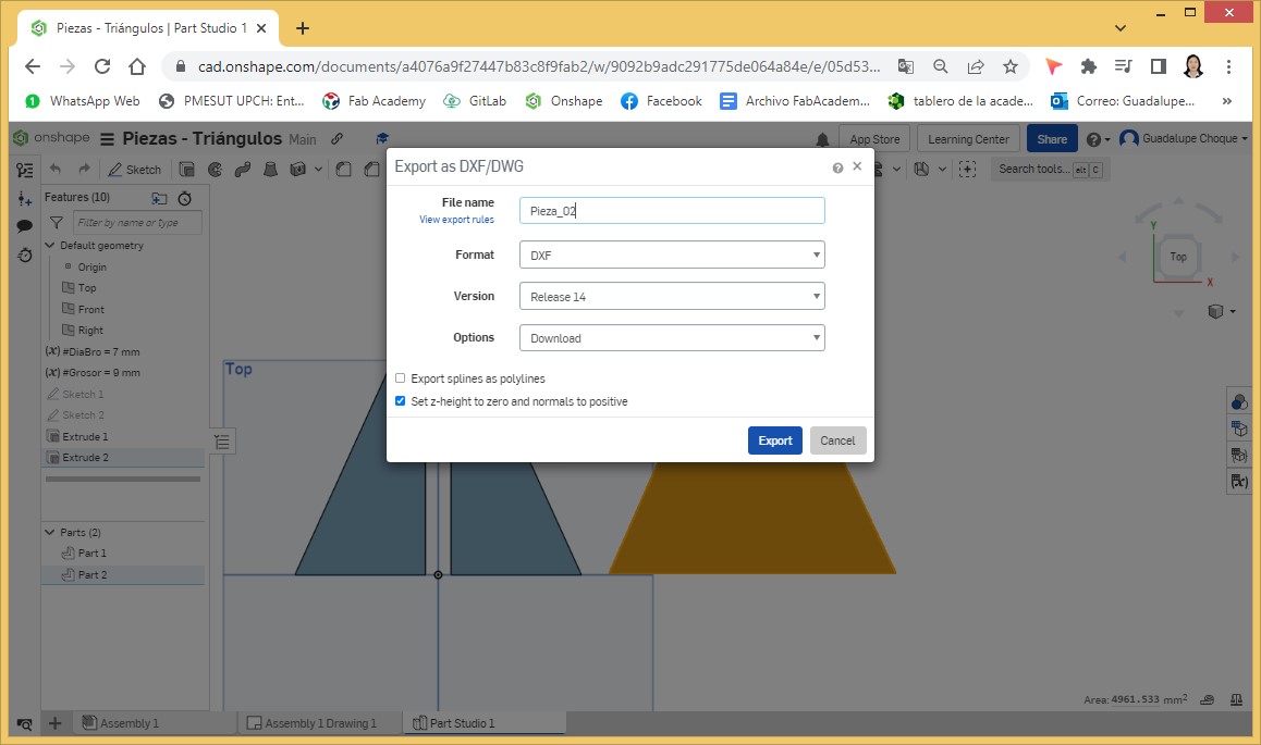
Then, we proceed with the design of the second piece.
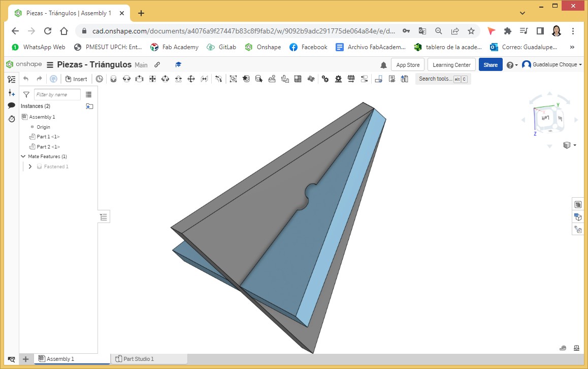
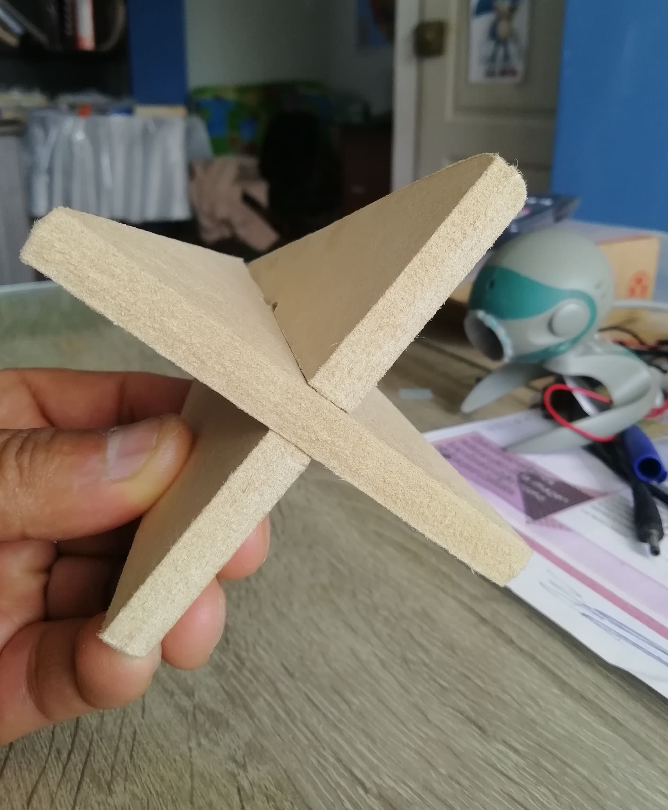
We show an isometric view of the assembled parts.
A 45 degree view.
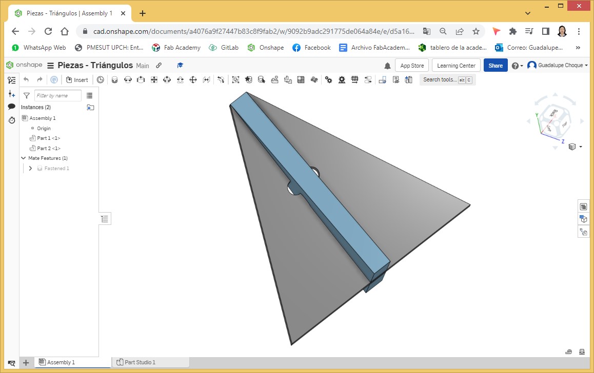
A view at 135 degrees.
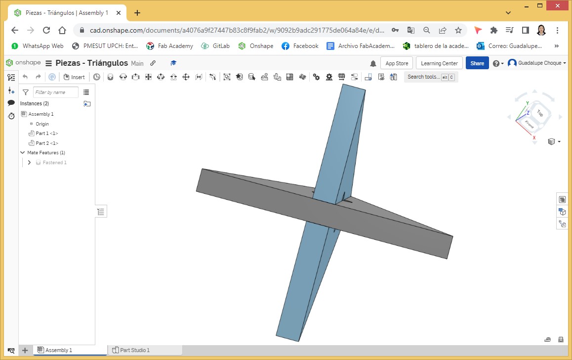
A view from the bottom.
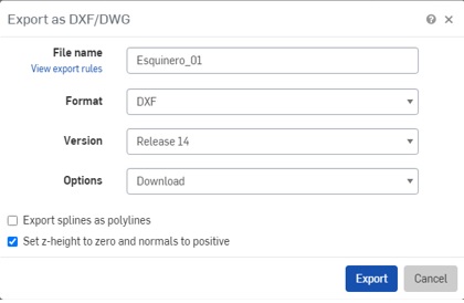
We prepare the pieces for cutting in DWG file.
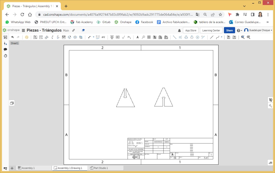
Downloads of parts 1 and 2 in DXF format.
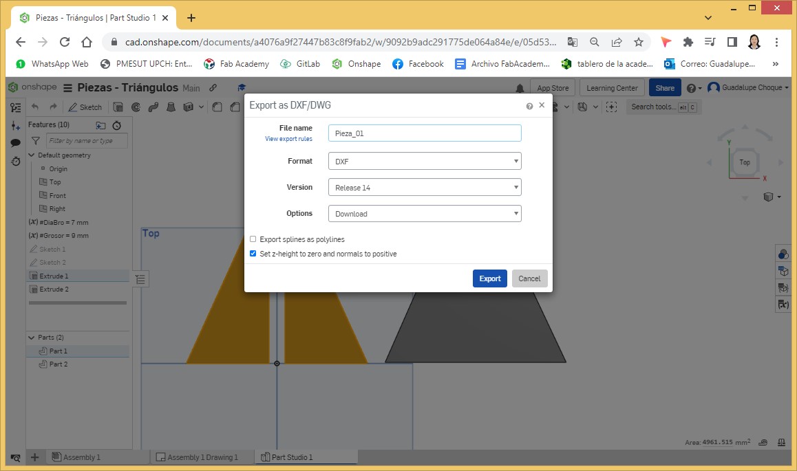
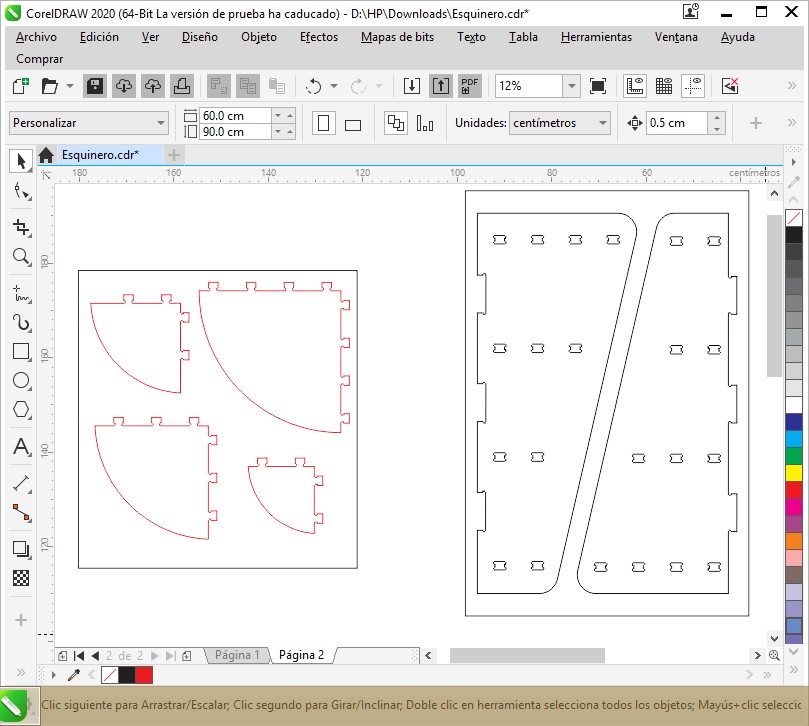
DWG files are loaded into Corel before cutting begins.
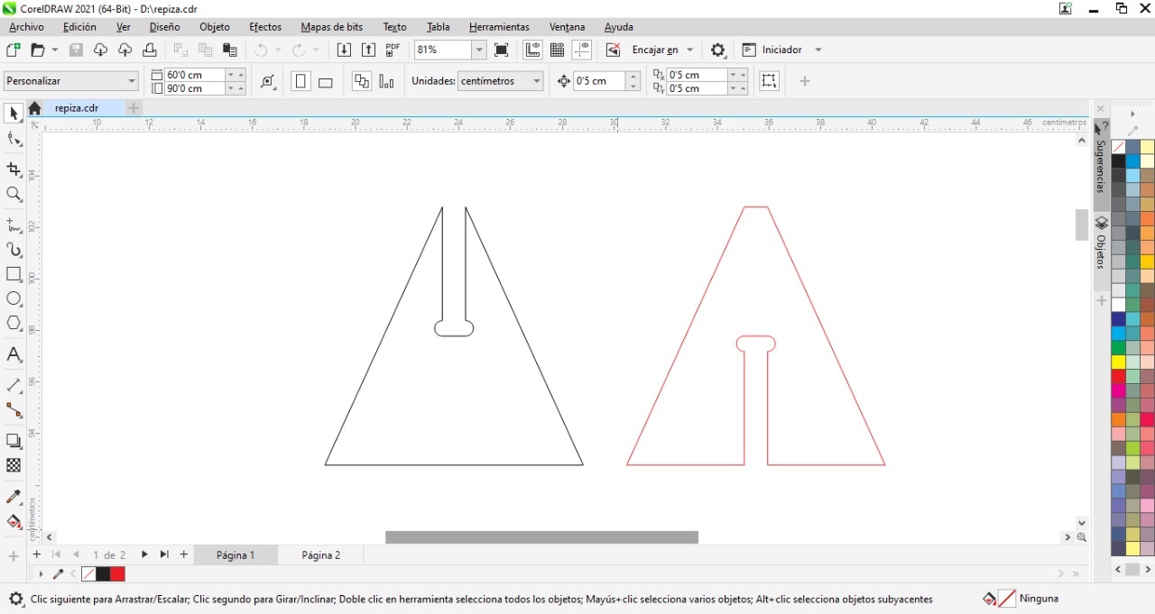
The Corel file is then loaded onto the machine (Blue Elephant CNC Router) and cutting begins. A video of the process is shown.
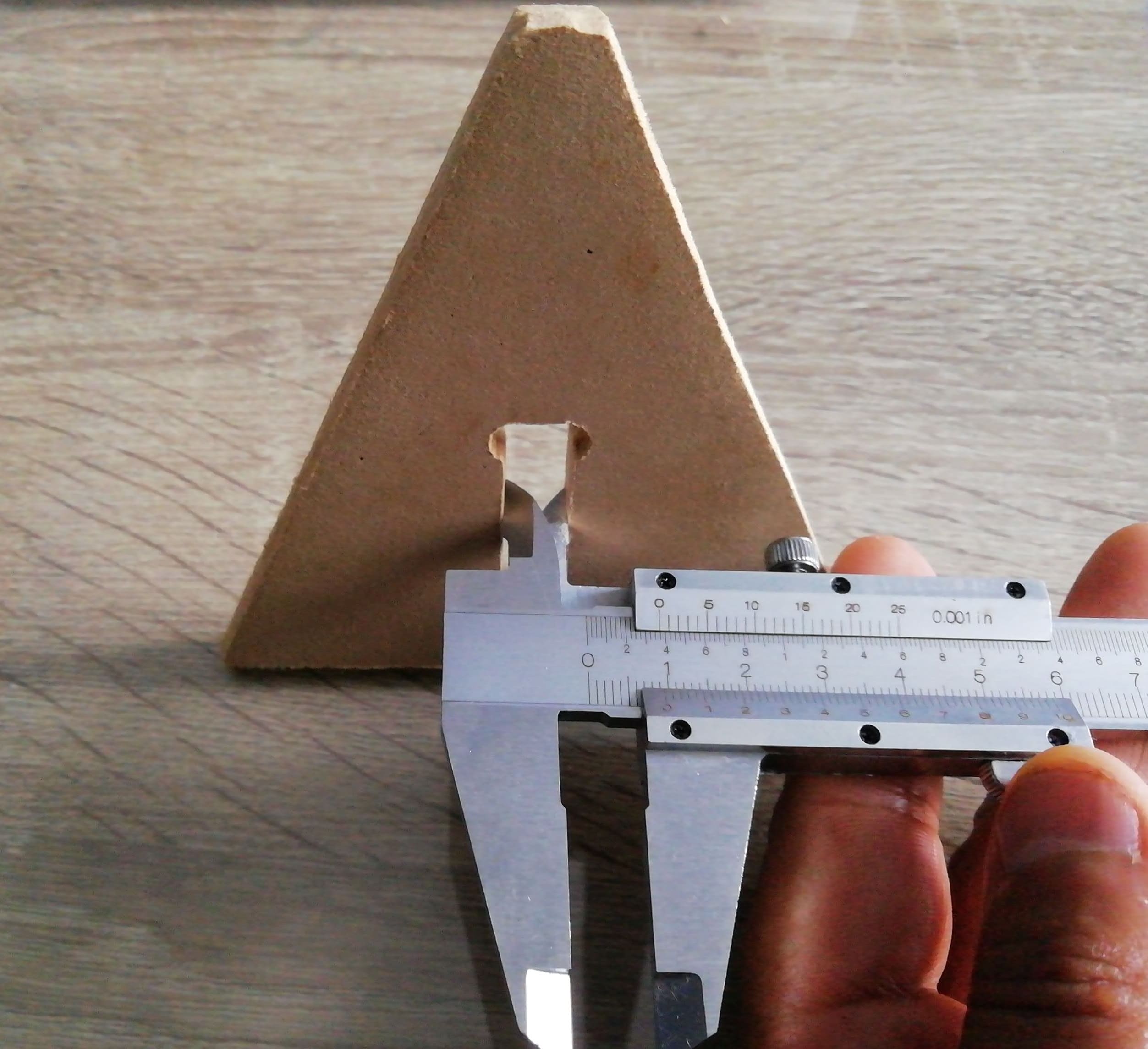
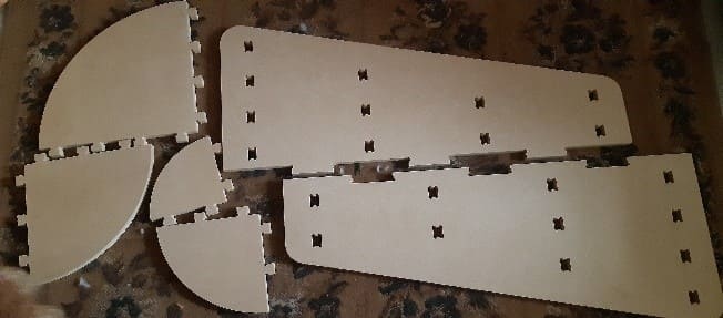
This is how the cut pieces look, after a smooth grinding and cleaning of the shaving hairs that are impregnated.
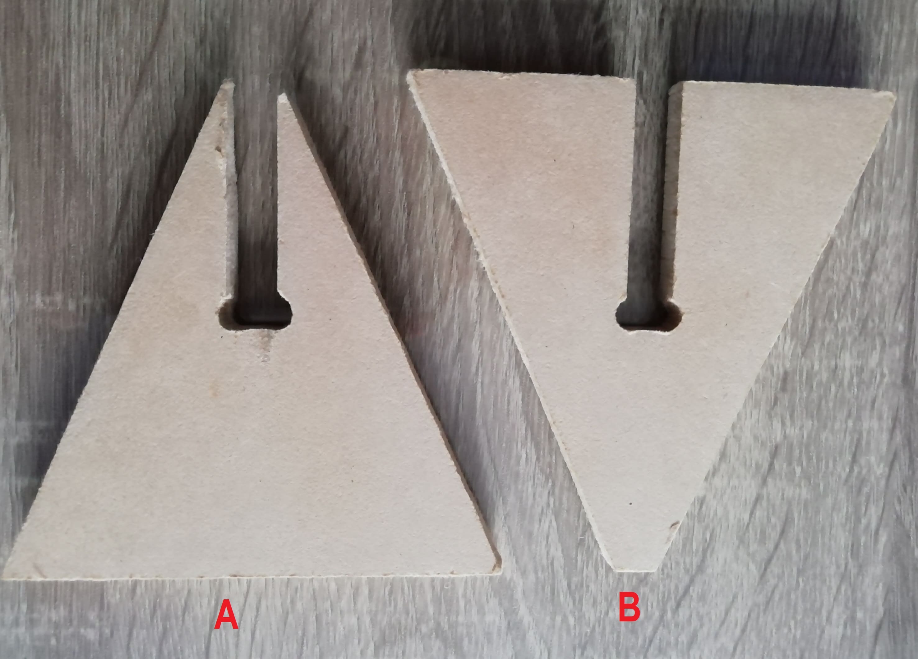
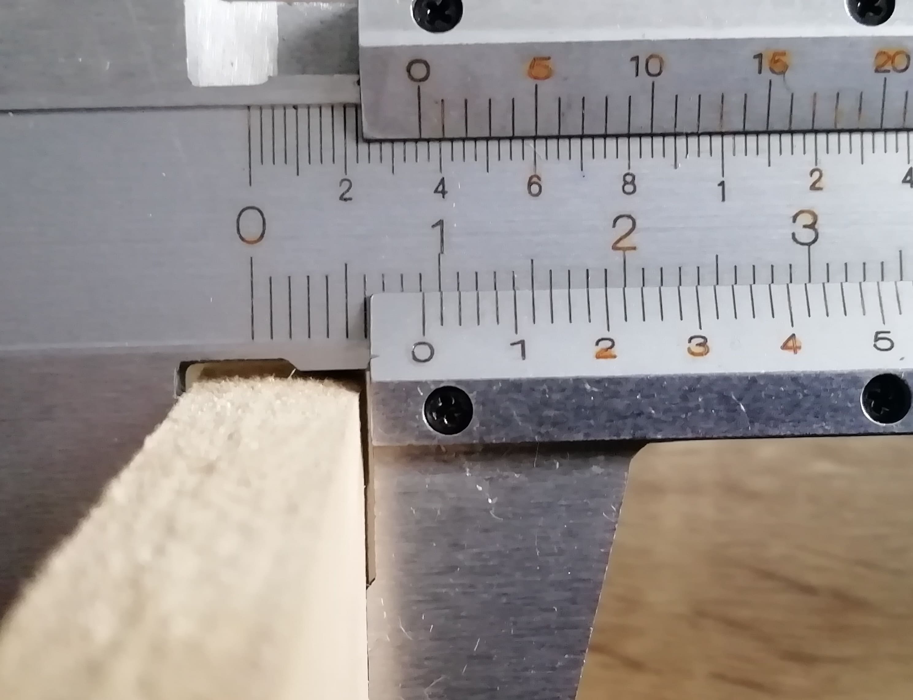
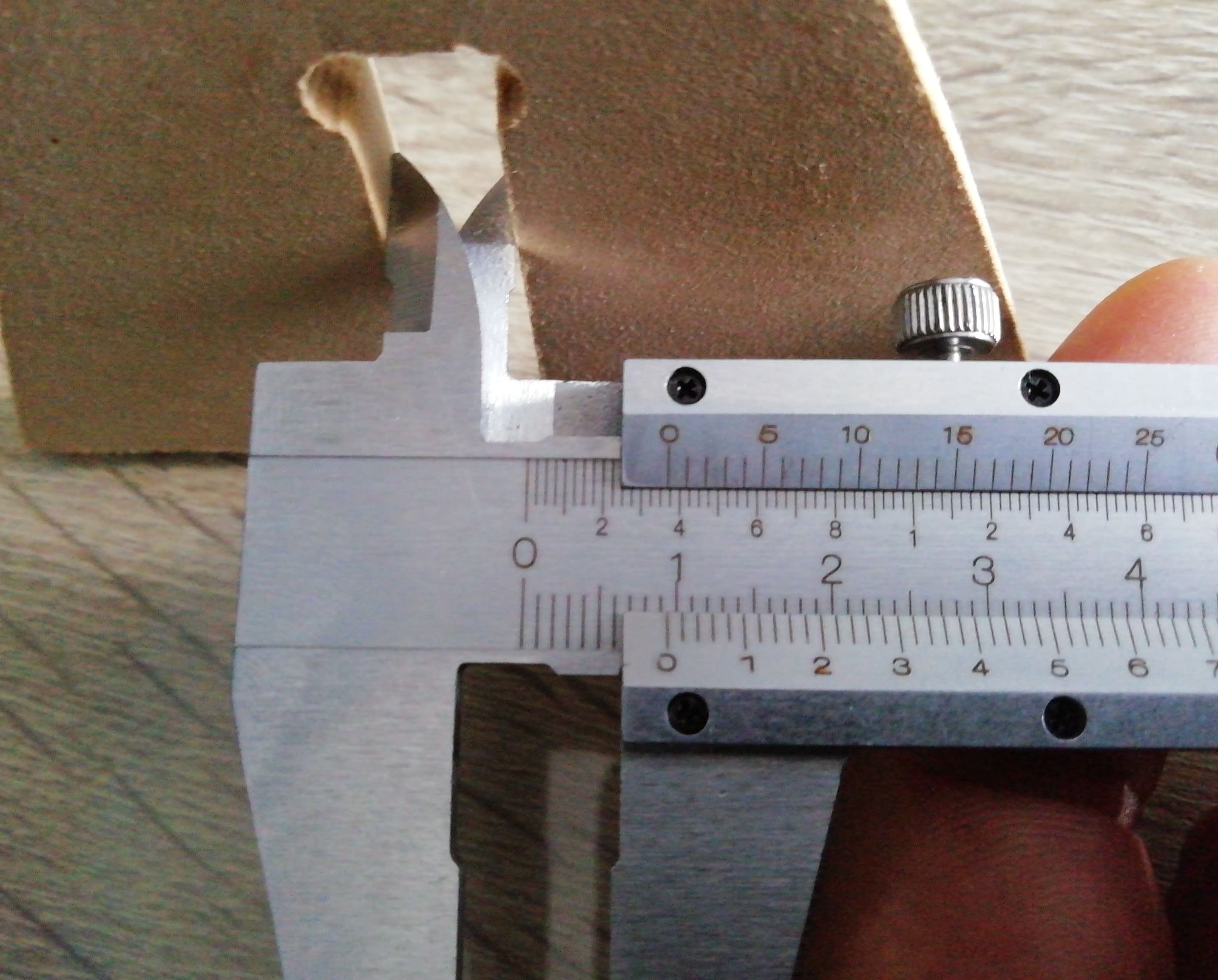
Then with the caliper we measure the slot of part A.
The measurement is 9.4 mm
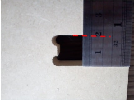
Then with the caliper we measure the slot of part B.
Slot measurement is 9.4mm
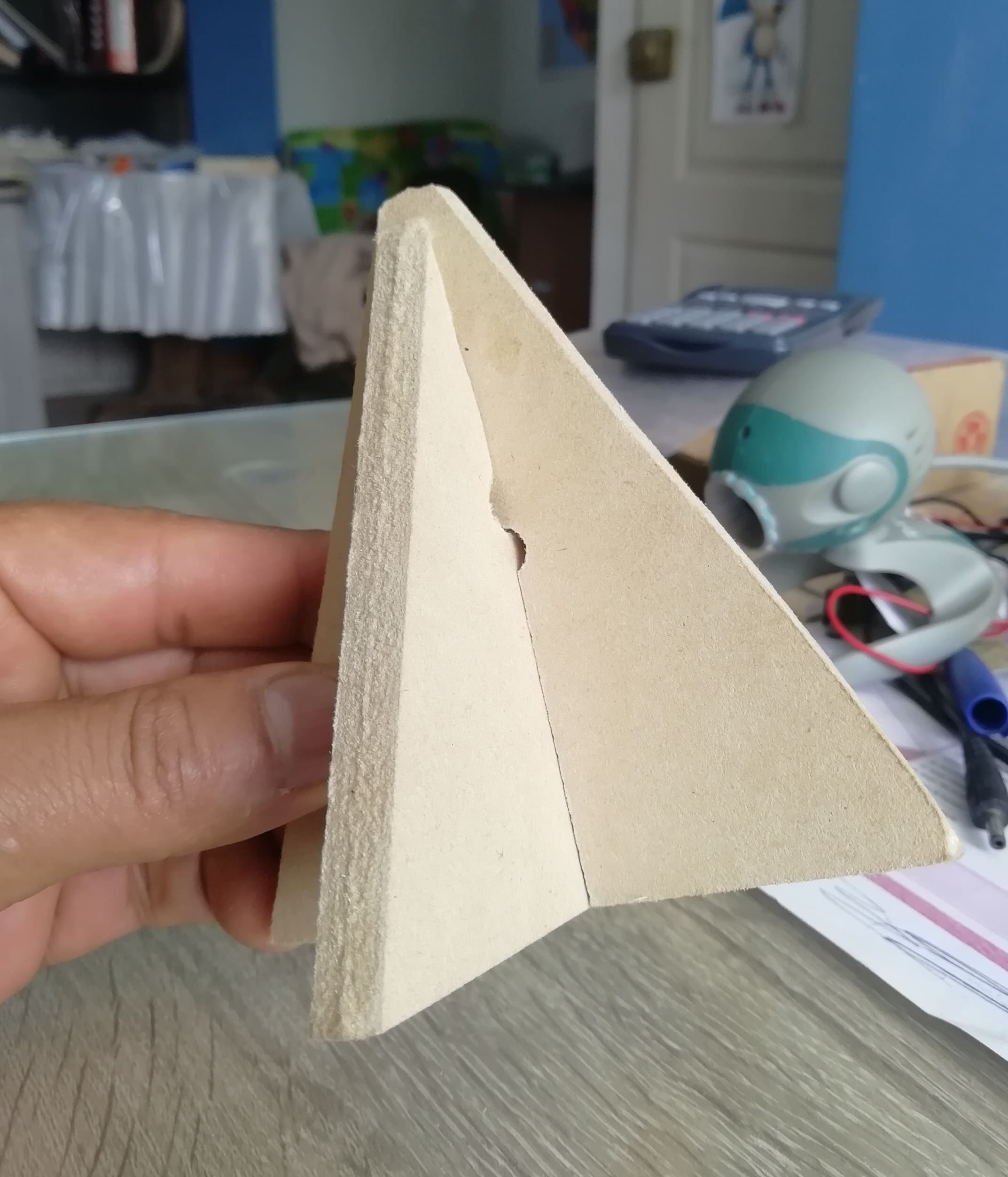
We proceed to join the pieces
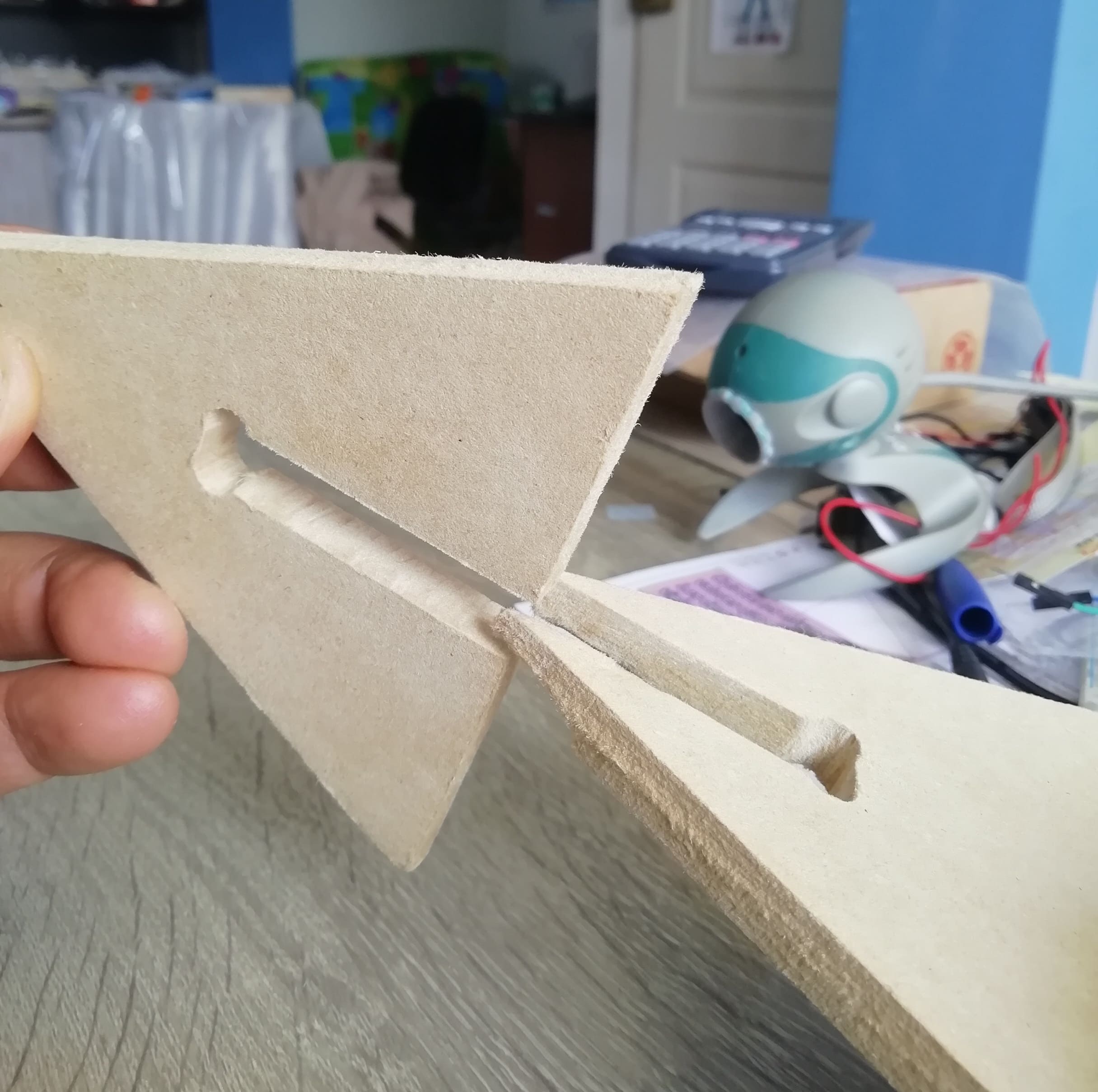
Leaving both pieces perfectly united
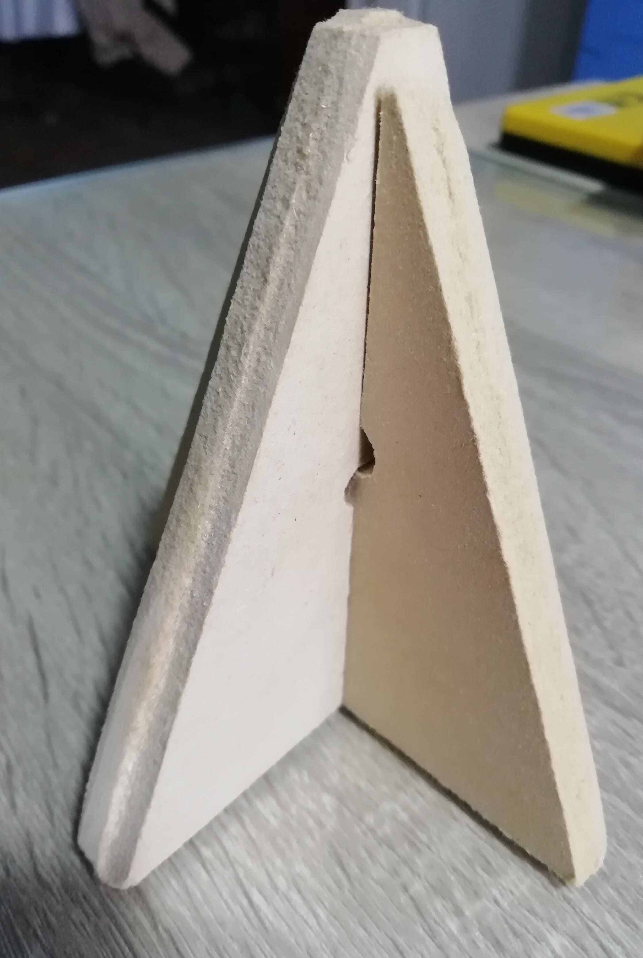
This is a bottom view of the tolerance test.
We see that the tibon are superimposed one on top of the other as it should be.
Individal Assignment
Good practices in a digital manufacturing laboratory
In all digital manufacturing laboratories, the following Good practices must be considered:
- Every person who works in the laboratory, whether or not they participate in procedures involving risk agents, must be informed of the corresponding security measures.
- When finishing work, be sure to disconnect electrical appliances and close gas connections.
- At the end of a task or operation, collect materials, reagents, equipment, etc., to maintain order and avoid unnecessary accumulations.
- Avoid behaviors or actions that may jeopardize your safety and that of other users.
- In case of failure or doubts in the use of equipment, consult the person in charge.
- It will not be possible to extract tools or supplies belonging to the Laboratory.
- The workshop is for public use and it is a common responsibility to keep the machines in good condition.
- Be willing to share experiences and skills in the use of equipment with other users.
Among the heaviest equipment in the digital manufacturing laboratory of the IES Francisco de Paula Vigil, is the FOX CNC milling machine.
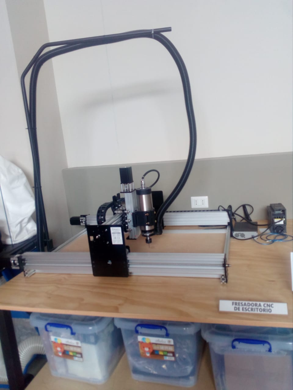
A CNC milling machine is a machine tool for carrying out machining work by chip removal through the movement of a rotary tool with several cutting edges called a milling cutter. Computer Numerical Control (CNC) milling machines allow programmable automation of production.
When working with this equipment, the following safety measures should be considered:
- Do not lean on the machine.
- Never put your hands into the rails with the machine turned on or lean on the movement axes of the milling machine.
- In the event that the machine makes unscheduled movements, the tool, chuck or work bridge is blocked, press the emergency button or disconnect the machine.
- Inside the milling room, use ear protectors and safety glasses.
- Maintain a safe distance from the bridge, anticipating its movement and work movements.
- If there is any problem or doubt, ask the laboratory staff.
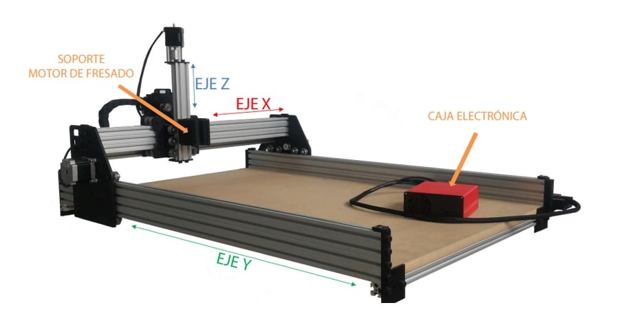
Safety precautions in a digital manufactuting Lab
− Never manually manipulate the machine or get in the way of its movement. The axes of the FOX CNC router have enough force to do damage.
− Always keep the milling motor off until you start working.
− Use parameters (feed speed, motor revolutions per minute, penetration per pass, etc.) suitable for each material and tool. Possible effects of inappropriate parameters:
Breakage of strawberries and tools
encystments in the material
Overheating and burning of materials such as wood or plastic.
− Prepare and review the programs well before sending them to the machine. It is recommended to do a vacuum mill before placing the material for extra verification.
− It is extremely important to have a good grip on the material to be milled at the base of the machine. If it is released in the middle of a job, the result will be wrong and can be dangerous.
Maintenance
The FOX CNC milling machine will remain in optimal conditions of use as long as these operations are periodically verified:
− Always clean the chips generated during milling. Take special care if said chips can hinder the movement of the axes.
− The FOX CNC milling machine comes from the factory with a MDF board as a martyr. Periodically check its condition and replace it when it is deteriorated.
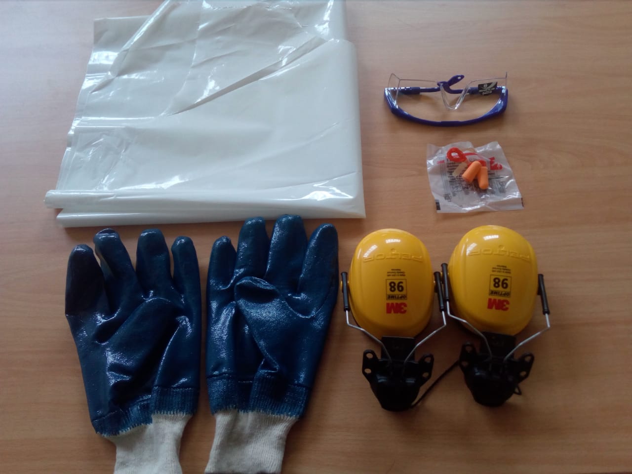
To carry out any of these tasks, in our digital manufacturing laboratory we have the following security implements:
- Earmuffs for hearing protection.
- Eye protection glasses.
- Disposable foam earplug.
- Cotton work glove with nitrile coated palm.
- Polyethylene apron T/poncho
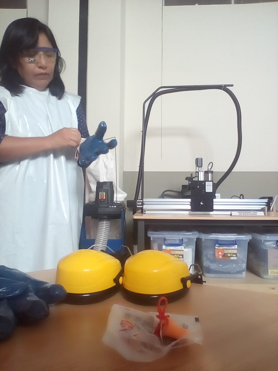
Using any of the security implements:
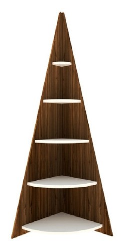
For the development of this individual work, the elaboration of a corner was considered, similar to the one shown in the following image:
According to the spaces where the corner post would finally be placed, it was considered convenient to work with a smaller, narrower one with fewer levels. A corner that would have an approximate height of 80.5 cm. x 33.6cm. wide per side. The four levels would be separated vertically by 23 cm. The first and last level will have a 5cm separation with respect to the outer edges of the corner.
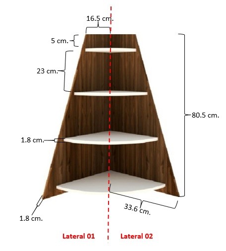
Given the inquiries made, it was advisable to make the corner in MDF material with a thickness or thickness equal to 1.8 mm.
In the same way as in the group work, I requested the cutting service from third parties, who, after consulting me, told me that a drill with a diameter equal to 0.6 cm would be used for cutting. Very important data to be considered in the design.
Regarding the design, knowing how friendly it is and the benefits of its resources, it was considered convenient to use Onshape as CAD 3.
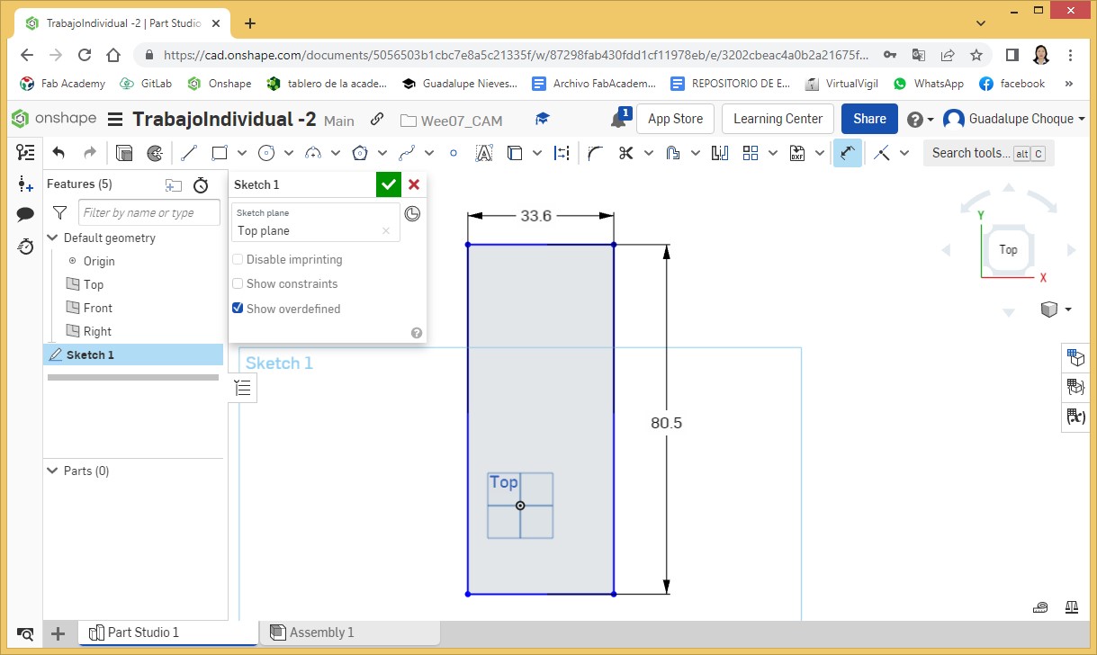
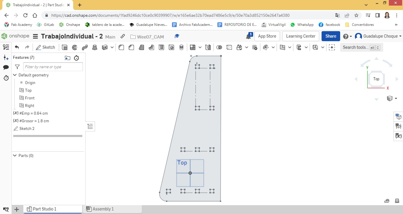
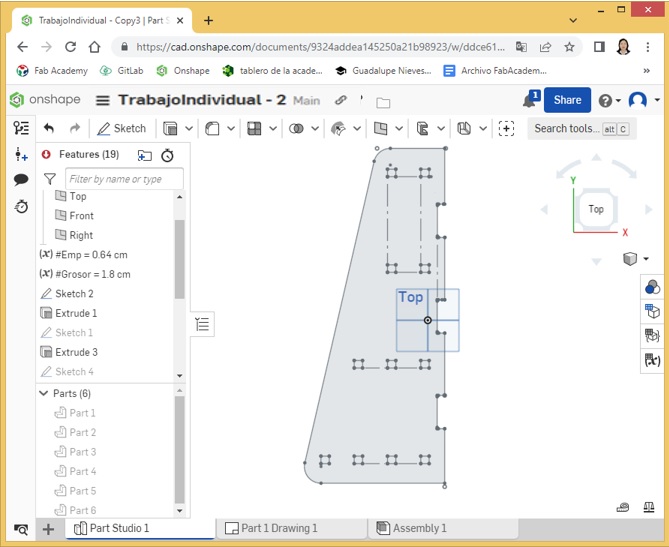
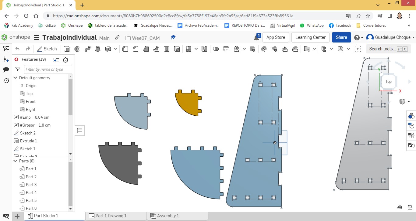
Finding myself in the software, I proceeded to design the first side. For this first part of the design I inserted a 80.5 cm rectangle in the first Sketch. x 33.6cm.
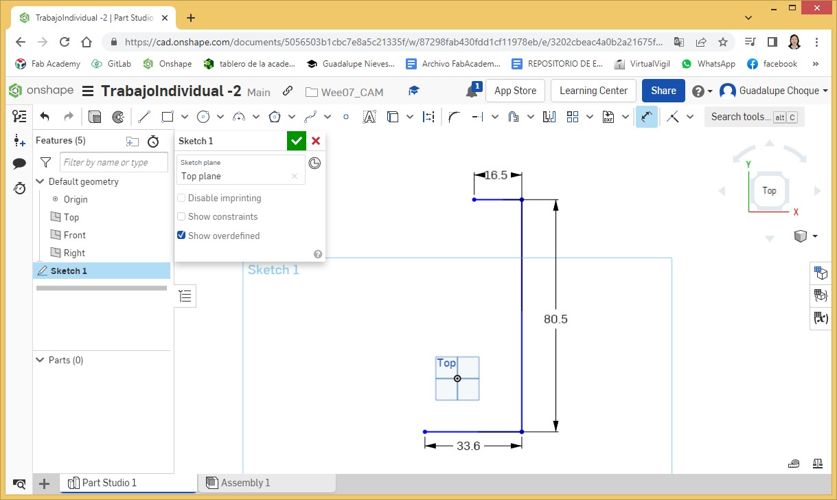
From the inserted rectangle, I made an edit to it to give it a similar shape to the model. To do this I insert nodes with the Split tool at the top, and from there I make the cuts with the Trim tool.
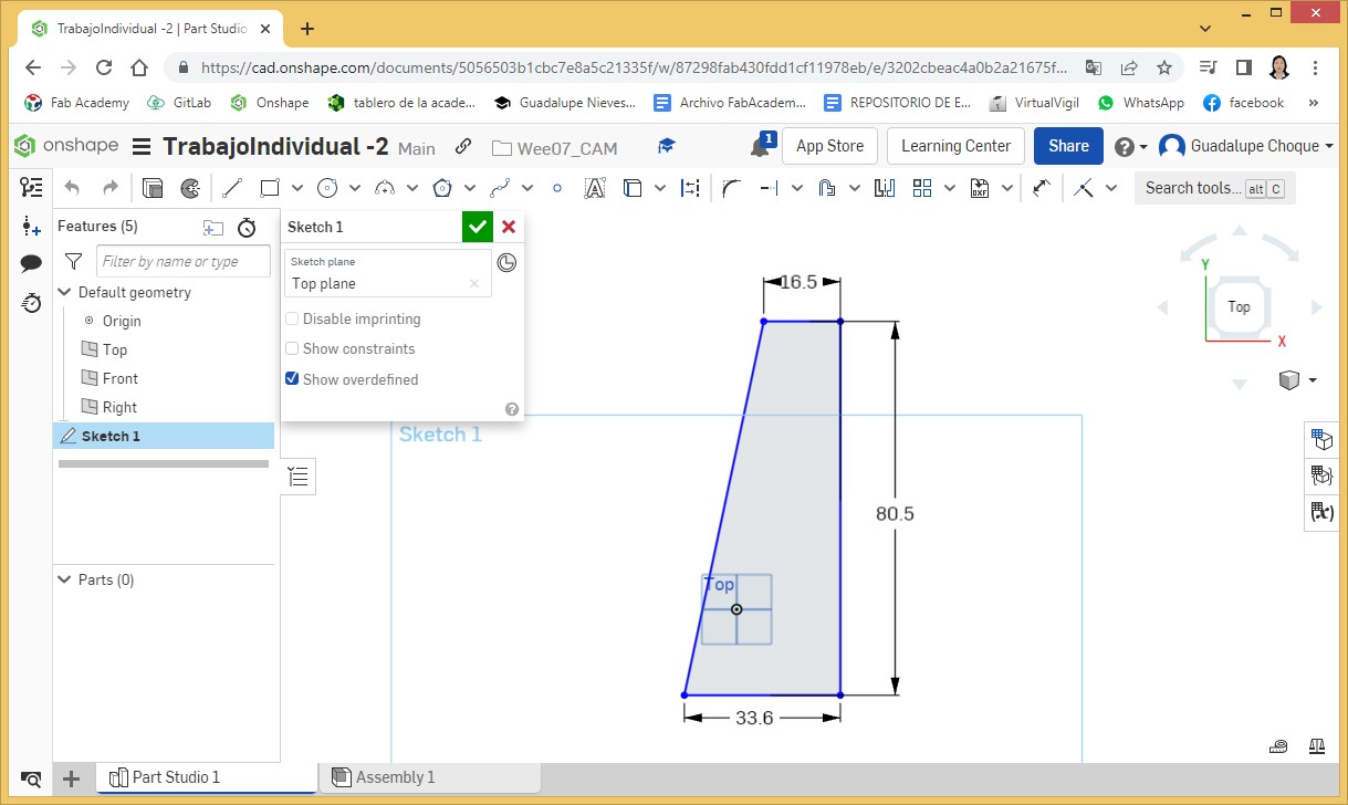
I insert a diagonal line to join the separation nodes.
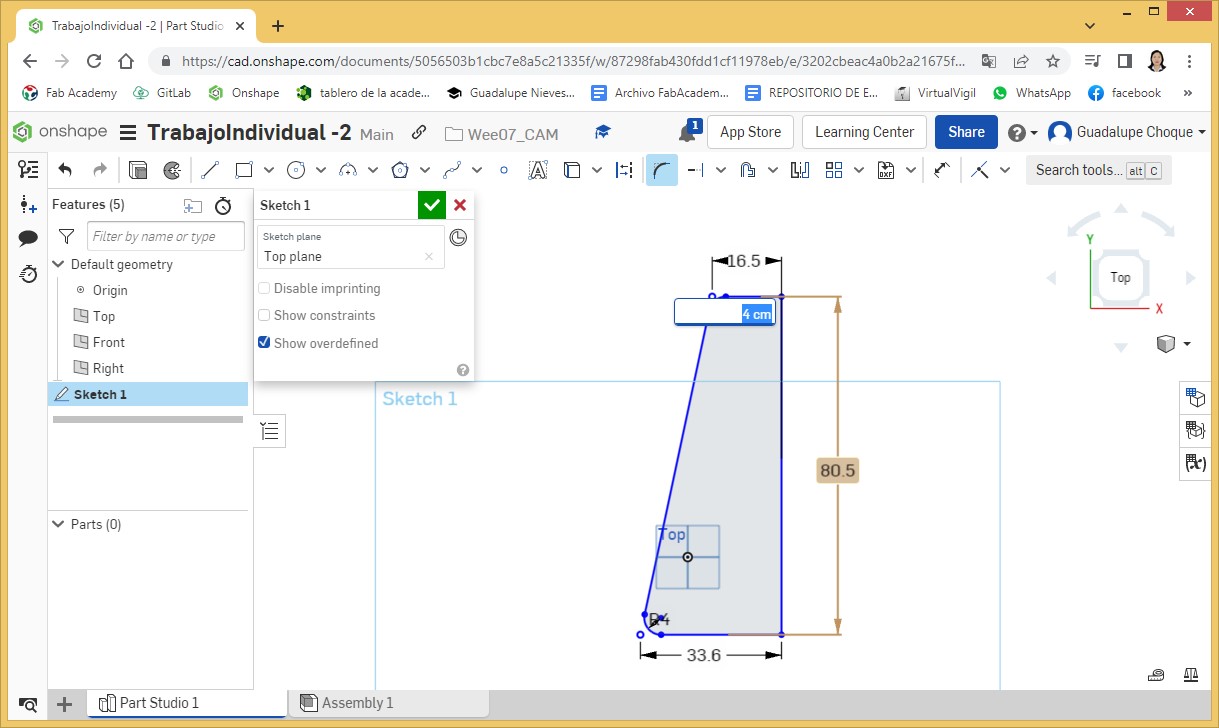
Now I proceed to round the corners, on one side, to 4 cm. radio This is done for the top and bottom of the side.
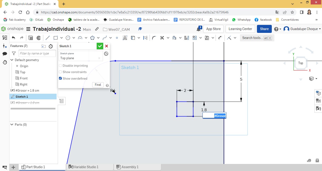
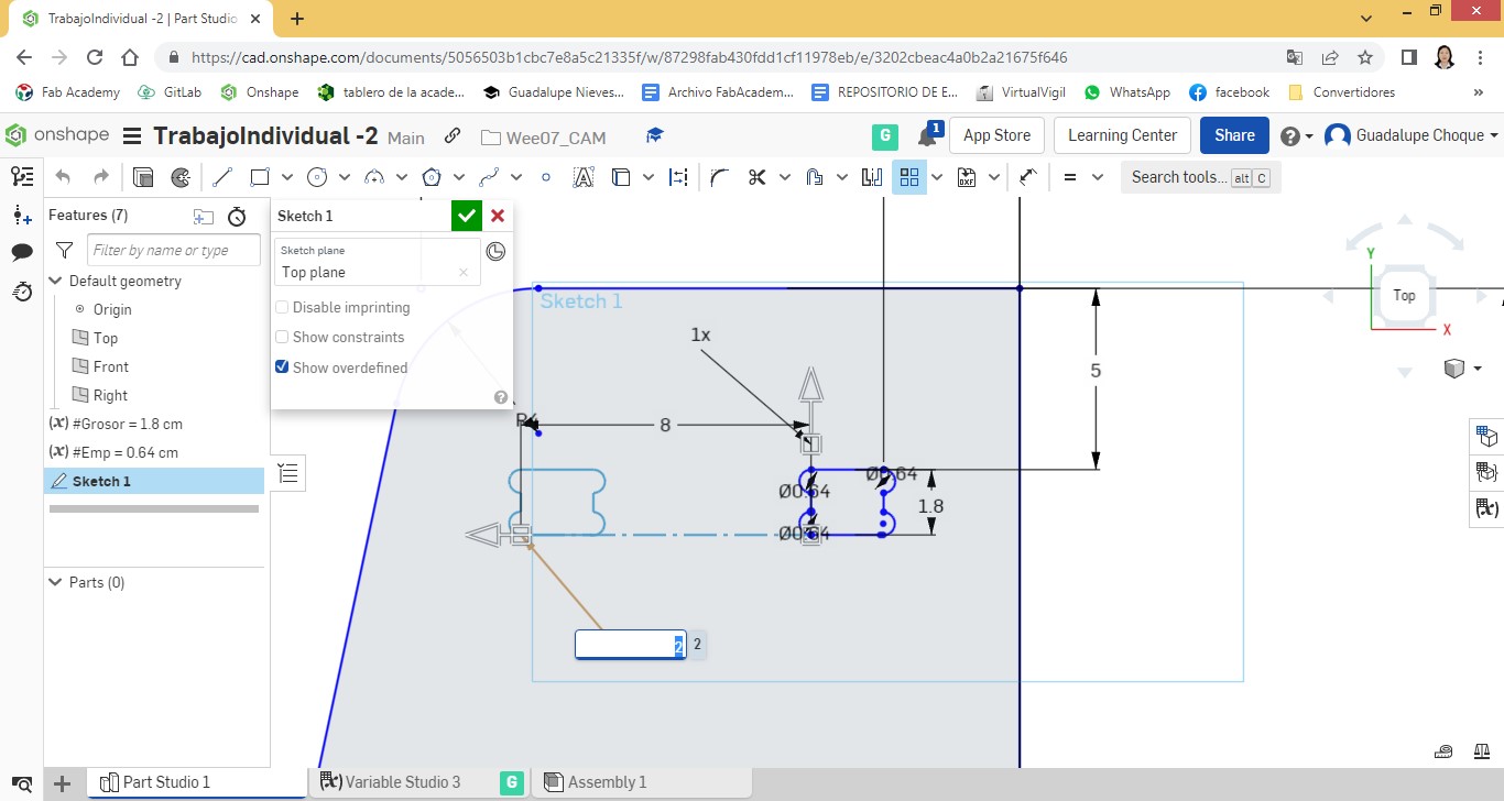
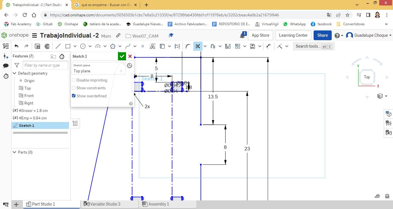
Taking as reference the straight part (right) of the side, at 5cm. from the top edge and 3.75cm. From the edge on the right, I draw a first hole, 2 cm. x 1.8cm. (Thickness).
As the thickness value, which is the thickness of the material with which the cut is going to be made, we work with it as a constant value assigning it to the variable #Thickness (Parametric Design).
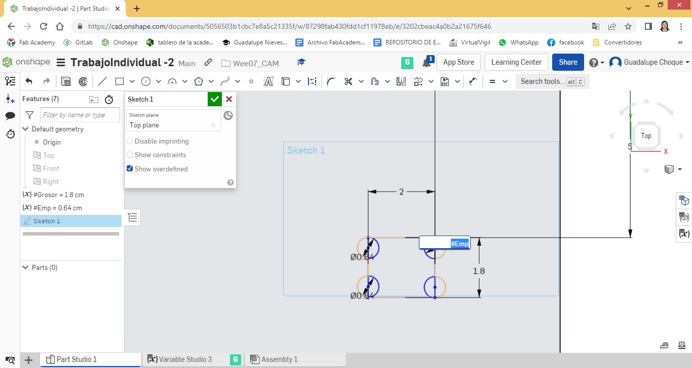
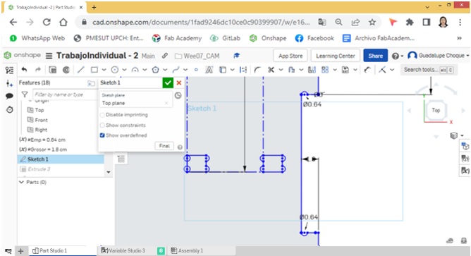
Now so that the router bit cuts without any difficulty, I prepare the corners of the rectangle, inserting circles with diameters of 0.64cm. (The diameter of the drill bit is 0.6cm). In the same way, I apply parametric design for the value of the diameter of this circumference. I create the #Emp variable and assign it the value of 0.64cm.
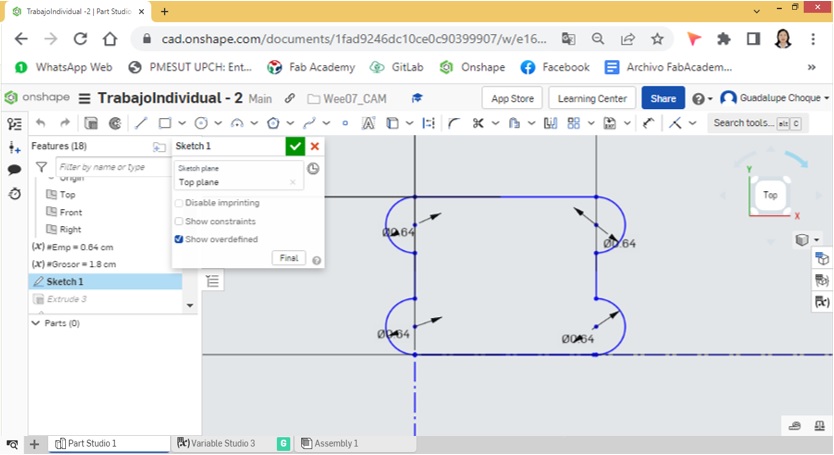
I perform the drilling by making cuts.
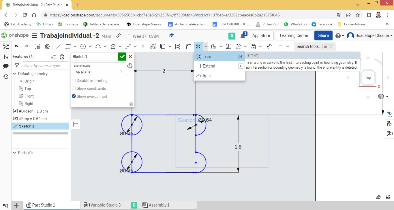
Finally, the design of the part looks like this:
What I now do is duplicate the hole, at a horizontal distance of 8cm.
These holes would serve to connect with the entrances of the first level.
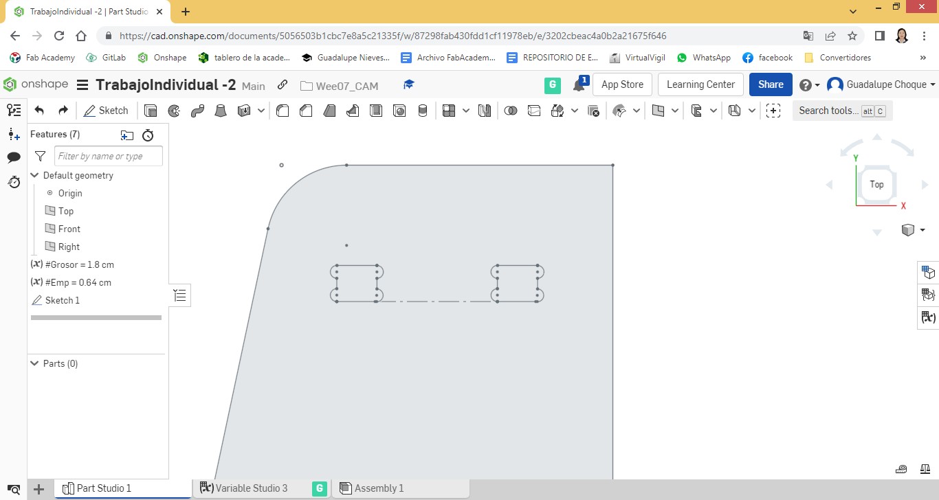
Similarly, the hole was quadrupled vertically, according to the number of levels.
Showing what has been worked.
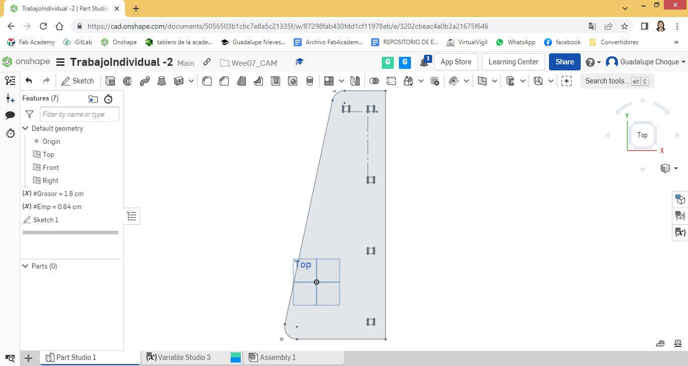
The same treatment was performed with the hole in the first column on the left. In the case of the third and fourth levels, due to their greater width, a horizontal duplicate was made on the third, while a triplicate was made on the fourth.
Before I trace the splice entries and/or exits, I add a second Sketch and make a copy of the trace.
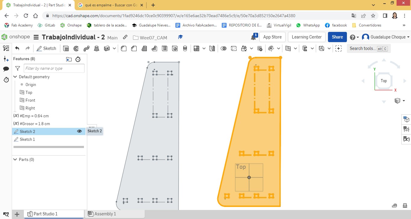
On one side I will trace splice entrances and on the other exits.
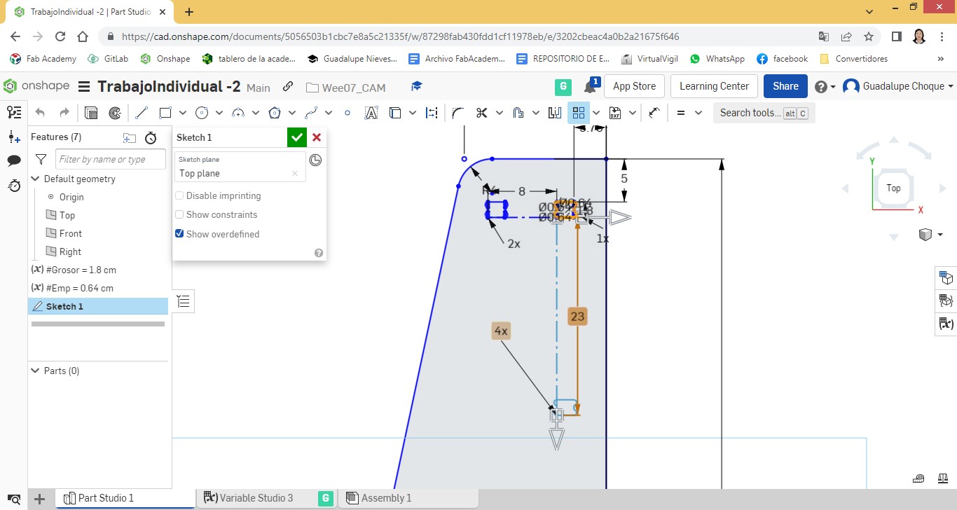
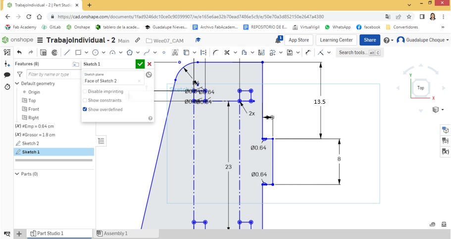
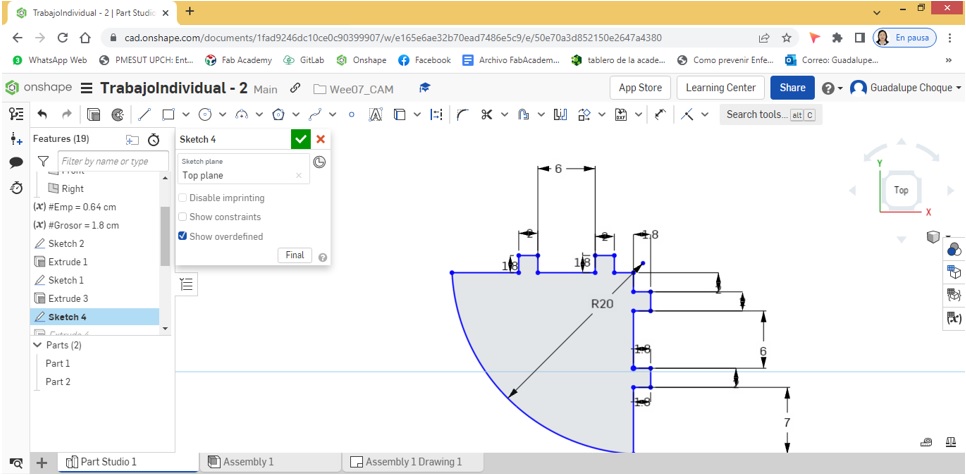
I start by working splice entries on side 1. Positioning myself on the right side of the side, at a distance of 13.5cm. from the upper edge, I insert a first node and another at 8 cm. from the previous one. Then I proceed to cut.
I make a new tracing through the cut area, taking as a reference the width of the MDF material at the time of milling; 1.8cm.

I proceed to insert semicircles in the four corners. for the use of the router bit.
The same procedure I perform in the following 3 entries. It has been considered as a distance between inputs 15cm.
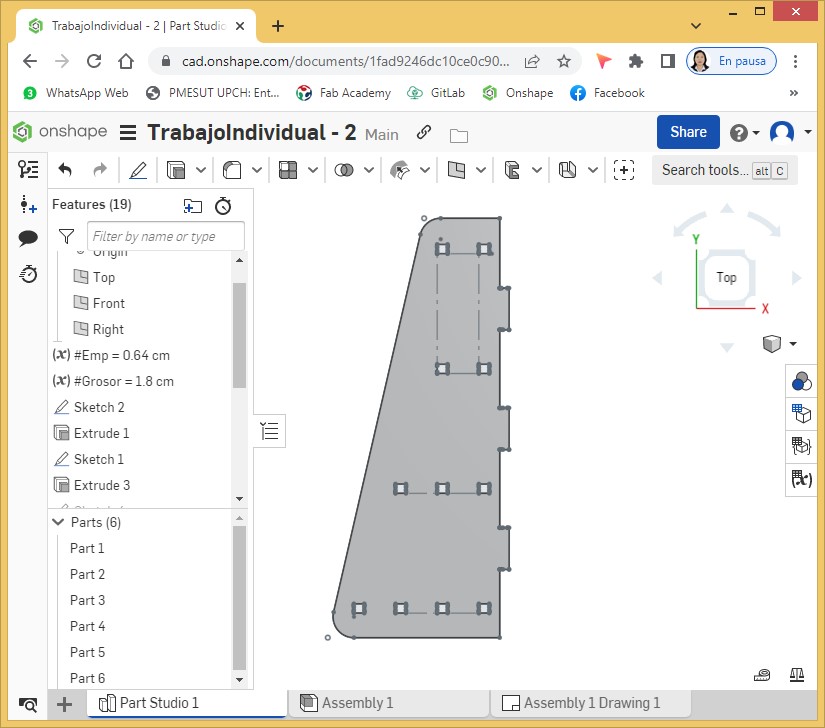
Completed with the design of the first side.
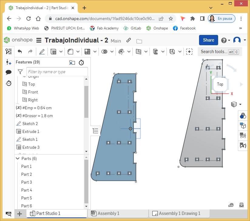
Now I start the work with side 2. Here we must work with outlets.
The tools used were the same as those used on the first side. The only difference is that the cuts were made in opposite locations to the first side.
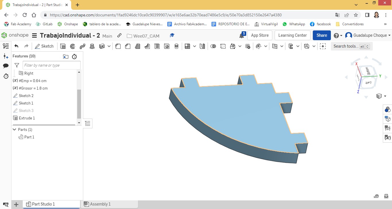
A view of the finished lateral2.
Applying an extrusion of 1.8 cm. to each side.
View from another angle.
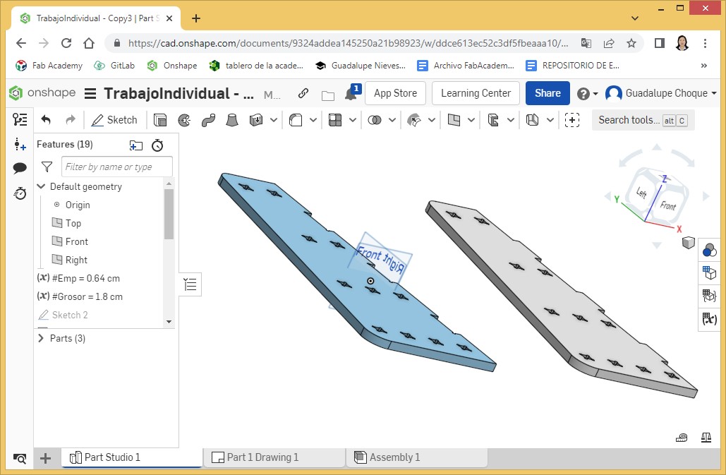
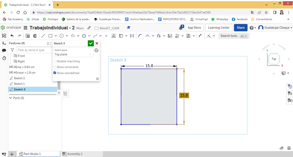
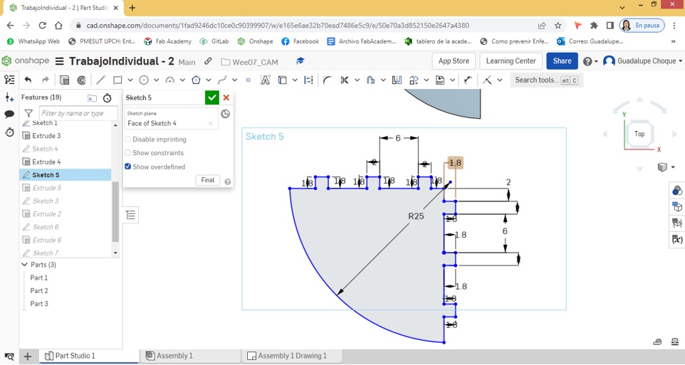
Then I continued with the design of the four levels. All levels have splice outlets. It began with the design of the first level, the smallest. I took as reference the measurements applied on the sides. It all started from a 15.8 cm. x 15.8 cm. square.
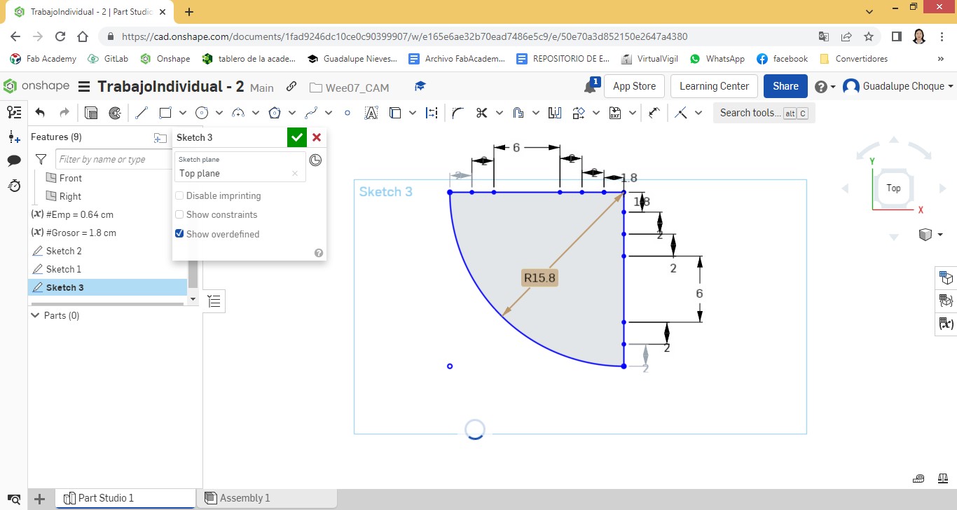
I applied Sketch Fillet between two sides of the square at a radius of 16.5 cm.
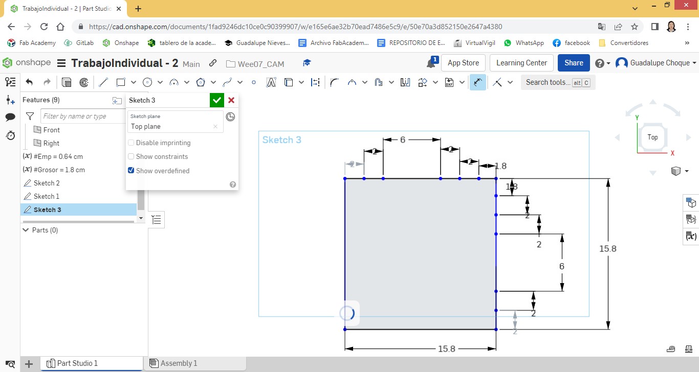
I insert nodes spaced according to the measurements given on the sides.
I insert a radius of 15.8 cm.
I draw two lines, horizontal and vertical, at a distance of 1.8 cm from the edge.
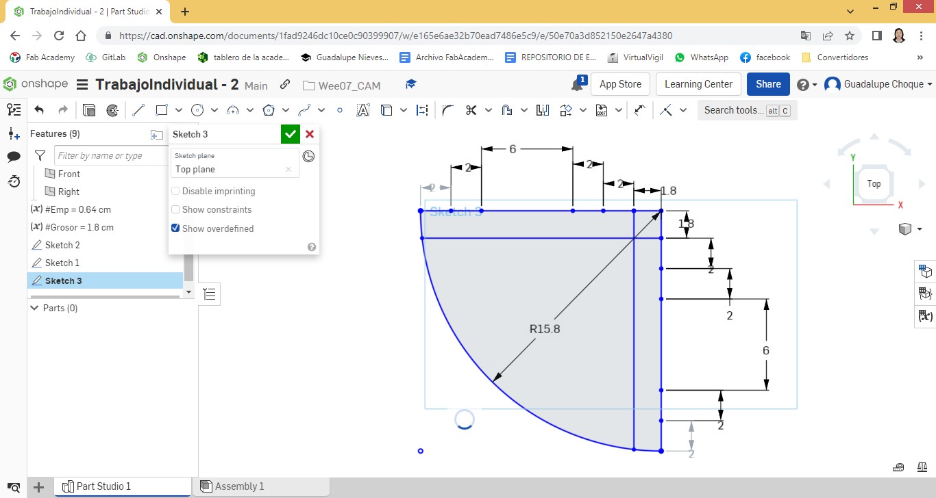
I draw lines perpendicular to the edges and matching the drawn lines.
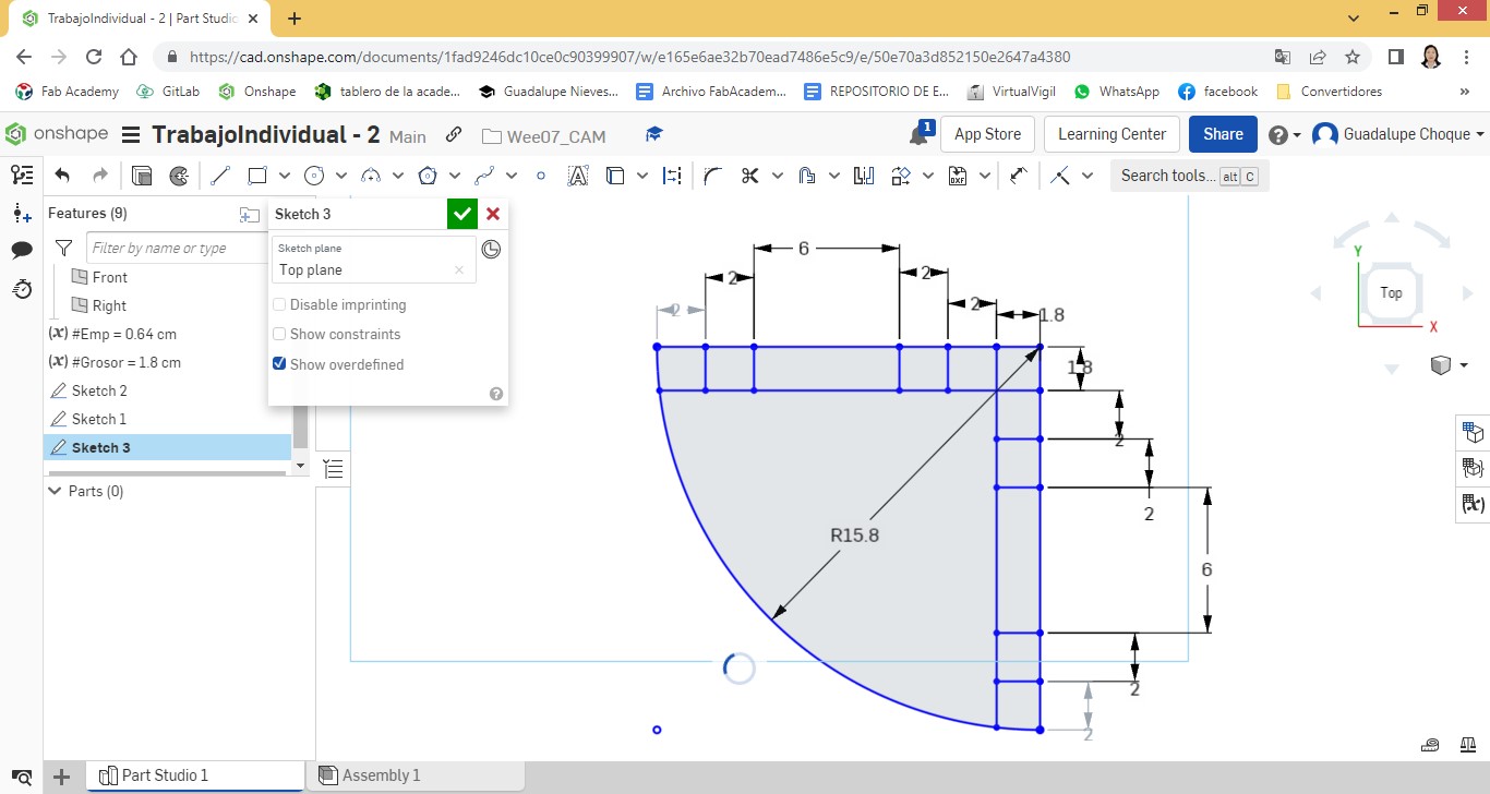
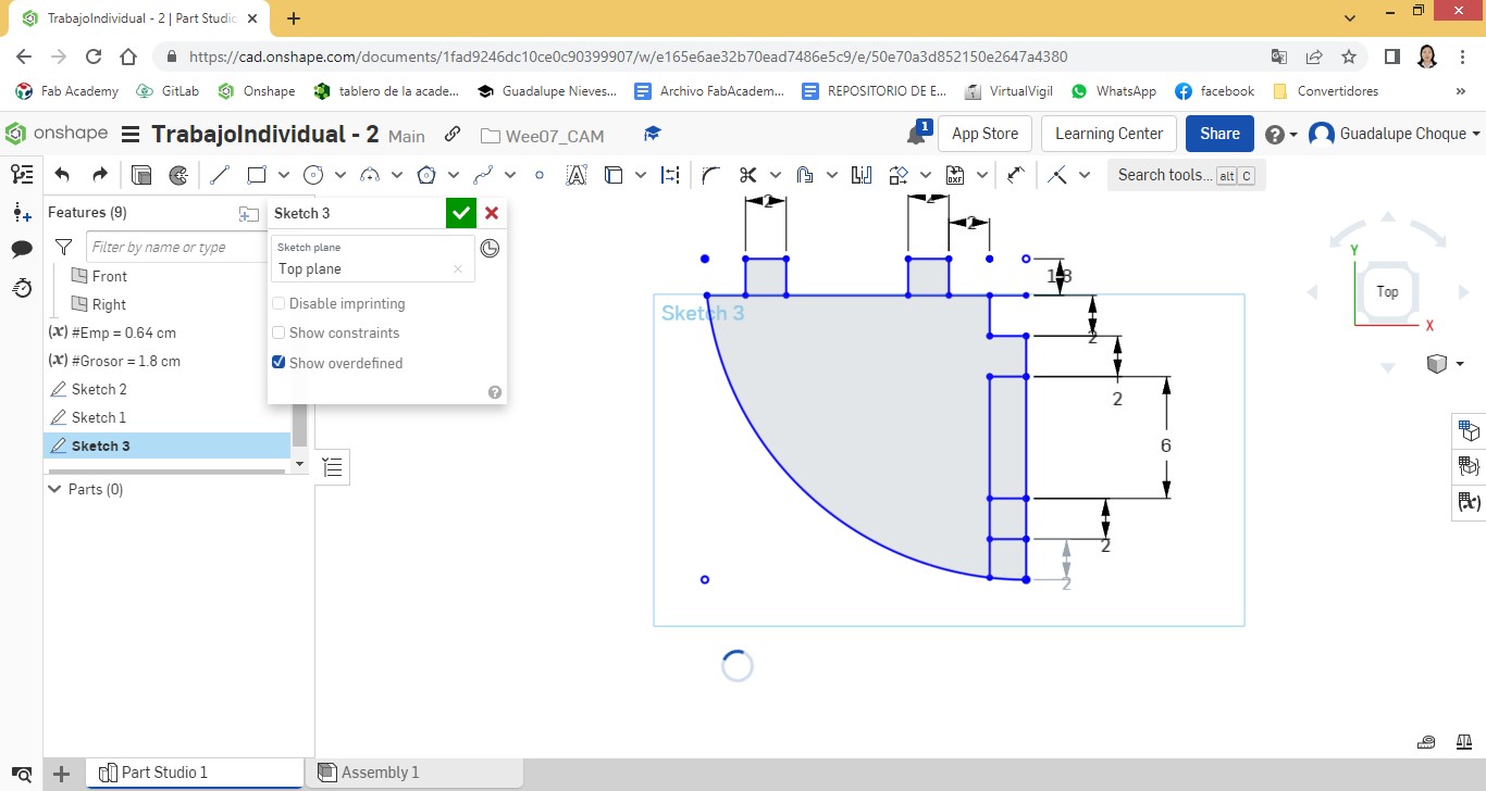
I start cutting and joining nodes, in such a way that there are two exits per side.
I give it an extrusion and assign the value of the variable #Grosor
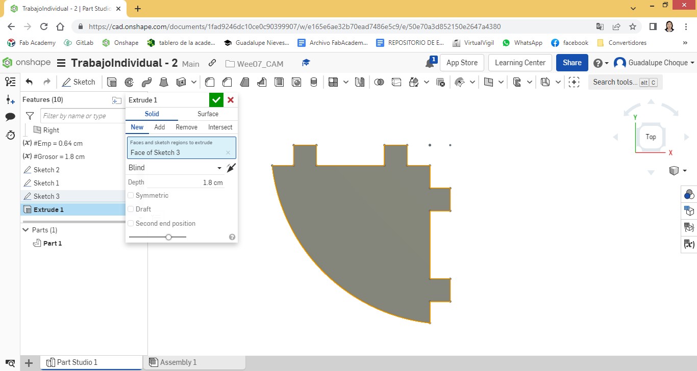
A view of the first level.
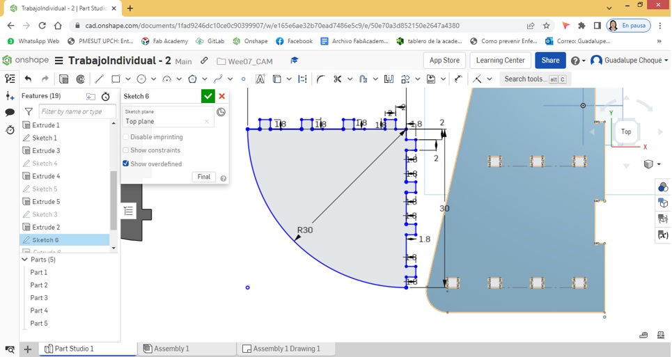
Considering the same procedure, I worked the other levels, always taking as a reference the measurements given on the sides.
The following corresponds to level two.
This is the result of what was worked on at level three.
And finally, those worked on level four are shown.
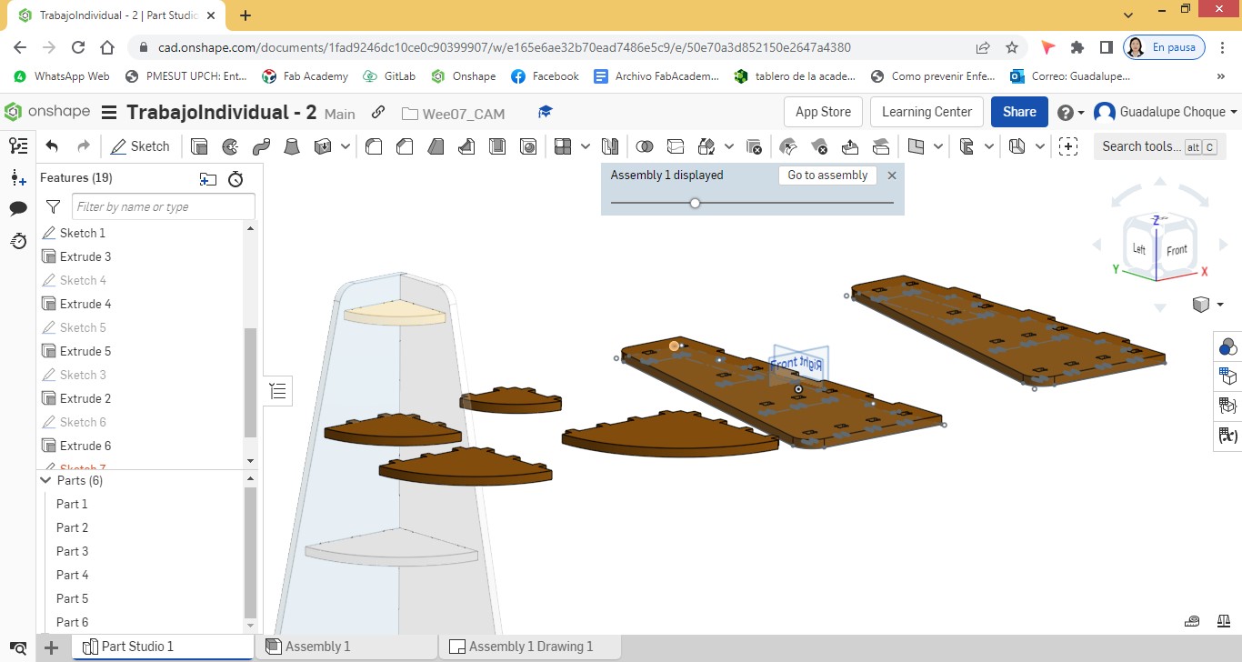
A view of all the work.
Locating ourselves in the Assembly area, we proceed to assemble the pieces.
For this we insert all the pieces in the assembly area and start assembling one by one.
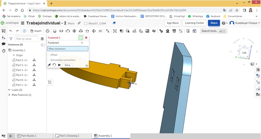
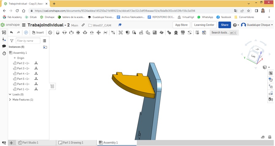
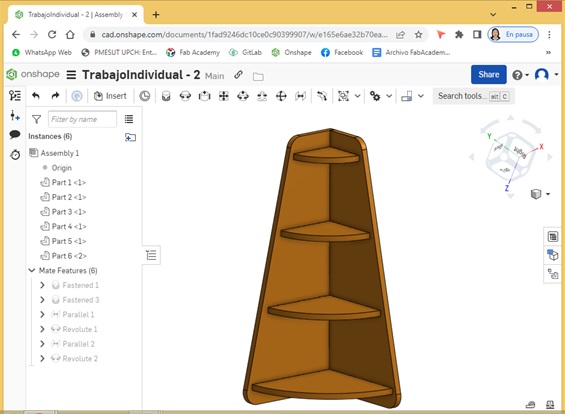
Once the assembly is finished, there is a simulation of what is going to be physically obtained later.
A uniform color was assigned to the entire corner, so that its similarity to the physical is as close as possible.
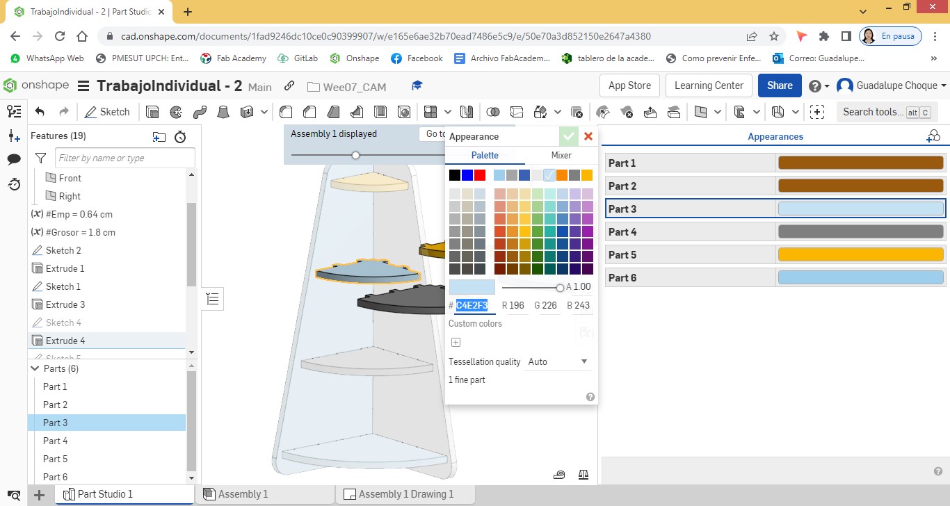
Using the color palette, all corner pieces are assigned a single color.
Simulating the physical cornerback.
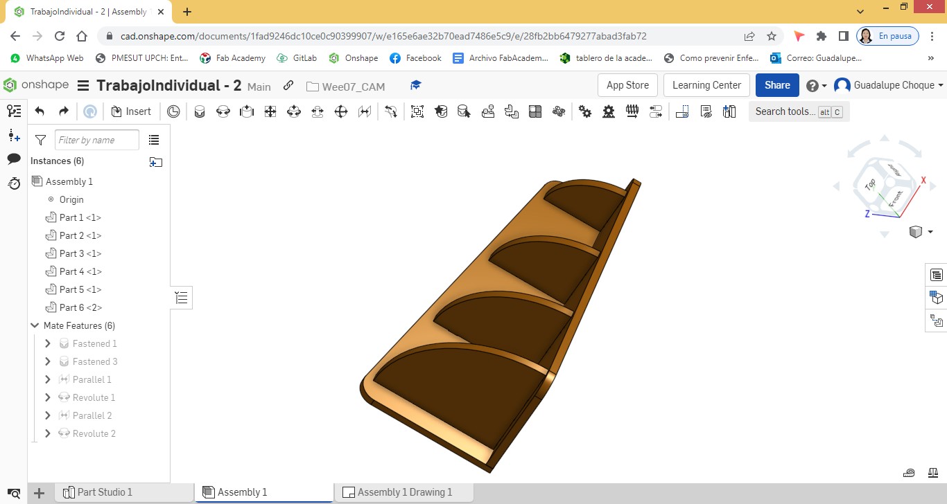
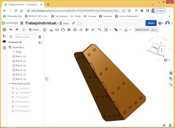
Views of the cornerpost from different angles:
The design was exported to DXF extension.
This file is the one that was delivered to the person who would be in charge of providing me with the service of cutting the parts of the corner with the help of a milling machine.
This file would then be retrieved and organized in Corel Draw, and then used by the milling machine.
The milling machine would use a 0.6 cm milling cutter. to make the cut in the 1.8 thick MDF material.
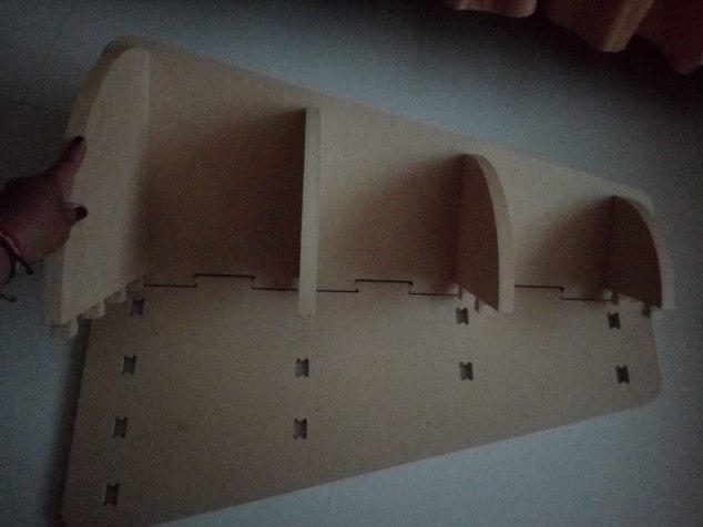
Once the cut was finished, the pieces of the corner were like this:
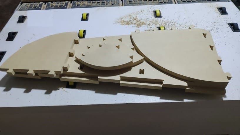
A view of the 06 separate pieces. Two sides and four levels.
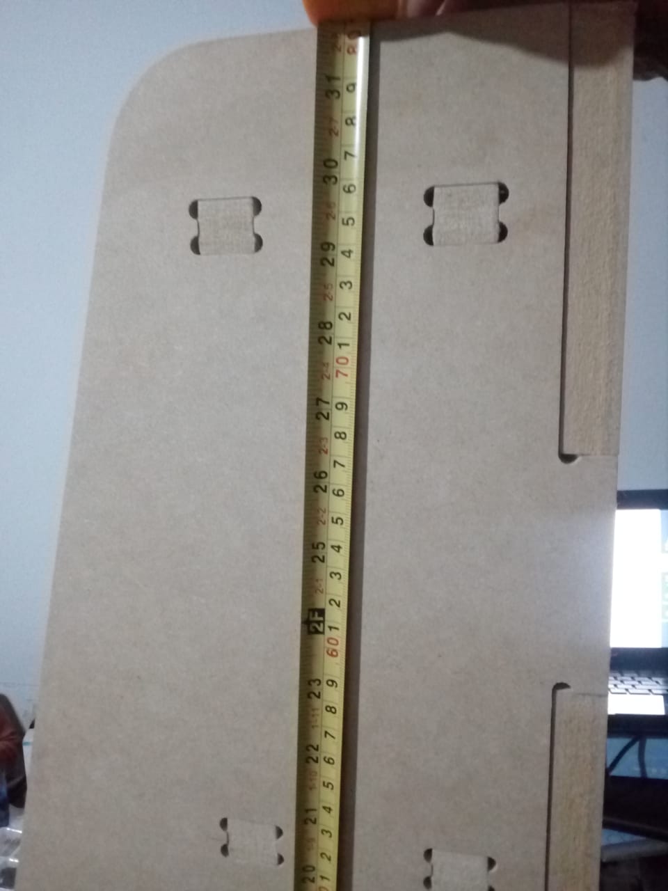
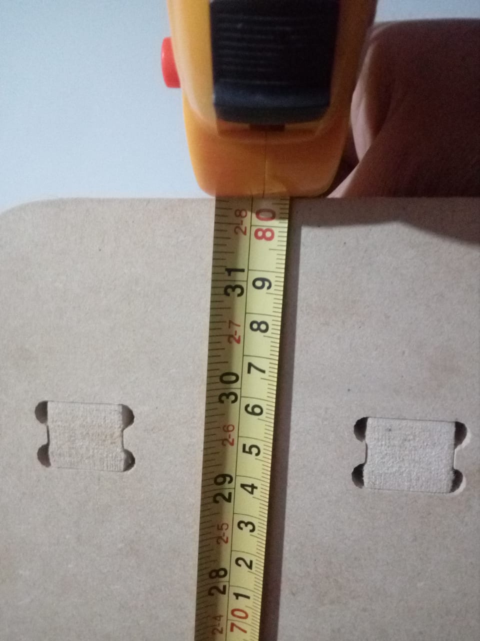
Checking the measurements of the joints
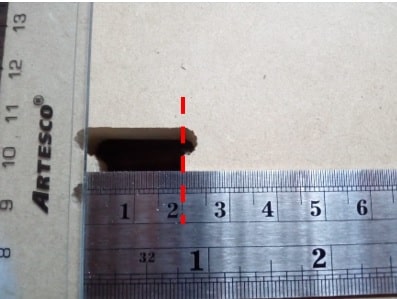
The width of the splice is 2 cm, as specified in the design. As well as the high; 1.8cm measure that had to match the thickness of the MDF material.
It can also be noted that the value of the radius is approximately 0.32 cm. The bur used for the cut was 0.6 cm. As a precaution, I assigned the circumference a diameter of 0.64 cm.
Arming the corner
I took one of the sides and the fourth level piece. I made the joints fit and did some pressure for a good set up. I did the same procedure for all levels.
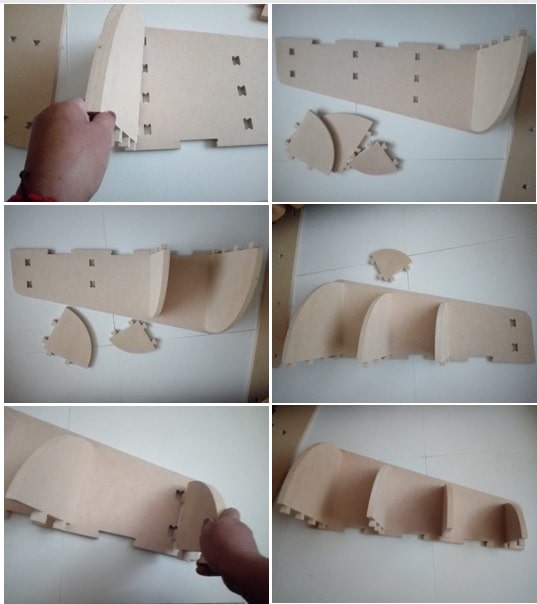
Finished with the assembly of the first side and the four levels, we complete it with side 2.
We seek to fit the joints.
We do some pressure so that everything is firmly assembled.
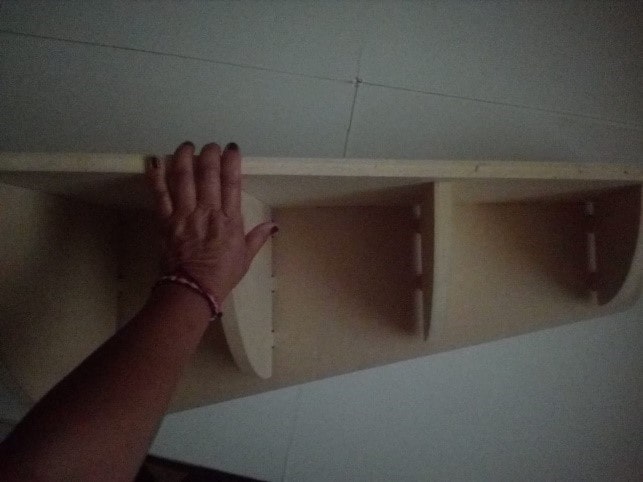
Checking the splices.
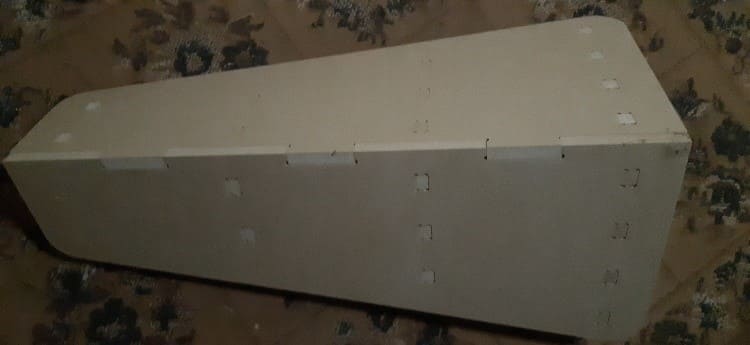
Checking measurements of the corner
Corner heigh
The height is 80.5 cm.
Cornerpost Width
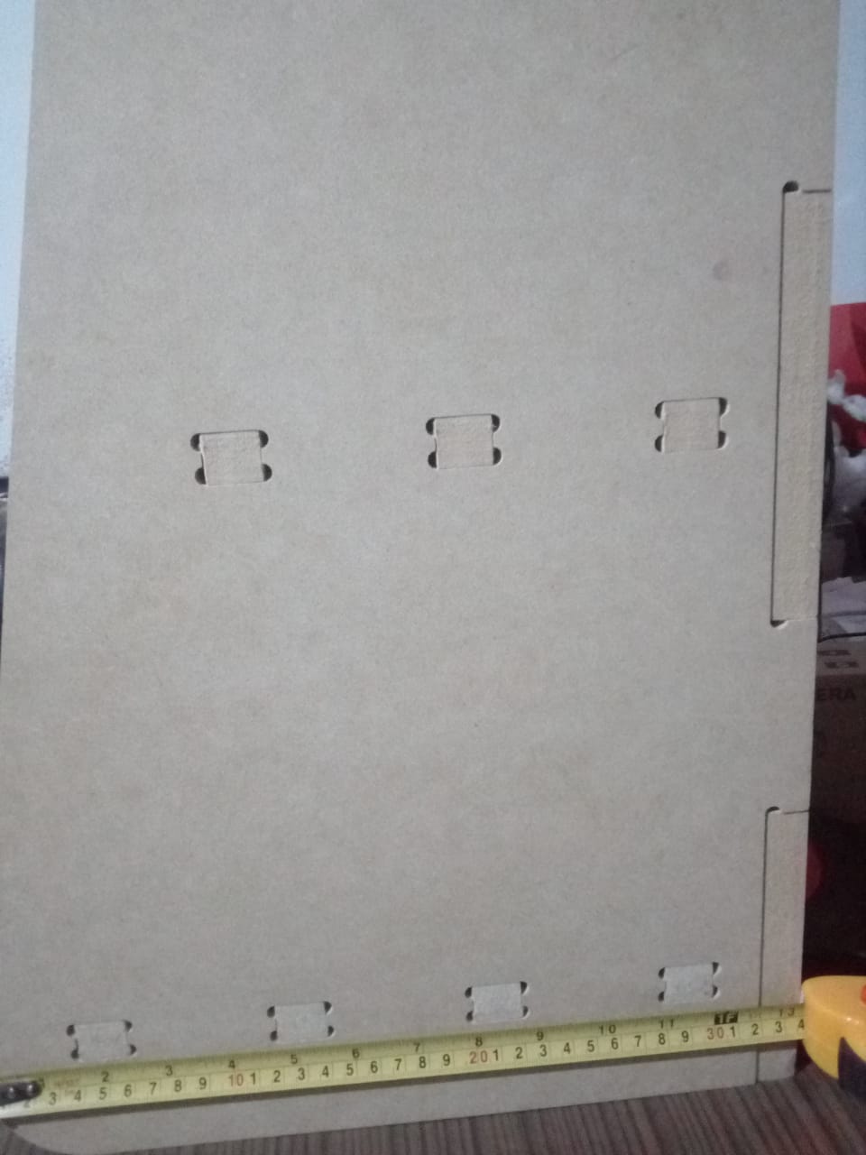
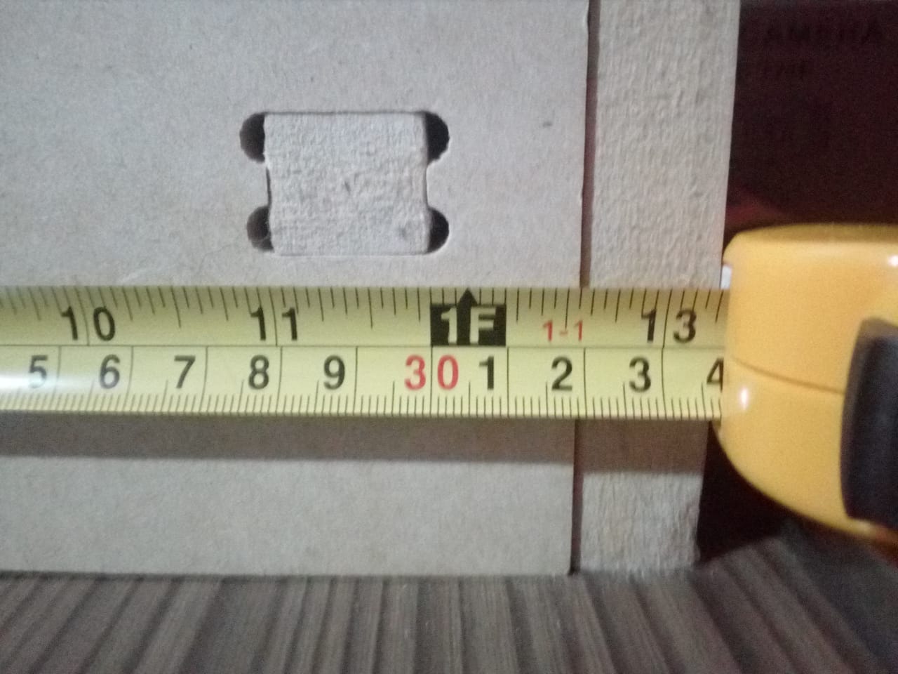
The width is 33.6 cm.
Both measures coincide with those of the design.
Definitely manufacturing based on a digital design significantly reduces errors.
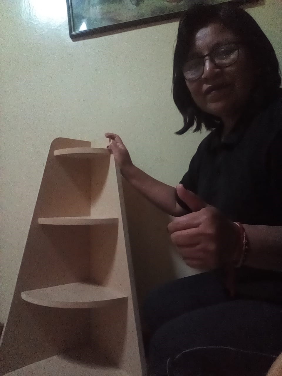
Adding some decorations to see how the corner piece looks and the truth is that it turned out very well...

Excellent!!!
Natives files
| Ord | Description | Files |
|---|---|---|
| 1 | Triangle piece | Worked Onshape |
| 2 | Corner | Worked Onshape |