11. Output devices
Working in group
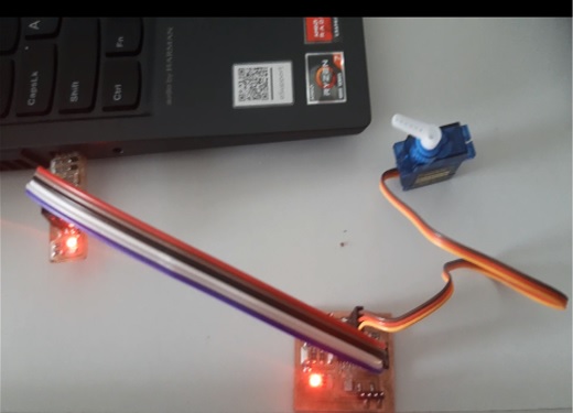
The project that is being implemented in this program consists of an automatic gel alcohol dispenser, where as an output device, which is integrated into the electronic board, previously manufactured, is an SG90 servomotor.
Description
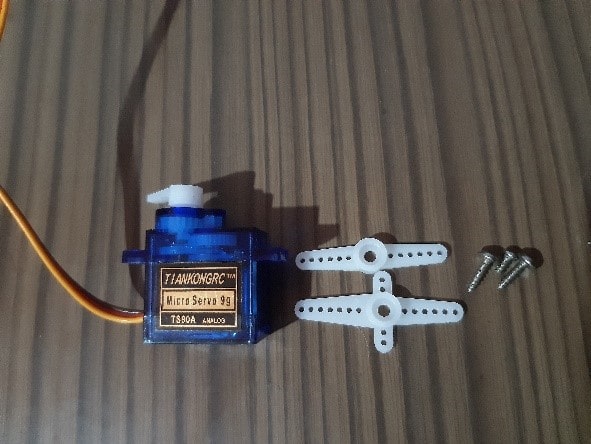
The SG90 servo motor is a small rotary actuator or motor that allows precise control in angular position, this servo motor can rotate from 0° to 180°, its operating voltage ranging from 4.8 to 6 VDC. This servo includes 3 arms and 3 screws, it has a cable of up to 25cm.
The SG90 servo has a universal “S” type connector that fits perfectly on most servo controllers.
Specifications and features
- Model: SG90
- Color blue
- Size: 22.8mm x 12.3mm x 22.5mm
- Weight: 13g
- Degrees / Maximum Rotation Angle: 0° to 180°
- Gears: Nylon
- Working temperature: -30 to +60 degrees Celsius
- 7 microseconds
- Operating voltage: 4.8VDC to 6VDC. Recommended 5VDC
- Red = Power (+)
- Brown = Power (–) or ground
- Orange= PWM signal
- Red: VCC
- Orange line: pulse input
Measuring energy consumption
Voltage measurement (V)
The worked PCB was taken and with the help of a multitester, the pointer of the negative cable (black) was located next to the ground while the positive (red) one was attached to one of the resistors.
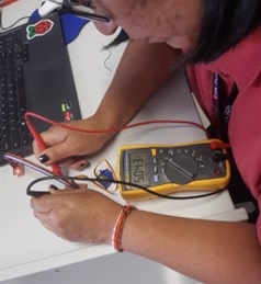
The value of the identified voltage was 5.04 volts.
Current measurement (I)
The circuit was opened to perform a series measurement. The positive lead is attached to one of the open sides while the negative is grounded.
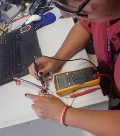
The current value was 20 mA.
Calculating the power (P)
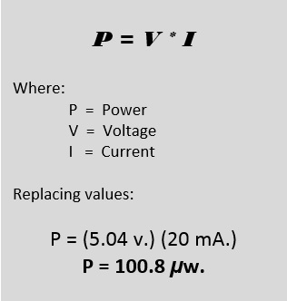
It is what the card consumes.
Working individually
Taking advantage of the device previously added to the manufactured PCB, using the ATtiny44A microcontroller; an SG90 servo motor; Applications will be developed using the Arduino Developer.
Application 01
The arm or helix of the servo motor connected to the previously manufactured plate must move 180° when the application is executed.
Before implementing the logical part, the physical part is done.
The instructions that the application must comply with are indicated below.
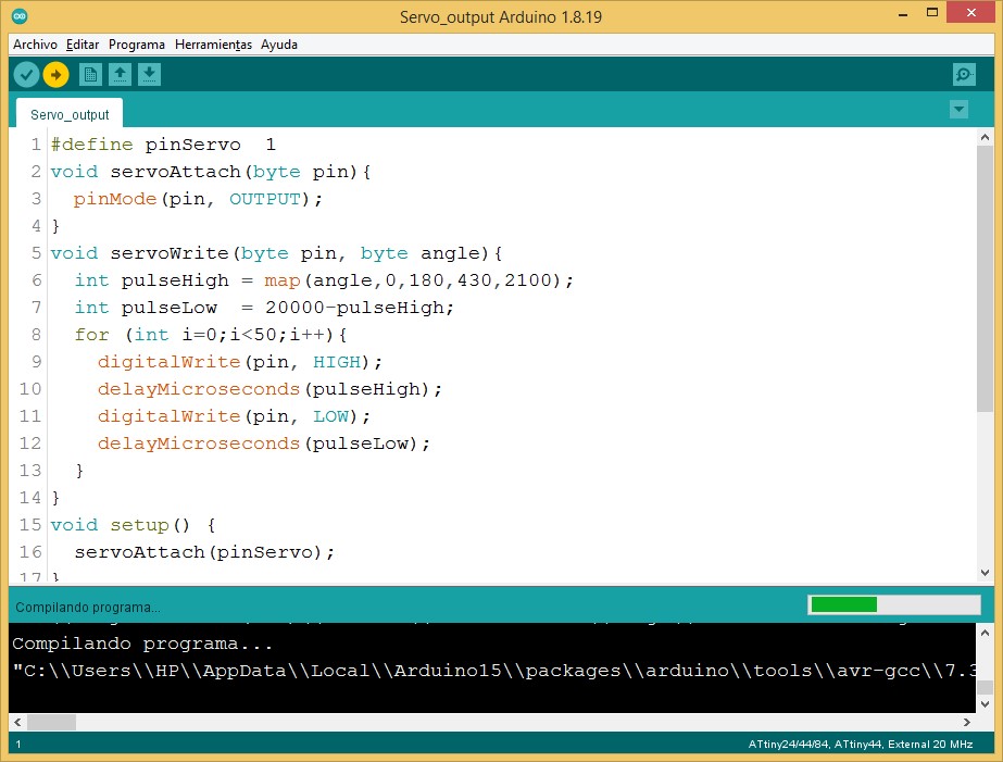
#define pinServo  1
void servoAttach(byte pin){
  pinMode(pin, OUTPUT);
}
void servoWrite(byte pin, byte angle){
  int pulseHigh = map(angle,0,180,430,2100);
  int pulseLow  = 20000-pulseHigh;
  for (int i=0;i<50;i++){
    digitalWrite(pin, HIGH);
    delayMicroseconds(pulseHigh);
    digitalWrite(pin, LOW);
    delayMicroseconds(pulseLow);
  }
}
void setup() {
  servoAttach(pinServo);
}
int pos = 0;
void loop() {
  for (pos = 0; pos <= 180; pos += 1) {
    servoWrite(pinServo, pos);
    //delay(5);
  }
  for (pos = 180; pos >= 0; pos -= 1) {
    servoWrite(pinServo, pos);
    //delay(5);
  }
}
Taking you to the coding area of the Arduino.
The physical execution can be seen in the following video:
As can be seen in the video, when the application is executed, the propeller or servomotor arm moves pulse after pulse, until reaching a 180° position. Arriving at this position, it returns to the starting position. The movement starts in a clockwise direction and the return in an anti-clockwise direction.
Application 02
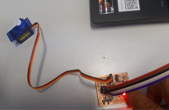
By pressing a button, the servo motor arm should translate to 90° with return.
Coding:
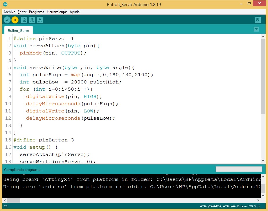
#define pinServo  1
void servoAttach(byte pin){
  pinMode(pin, OUTPUT);
}
void servoWrite(byte pin, byte angle){
  int pulseHigh = map(angle,0,180,430,2100);
  int pulseLow  = 20000-pulseHigh;
  for (int i=0;i<50;i++){
    digitalWrite(pin, HIGH);
    delayMicroseconds(pulseHigh);
    digitalWrite(pin, LOW);
    delayMicroseconds(pulseLow);
  }
}
#define pinButton 3
void setup() {
  servoAttach(pinServo);
  servoWrite(pinServo, 0);
  pinMode(pinButton, INPUT);
}
void loop() {
  if (digitalRead(pinButton)){
    servoWrite(pinServo, 90);
    delay(3000);
    servoWrite(pinServo, 0);
  }
}
In the code area.
Physical output.
In the video:
When the button or button is pressed, the servomotor arm moves 90° clockwise, then returns to its initial position. As can be seen in the following video:
Natives files
| Ord | Description | Files |
|---|---|---|
| 1 | App Servo output | Servo_output.ino |
| 2 | App Button Servo | Button_Servo.ino |