7. Electronics design
Working in group
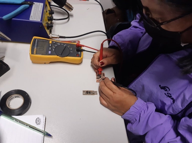
Voltage measurement (V)
The worked PCB was taken and with the help of a multitester, the pointer of the negative cable (black) was located next to the ground while the positive (red) one was attached to one of the resistors.
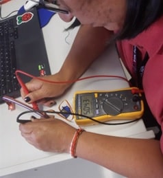
The value of the identified voltage was 5.04 volts.
Current measurement (I)
The circuit was opened to perform a series measurement. The positive lead is attached to one of the open sides while the negative is grounded.
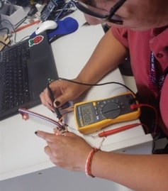
The current value was 20 mA.
Calculating the power (P)

It is what the card consumes.
Working individually
In this second block; individual work; It begins with the selection of a microcontroller, in my case, in the digital fabrication laboratory of the institute, I had an Attinny44A available to me and according to references that I have been able to find, it is a small microcontroller, with low consumption and high performance.
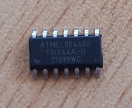
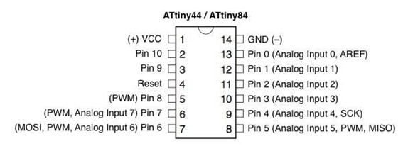
Identifying the structure of an ATtiny44A microcontroller.
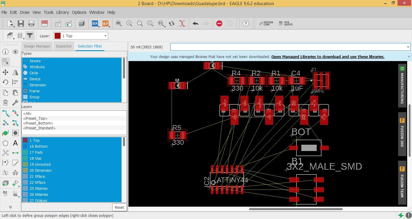
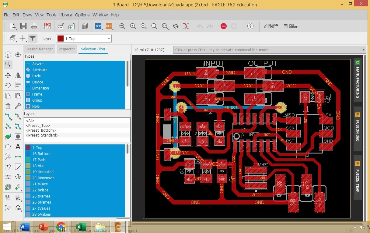
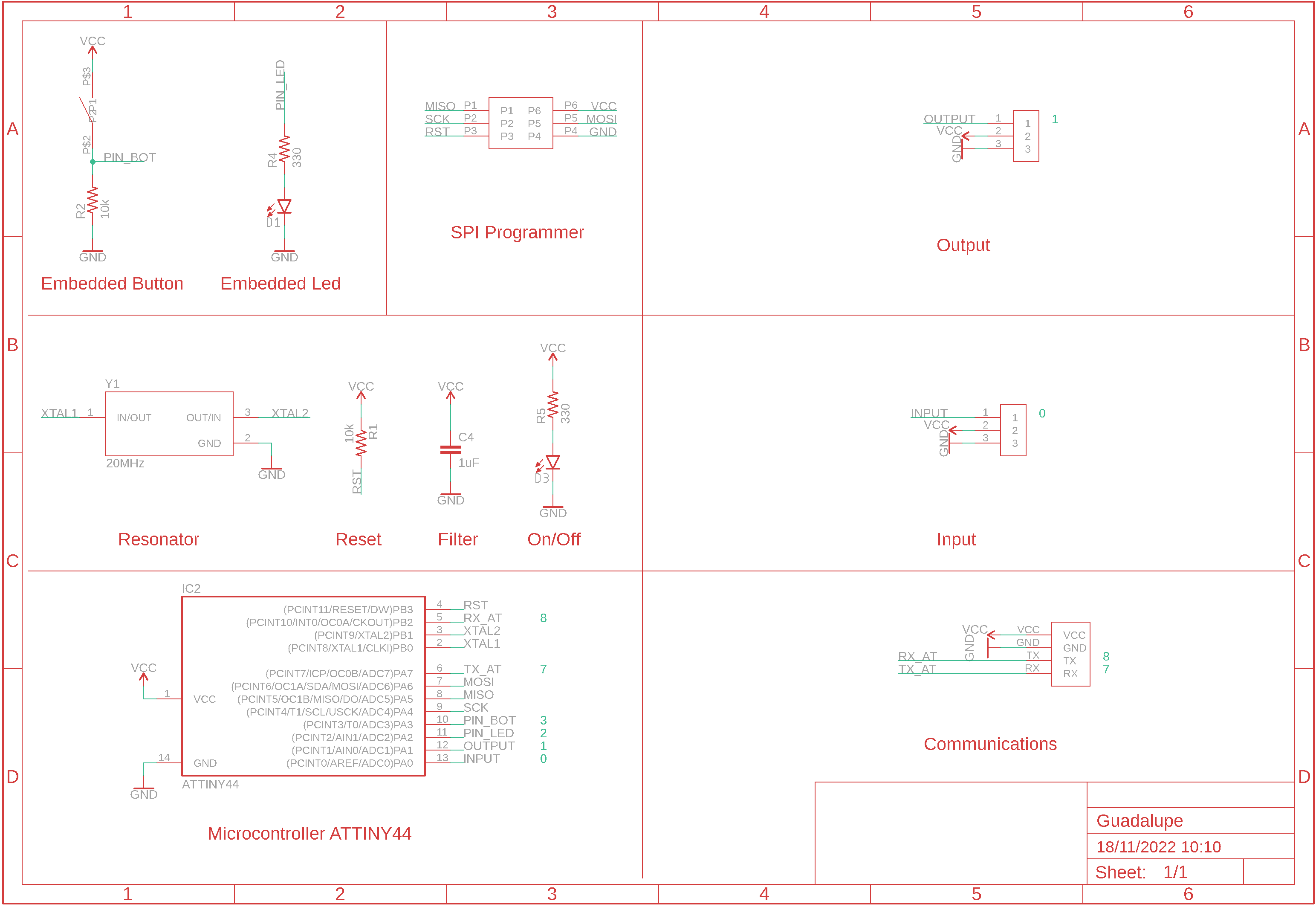
Selecting the microcontroller, I proceed to the design of the card in the Autodesk Eagle software.

Running the software, I use the interface resources of the Eagle's schematic environment to start the design of the card. Always taking the ATtiny44A microcontroller as a reference.
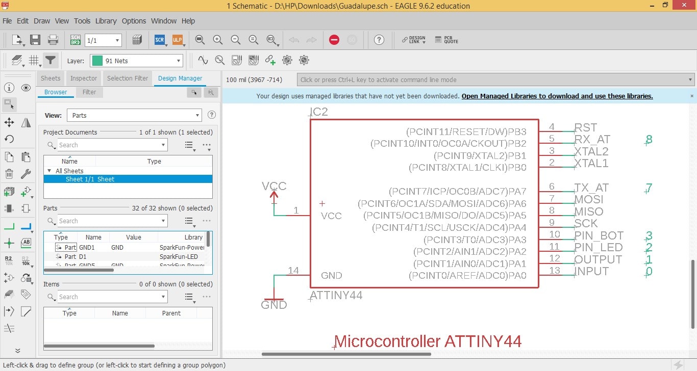
I build the design, starting by including the main components such as: microcontroller, programmer, resonator, reset, power supply and an LED.
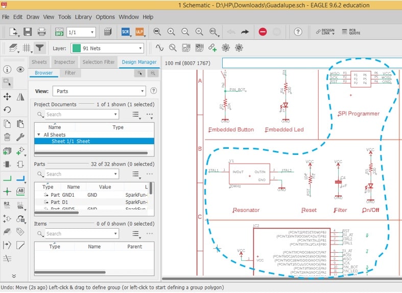
Inserting other components and making the necessary adjustments in the design.
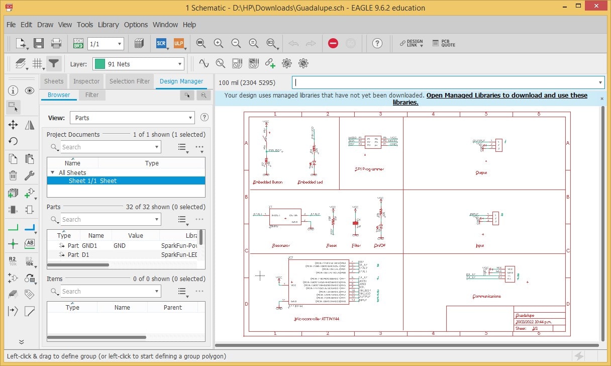
The following video shows part of the schematic design procedure.
Generating or changing to board environment:
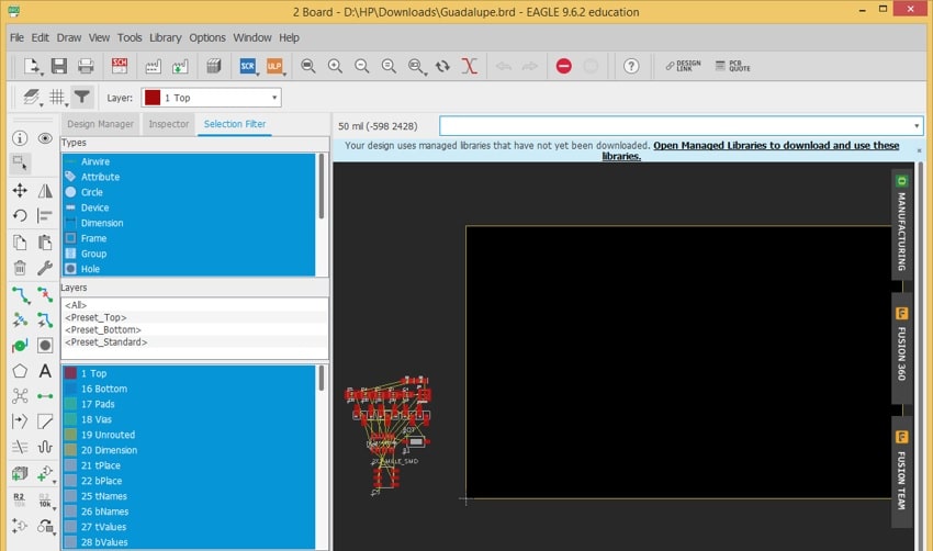
Sorting the components:
Finishing locating all the components.
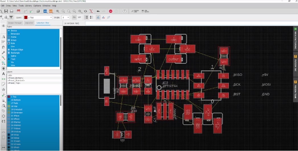
Now it only remains to make tracks or connections between them, in a coherent and optimal way.
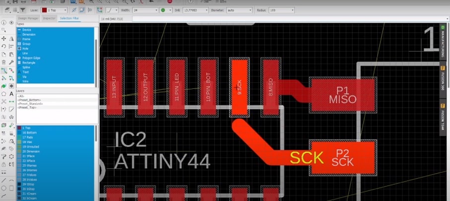
To avoid crossing some connections, two bridges had to be built.
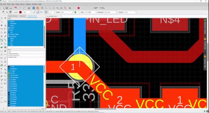
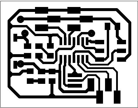
Labels were added and some PCB layout tweaks were made, finally ending up like this:
To generate the folders and files necessary to perform the cut on the milling machine, we click on CAM processor.
Click on Process Job and select the storage folder, accept.
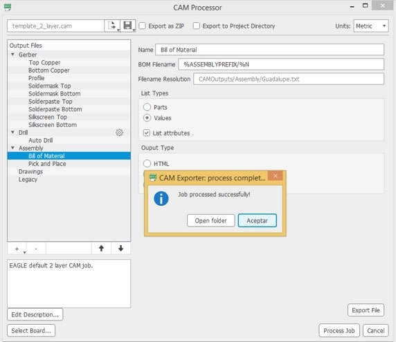
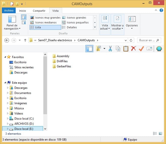
And we get what is generated.
Now we run the FlatCAM software.
And I load one of the files generated earlier on the Eagle into the gerber pool; cooper_top.
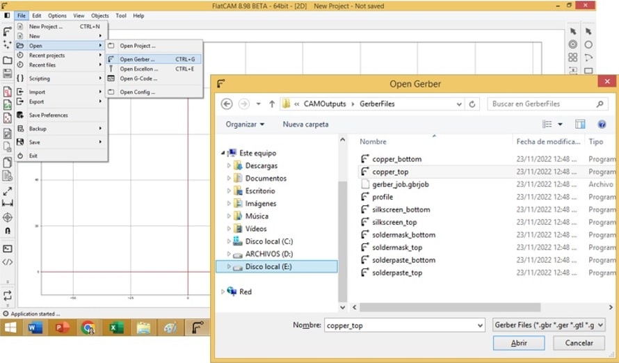
And it is possible to load the previously worked design.
It corresponds to do the routing now and then cut it. For this, first we will generate the routes that will isolate the object we want.
First, the geometry is generated, taking into account the calculated diameter of the cutter (0.1536), in addition to the over-assembly of the passes (90%) and the type of milling.
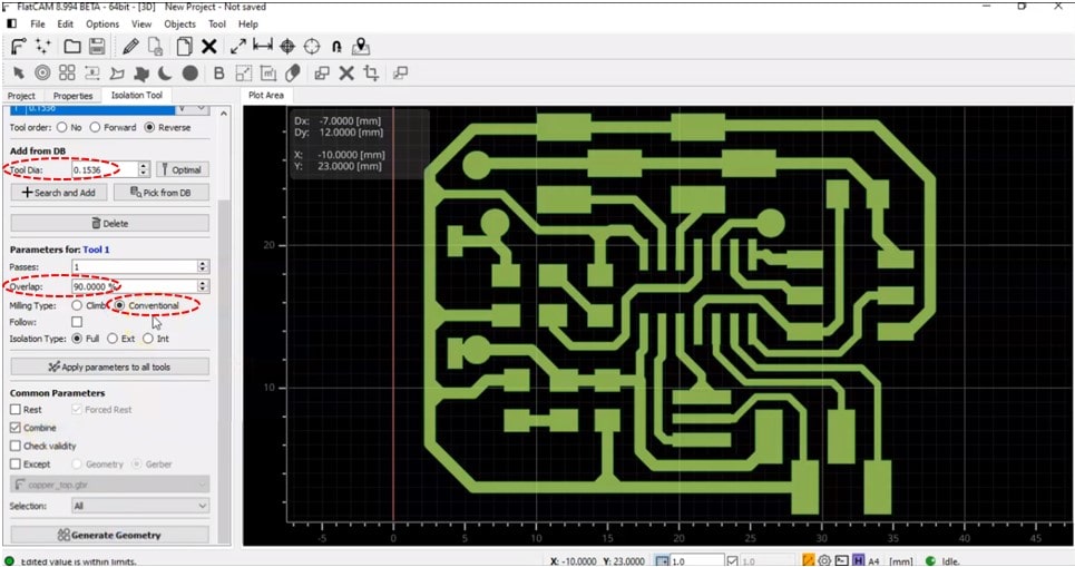
And finally I select the Generate Geometry button, to generate the geometry, the same one that can be seen in the red edges of the object.
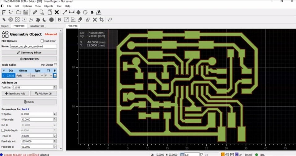
For the generation of the Gcode, which is the language that the machine understands to make the route, parameters such as angle, tool diameter, depth and speed must be configured.
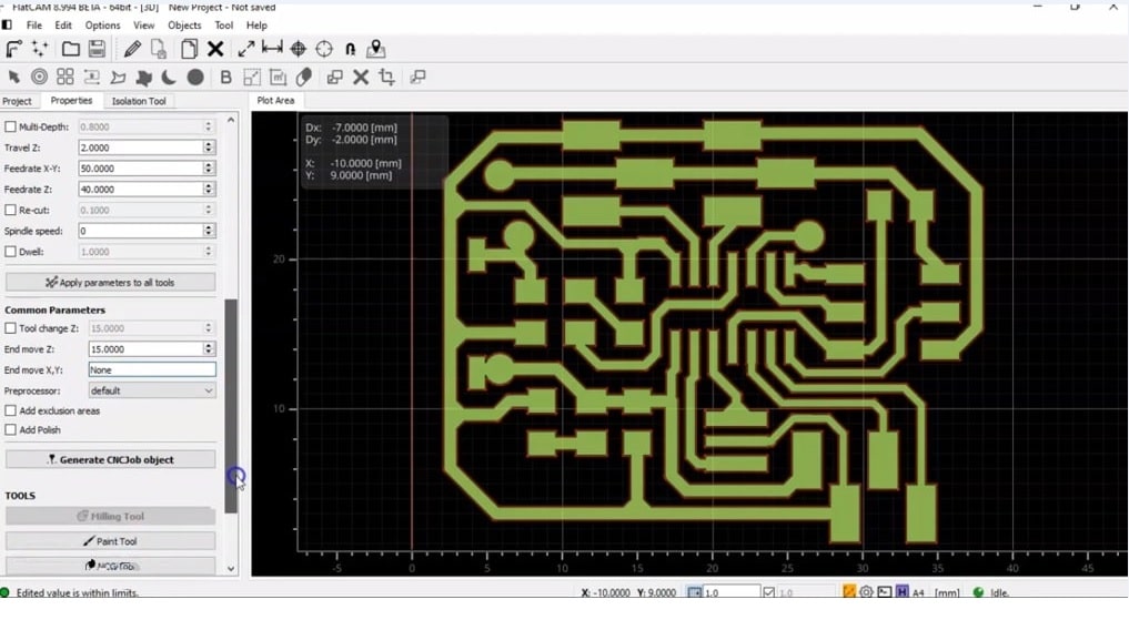
Clicking on Generate CNCJob object, it is possible to generate the object to be cut, in blue.
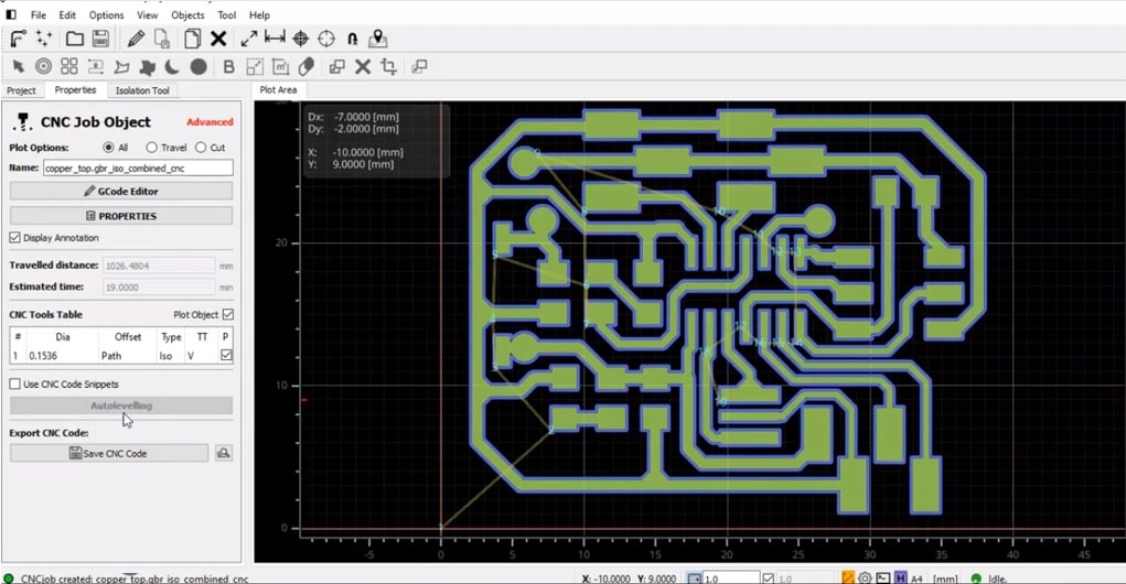
By selecting Save CNC Code, I save the file copper_top.gbr_iso_combined_cnc.nc
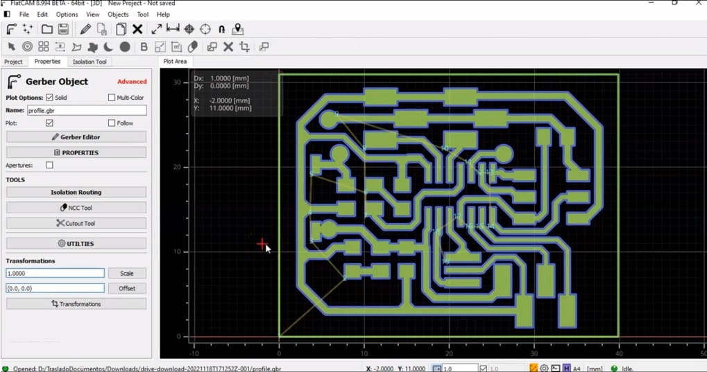
I load the profile.gbr file to customize the perimeter.
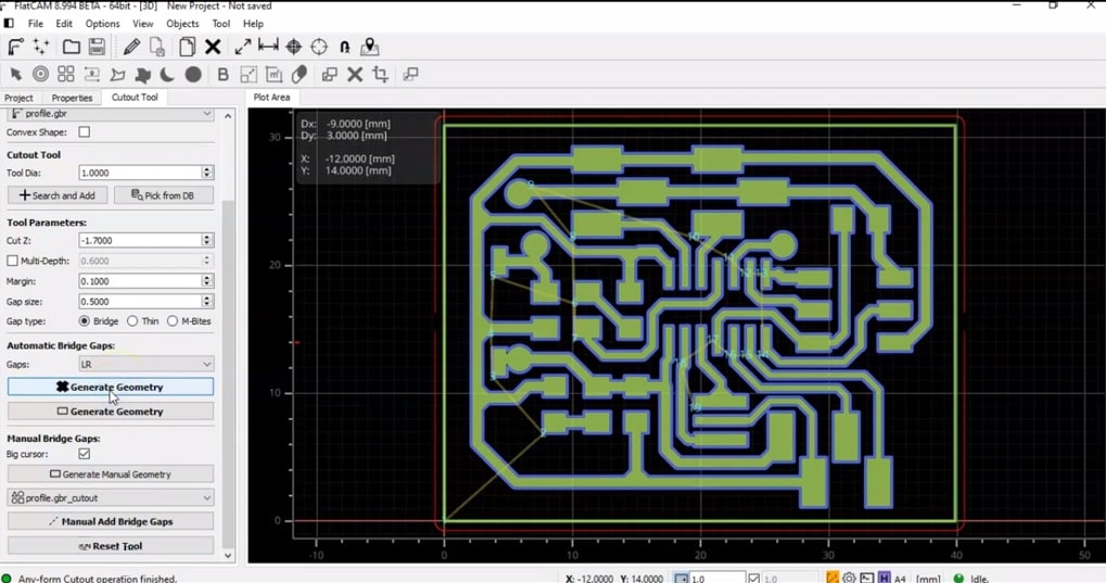
In the Cutout Tool, I specify the cutting parameters such as total cut, diameter and margin to then generate the geometry (Red box).
To generate the cut language, in Project I select the generated file profile.gbr.cutout and configure the speeds with which the tool will travel. In Feedrate X – Y, the speed is lowered to 60.
Finally, click on Generate CNCJob object. A thick blue border is observed.
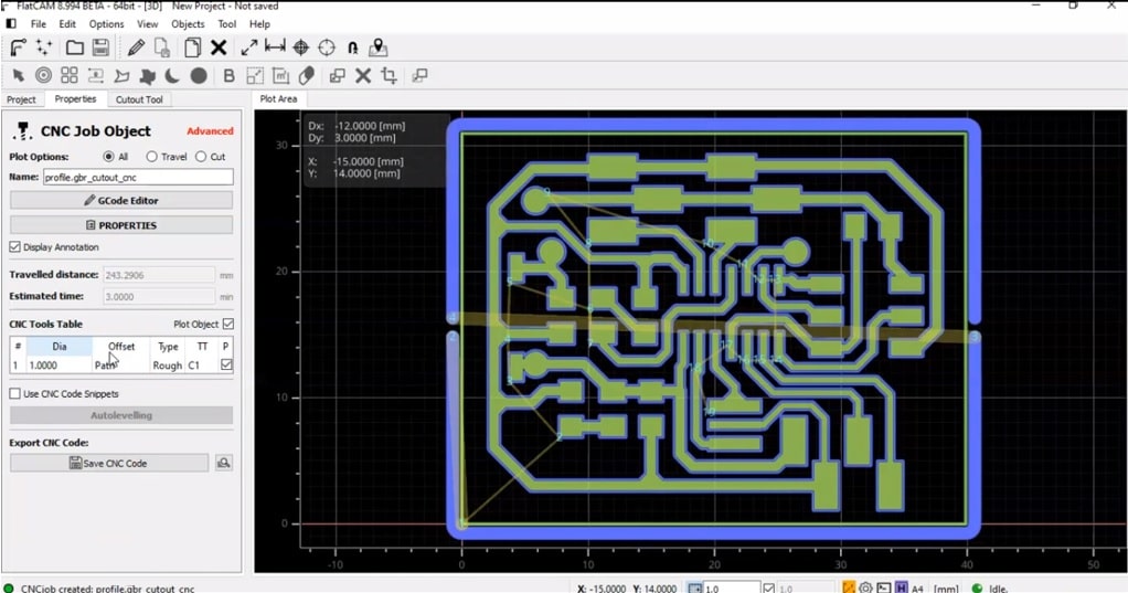
In the same way as in the previous case, we proceed to save the file profile.gbr.cutout.cnc.cn
Ready!!!, now to cut.
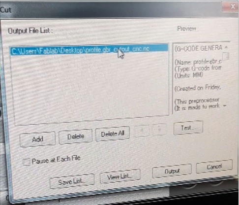
The milling is going to be done on the Monofab mini milling machine, so I proceed to turn it on and load the file copper_top.gbr_iso_combined_cnc.nc
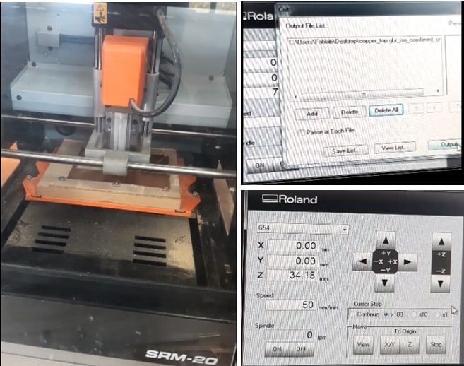
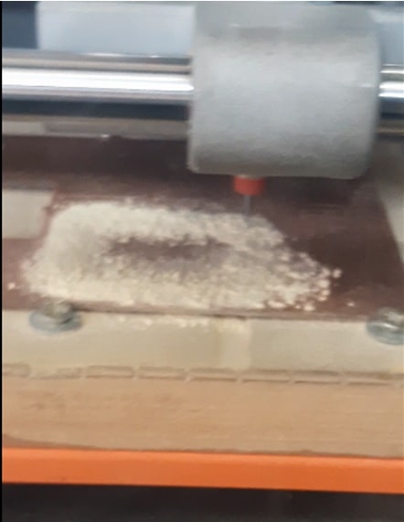
And it begins to grind.
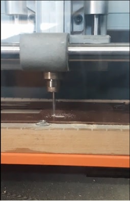
Finished with milling.
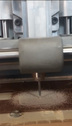
Part of the milling procedure.
Cleaning up the leftovers.
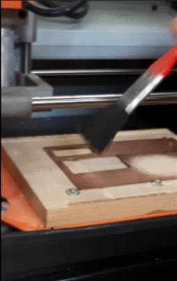
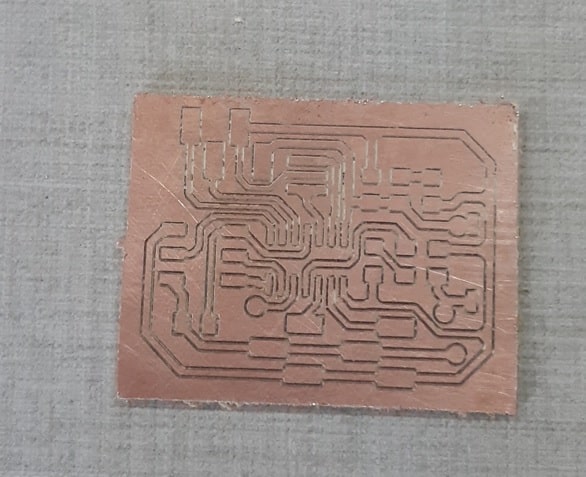
Having a clean etched plate display.
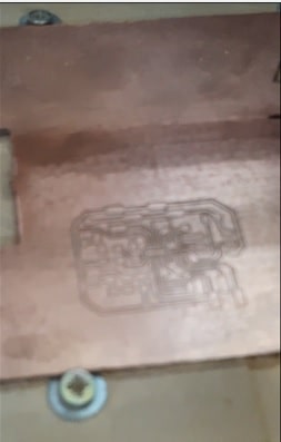
Fairly good!!!
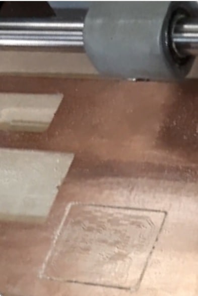
After the mill has been changed, because the borse is now to be cut, the file profile.gbr.cutout.cnc.cn is loaded and the milling procedure is repeated.
After cleaning the residue, the plate is as shown in the following image:
Removing the cut plate.
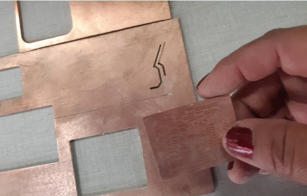
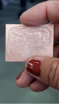
View of the finished milling plate.
With the plate in my hands.
Now to weld.
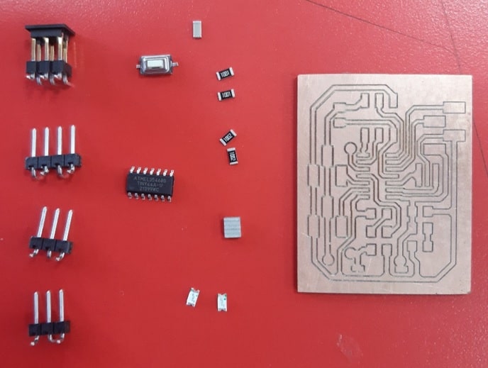
First we need to know the necessary components to start with the soldering. We open the generated text file to know the components.
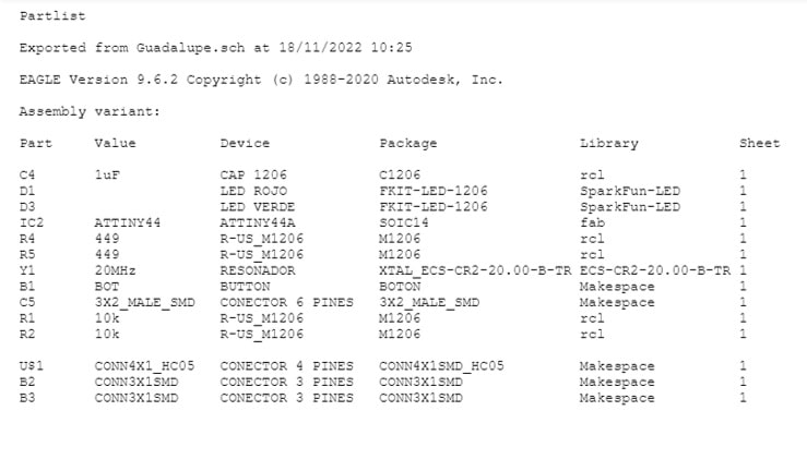
Preparing the components.
In the middle of the welding process.
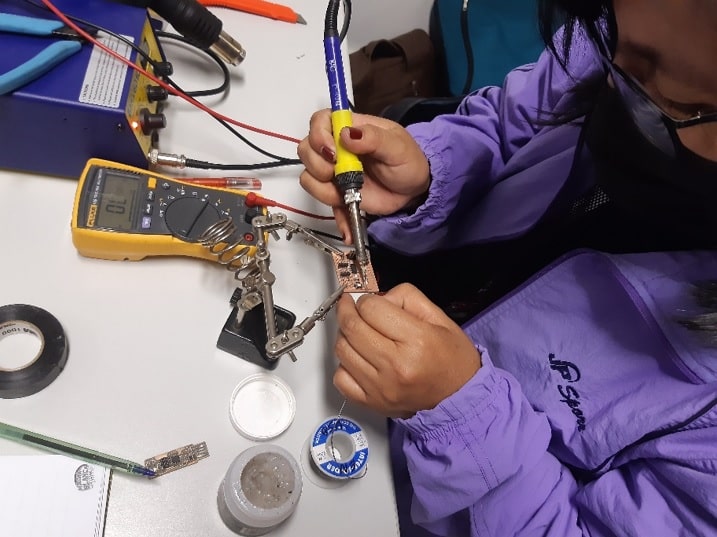
Completed weld.
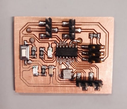
Checking that the welding work has been done correctly.
Everything is OK.
Starting to program
Before starting to apply programming instructions, I recover the previously worked FabISP and connect it to the newly manufactured PCB, using ISP cables.
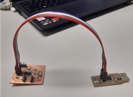
Making contact with my laptop.
All ready to start programming.
The Arduino software is the chosen one to program.

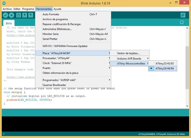
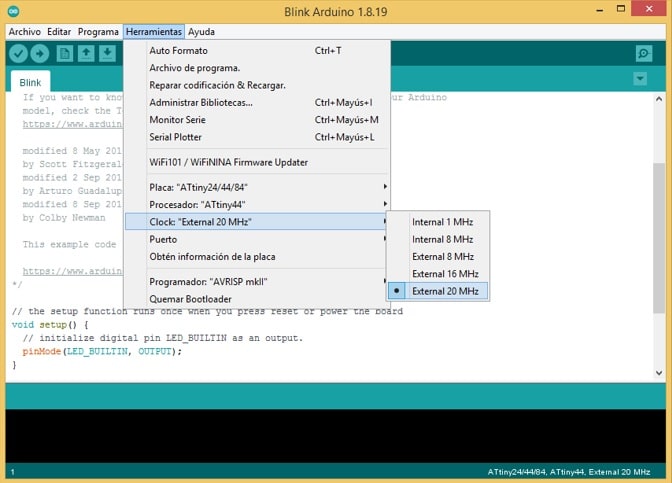
Locating ourselves in the Arduino IDE, we configure before starting to develop applications.
I select Tools from the menu bar/Board “[Name__board]>”/ATtiny Microcontrollers/ATtiny24/44/84
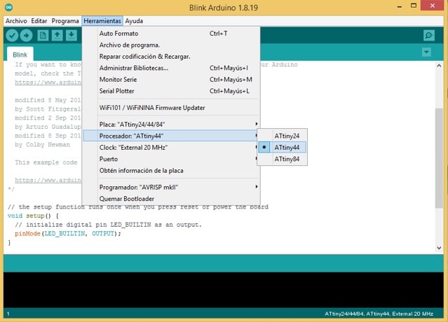
Next step is to specify the processor, for that select Tools/Processor “ATtiny24”/ATtiny44.
In addition, it must be indicated which crystal oscillator is going to work: Tools/Clock “[oscillator_name]”/External 20 Mhz.
And finally, I select the programmer according to the hardware that is available. Tools/Developer “[developer_name]”/USBtinyISP
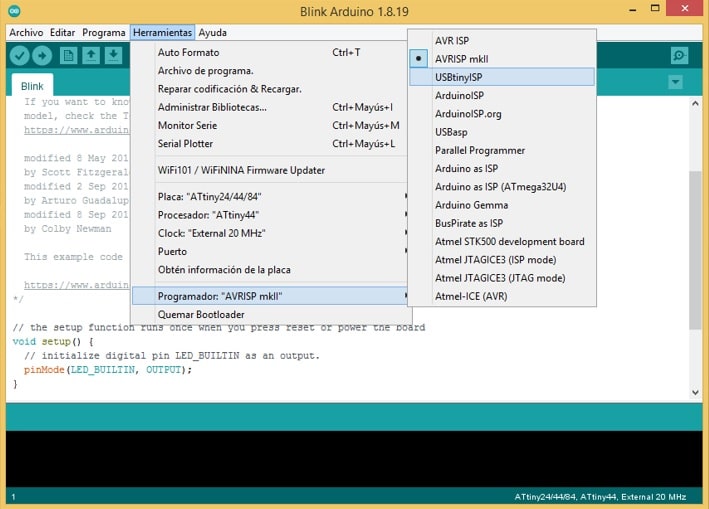
Ready, we start developing applications.
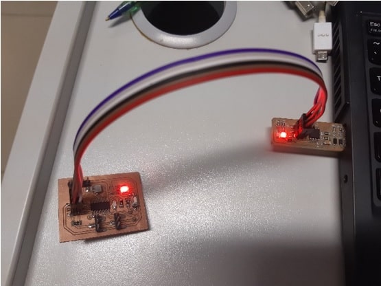
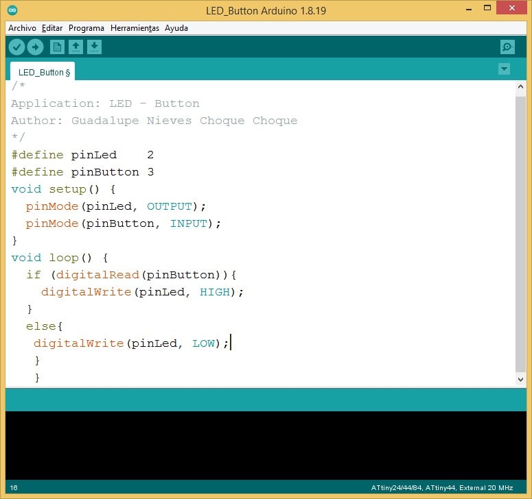
Through the following application it is intended that, when a button is pressed, an LED lights up.
Solution: In the coding area we write the following lines of instructions:
/*
Application: LED - Button
Author: Guadalupe Nieves Choque Choque
*/
#define pinLed    2
#define pinButton 3
void setup() {
  pinMode(pinLed, OUTPUT);
  pinMode(pinButton, INPUT);
}
void loop() {
  if (digitalRead(pinButton)){
    digitalWrite(pinLed, HIGH);
  }
  else{
    digitalWrite(pinLed, LOW);
  }
}
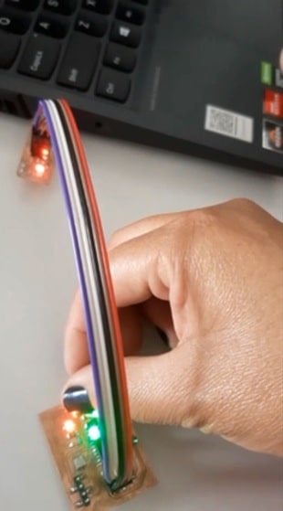
Observing the results physically.
Additional
Practicing with the Proteus.
For the development of this part of the work an electronic design automation software is needed. Proteus 8.10 has been used for this purpose.

This software has a properly structured interface, which allows the design to be carried out in a simple and fast way.
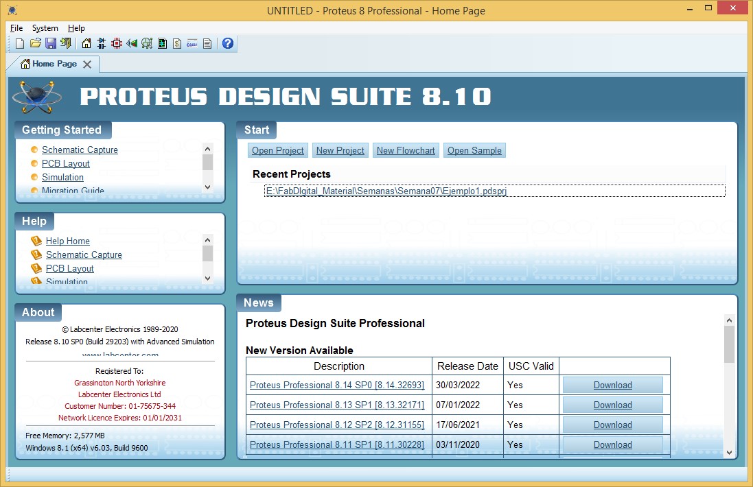
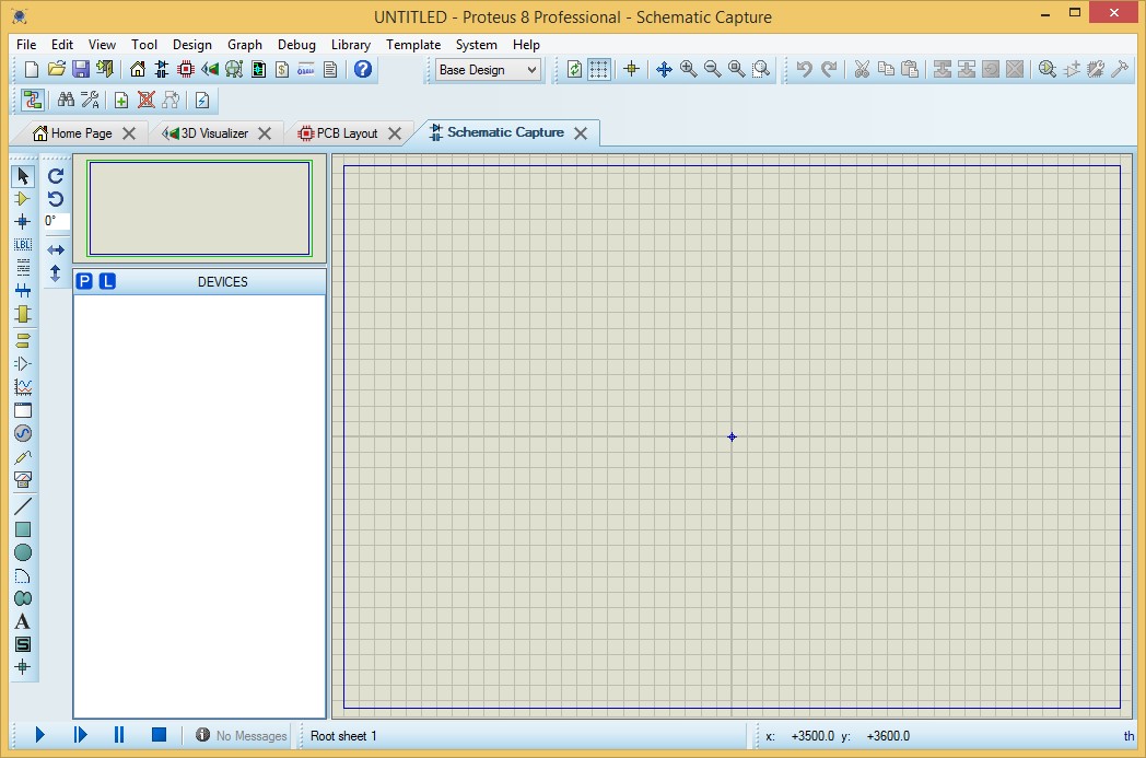
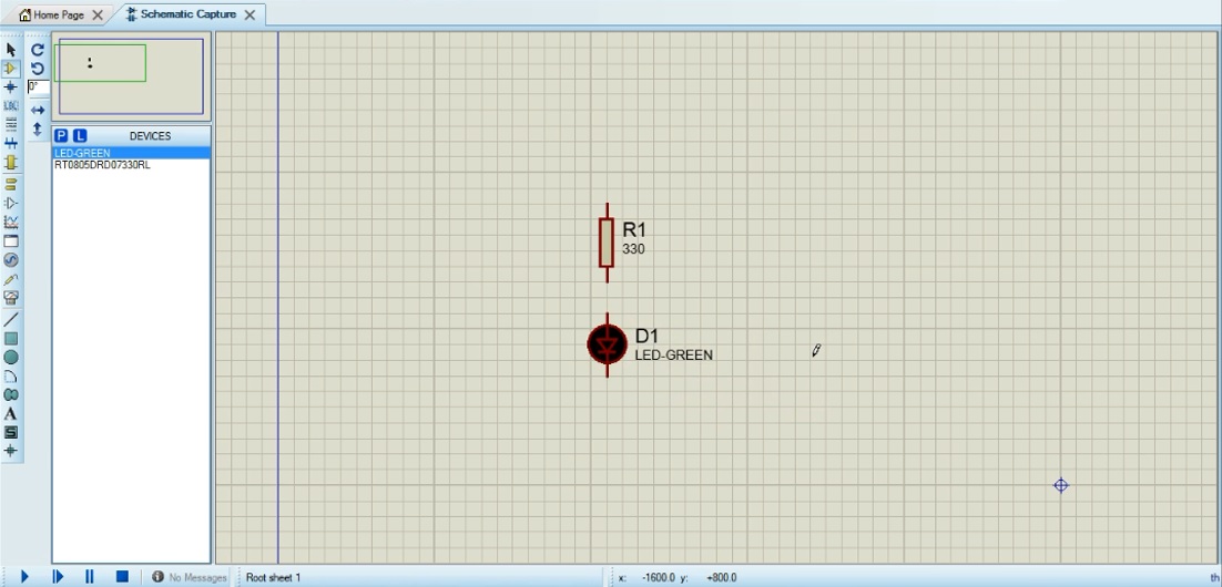
By selecting the schematic capture button on the toolbar we can enter the design window:
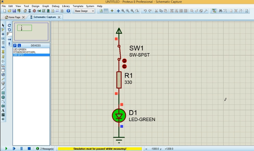
According to the case, we are going to turn on and off an LED, so we are going to proceed to insert a resistor and an LED. Then we proceed with the design:
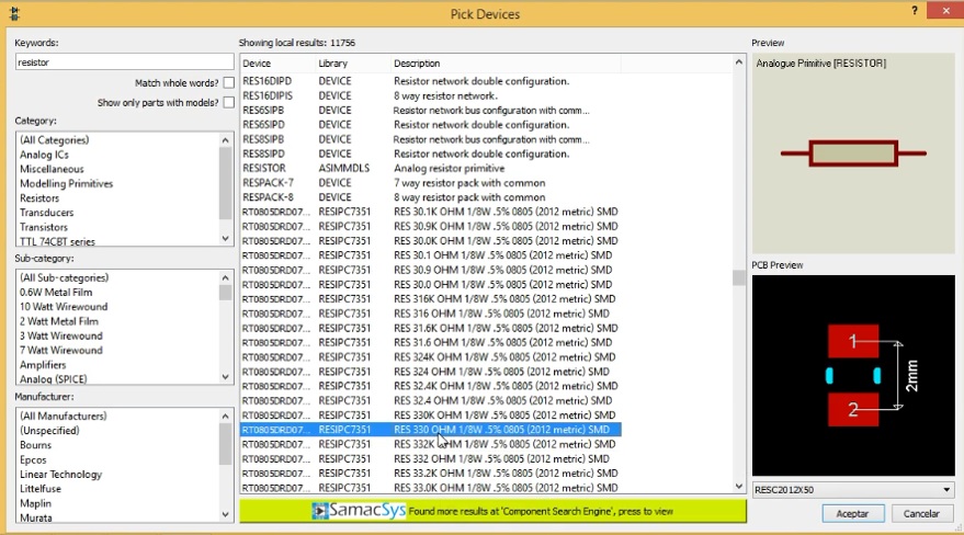
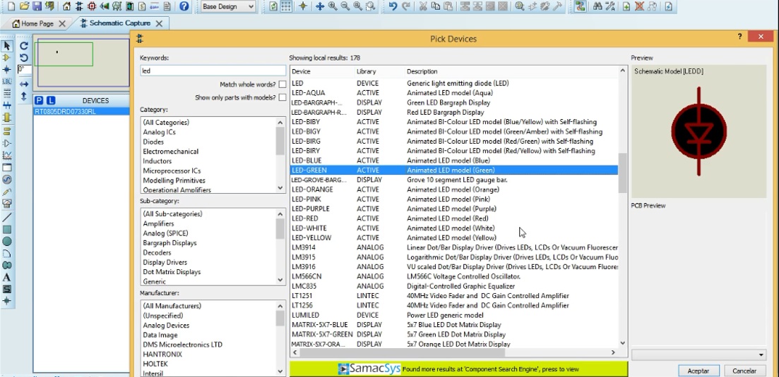
Both objects are inserted in the design area.
By adding terminals, the design will be ready.
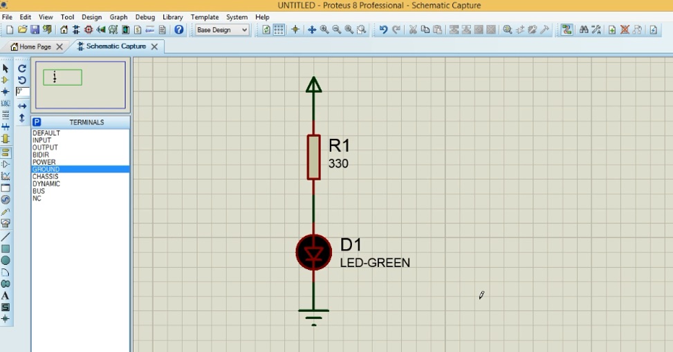
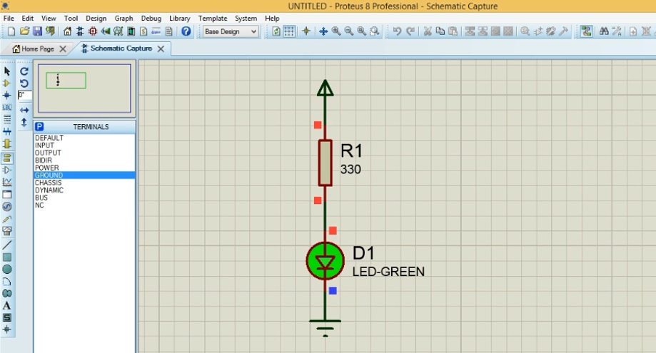
Simulating the execution, it can be seen:
Now with the purpose of executing with a physical pushbutton a switch is added.
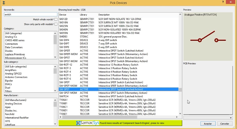
When executing, a change of colors can be seen.
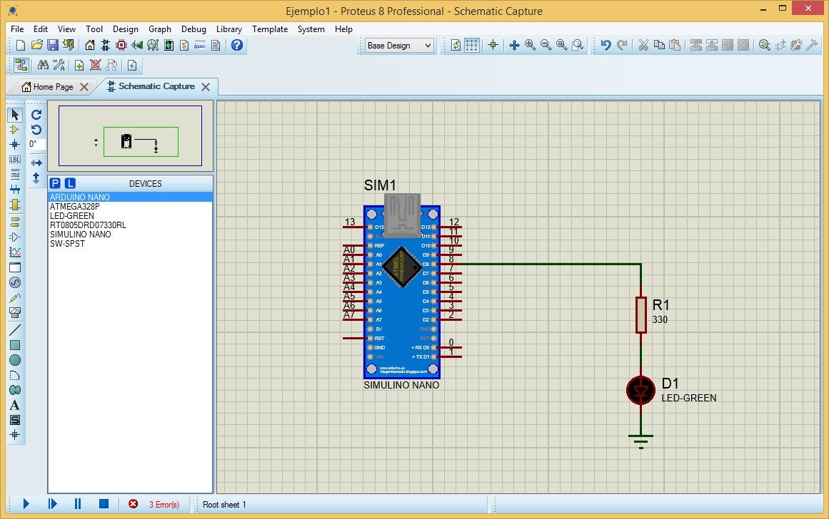
Adding a microcontroller.
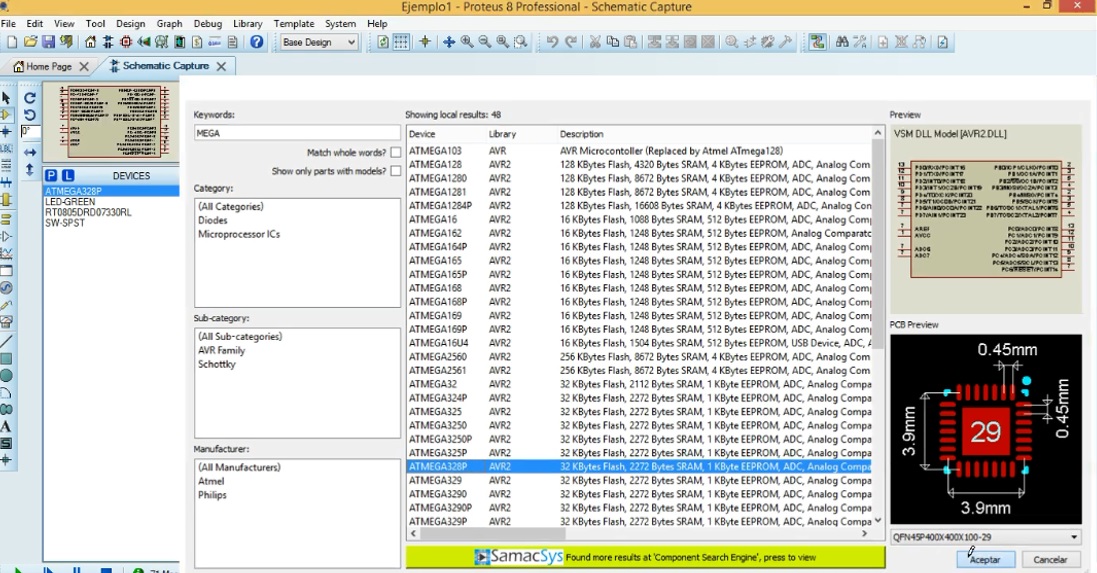
Inserting it we have:
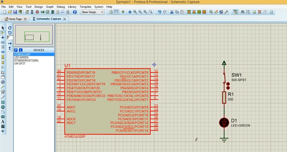
Making the necessary connections, it remains:
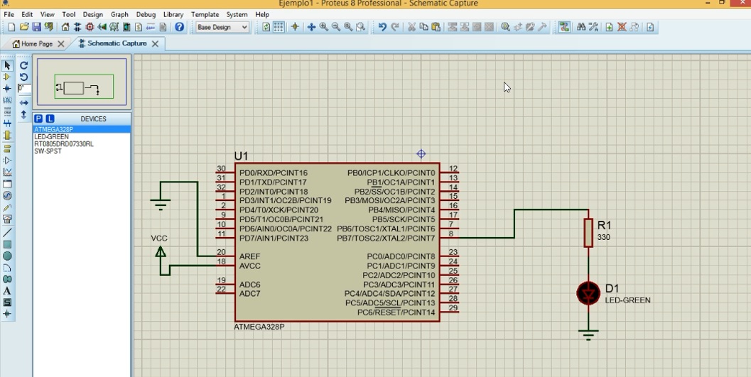
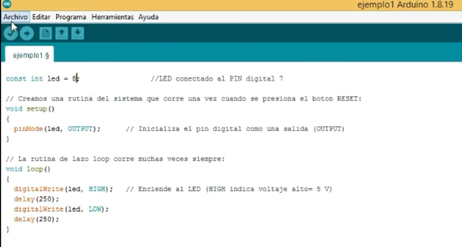
Now for the purpose of programming the microcontroller we use the Arduino programming language.
We proceed to give the necessary instructions in the code area:
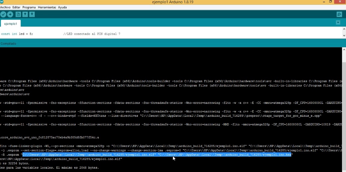
Performing the compilation and looking for the file with hex extension to copy it.
Inserting the Simulino Nano,
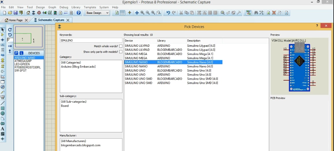
Paste the file with hex extension in Program file,
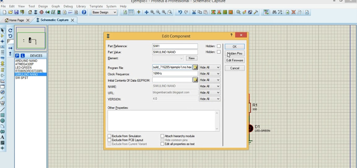
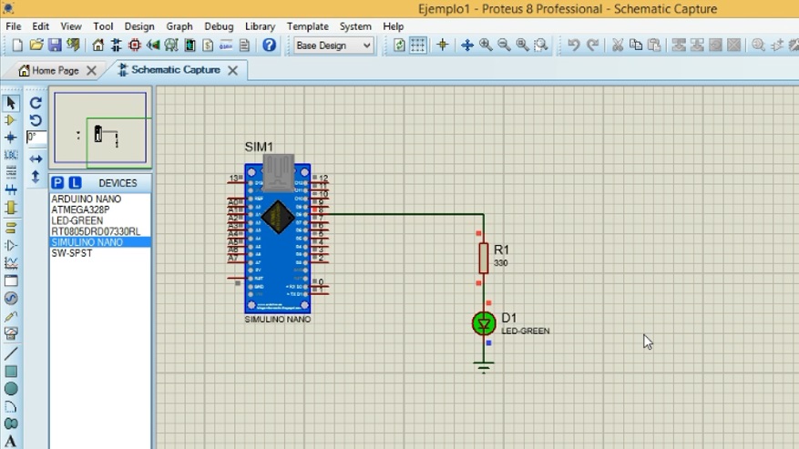
You have:
Executing it is observed:
Natives files
| Ord | Description | Files |
|---|---|---|
| 1 | Eagle Schematic | Proy_Eagle_Board.brd |
| 2 | Eagle Board | Proy_Eagle_Schem.sch |
| 3 | Image Board | Proy_Image_Board.png |
| 4 | Image Schematic | Proy_Image_Schem.png |
| 5 | App | App_LED_Button.ino |