4. Computer controlled cutting
Working in group
Working individually
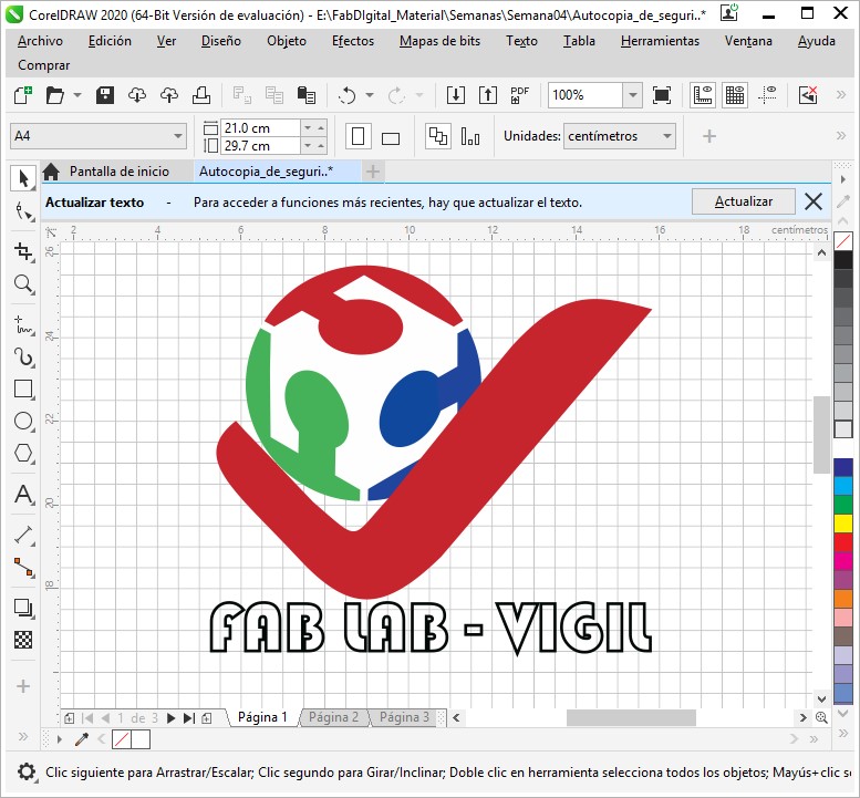
I designed a proposal for a logo, linking digital fabrication with the Vigil Institute, to later request the service of having it cut using a laser on vinyl material.
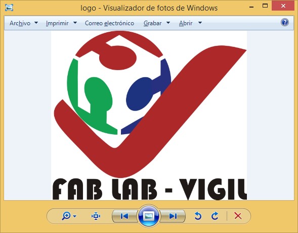
I worked on the logo design in Corel Draw, finally coming up with the following presentation:
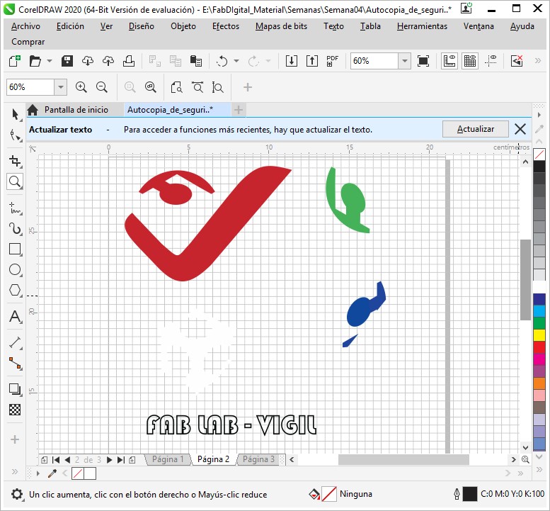
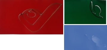
Then I separated the parts of the drawing by colors, leaving it ready for cutting.
The following video summarizes what was worked on in Corel Draw:
As the IES "Francisco de Paula Gonzáles Vigil" of Tacna, does not yet have the necessary tools to execute a laser cut and in order to see results in advance, the services of a laser cutting shop were requested, to make the cut. in vinyl material, it is recommended that the colors of the design be respected. And so it was, reaching me the final product.
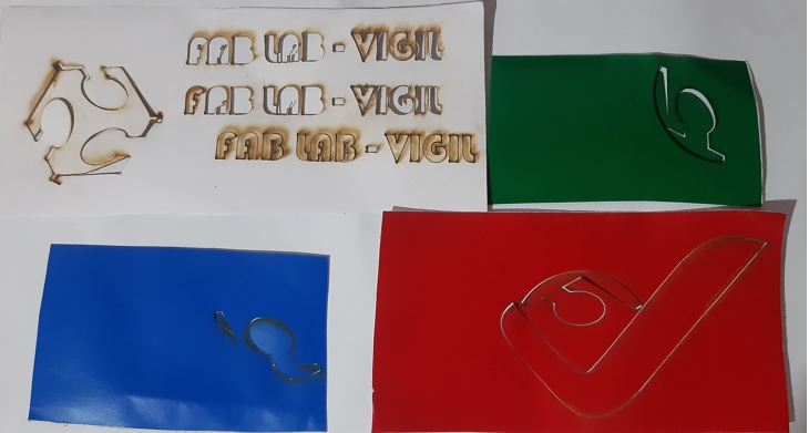
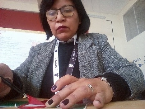
The only thing I did was separate the cut from the rest of the material:
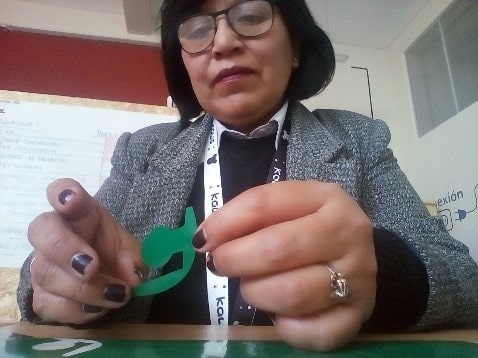
And then assemble it, according to the design drawn up earlier.
Finally leaving the logo in vinyl material, like this:
The commissioned job was to make the cut on a vinyl cutter and not a laser cutter, I had to do the job again. The good thing is that since we already have a digital manufacturing laboratory at the institute and we can have the equipment since 06/16/2022, I proceeded to develop my commissioned work at the FAB ACADEMY.
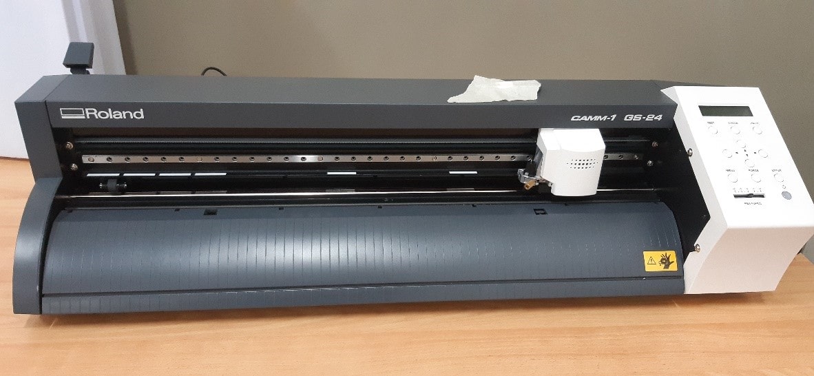
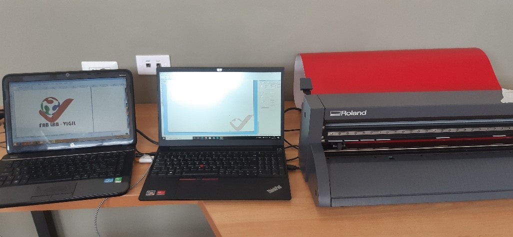
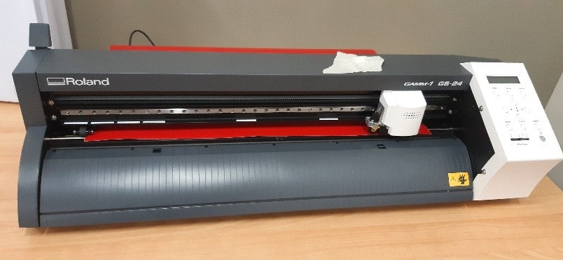
In the institute's laboratory there is a Roland CAMM-1 GS-24 tabletop vinyl cutter.
The software with which this equipment is operated is CutStudio, which, apart from ordering and configuring the cut of a certain job, allows the elaboration of designs.
In this case I will work with the design of the FAB LAB VIGIL Logo, previously made in Corel Draw. I will export the file as a JPG type so that it can be recognized by CutStudio.
Before exporting it, I will change the font color, from white to black, since the background color is white in the place where you want to place the logo. It should be noted that the color is purely for reference, it is only to have an idea of the color of the material that is going to be cut. For the moment of cutting, only the outline of the object is of interest.
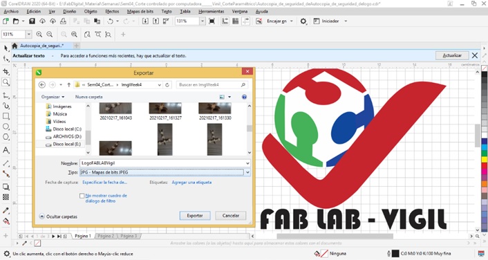
File created in JPG:
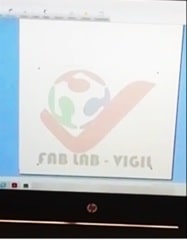
Now proceed to import the JPG file into CutStudio. There was no problem.
If you want to print everything in a single color, simply customize the cut and order it, but the idea is to obtain a product as it appears in the design, that is to say in color, so it is convenient, being in Corel Draw, to separate design objects by colors and import them in JPG. This has already been done before where the 05 files contain:

Each of the files are imported into CutStudio at different times.
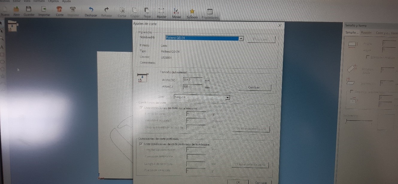
Once the file is open in CutStudio, we proceed to make the design adjustments such as size, position and format.
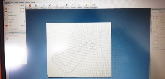
Finally, its profiling is obtained. It is based on this that the cut is made.
The Overlay Cut option greatly influences the quality of the material cut.
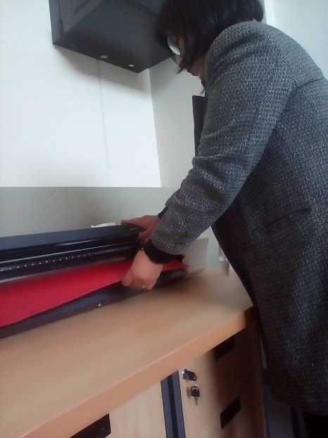
Before ordering the cut I must make sure that the computer is connected to the cutter, proceed to turn it on, load and prepare the vinyl.
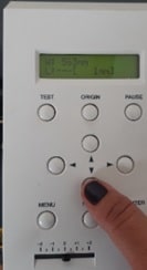
When everything is ready, the cut is ordered, selecting the Cut option.
This is how vinyl cutting worked.
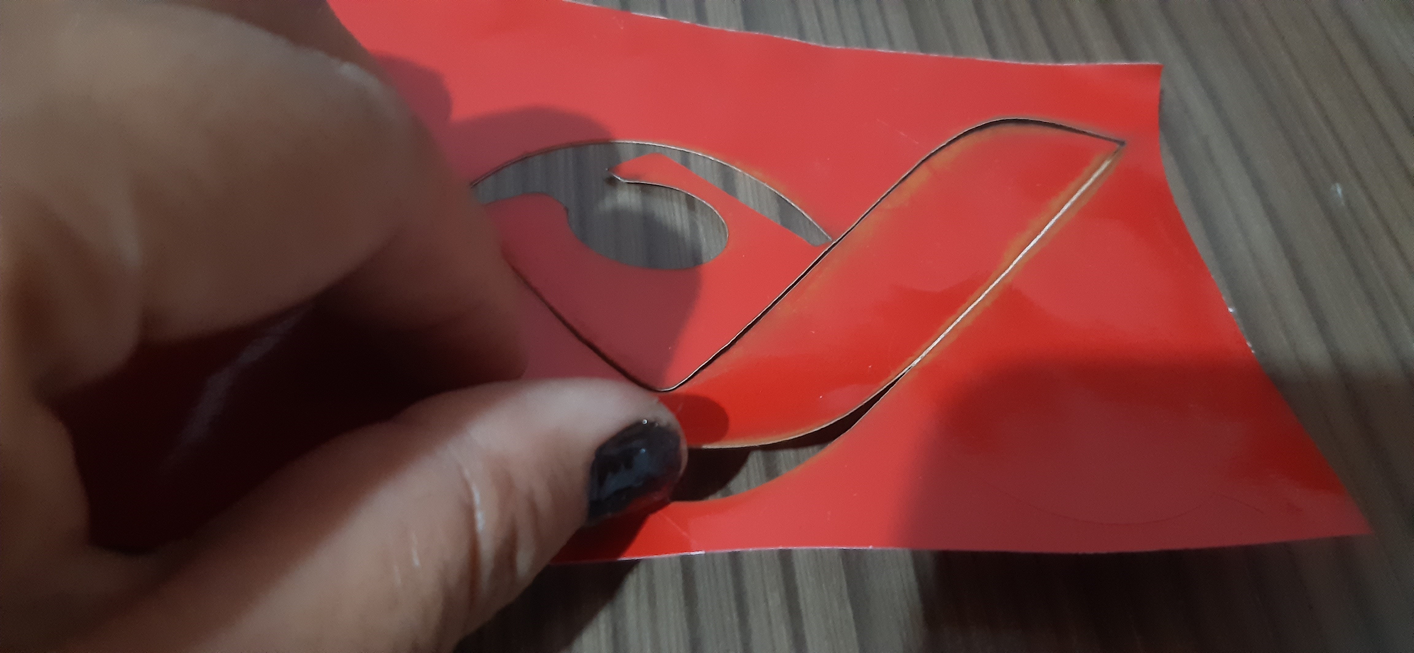
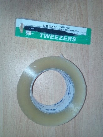
Once the vinyl was cut, the pieces were separated from the adhesive part. To do this, a clamp and a packing tape were used.
Here are the vinyl cut pieces. The white piece was skipped for the same reason the font color was changed.
With the help of a clamp, the cut pieces were removed and the leftovers were discarded.
I had to be very careful when removing the pieces of tape so as not to mess up any of the parts.
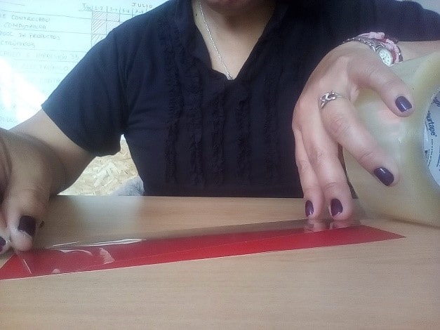
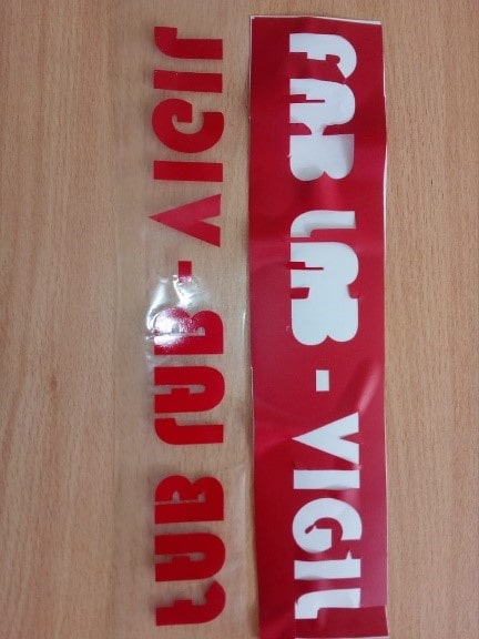
The procedure to remove the letters was different from that of the pieces of the logo. To maintain the alignment of the letters, a packing tape was used, placing it on the front of the letters and putting some pressure on each of them and then removing it very slowly, in such a way that the letters were suspended on the tape. of packing.
And indeed the letters were stuck on the packing tape.
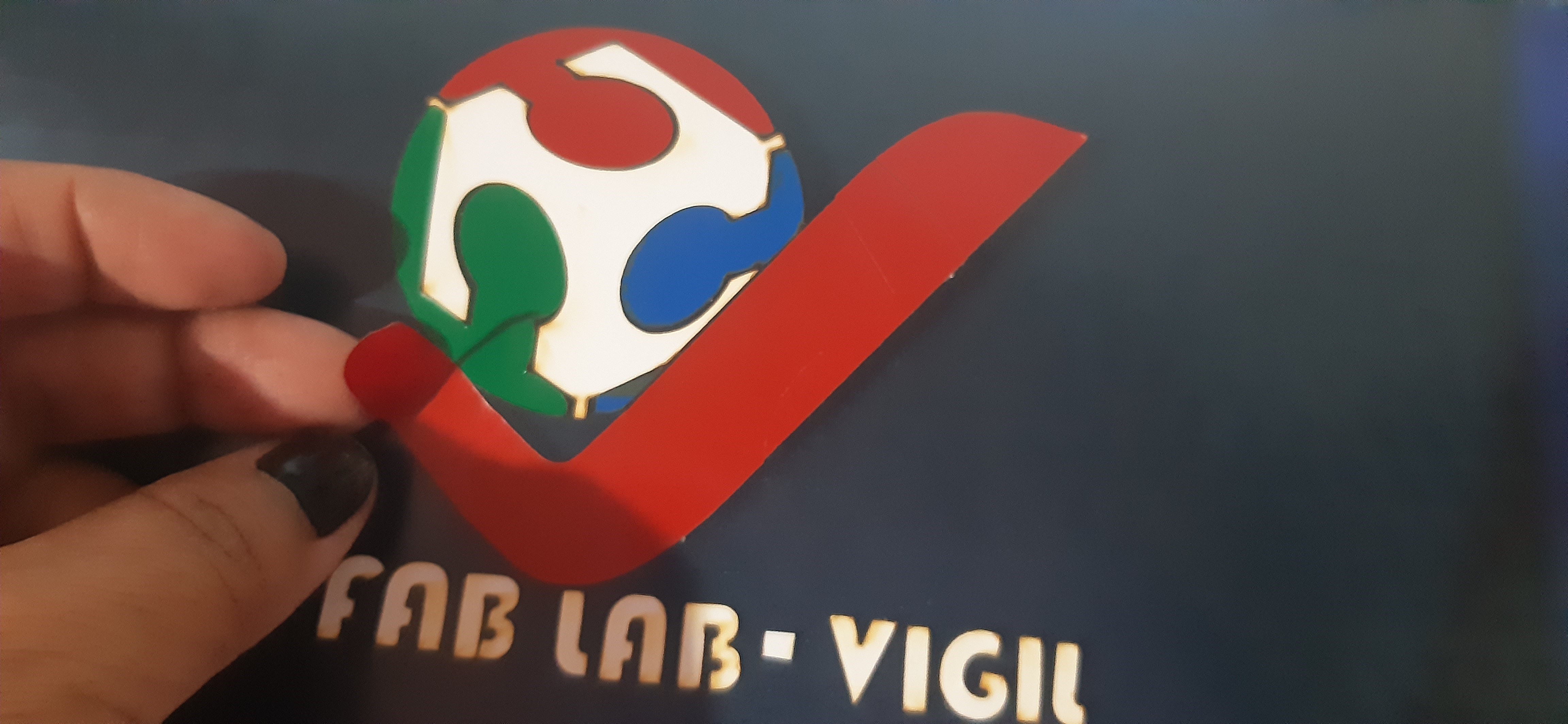
AAfter having placed the pieces of the logo on the selected display area, which is nothing less than the upper right part of the acrylic whiteboard of the digital fabrication laboratory, he took the letters held by the packing tape towards the whiteboard. Placing them aligned and pressing on each of the letters very slowly and gently, the packing tape was removed, leaving the letters stuck to the board.

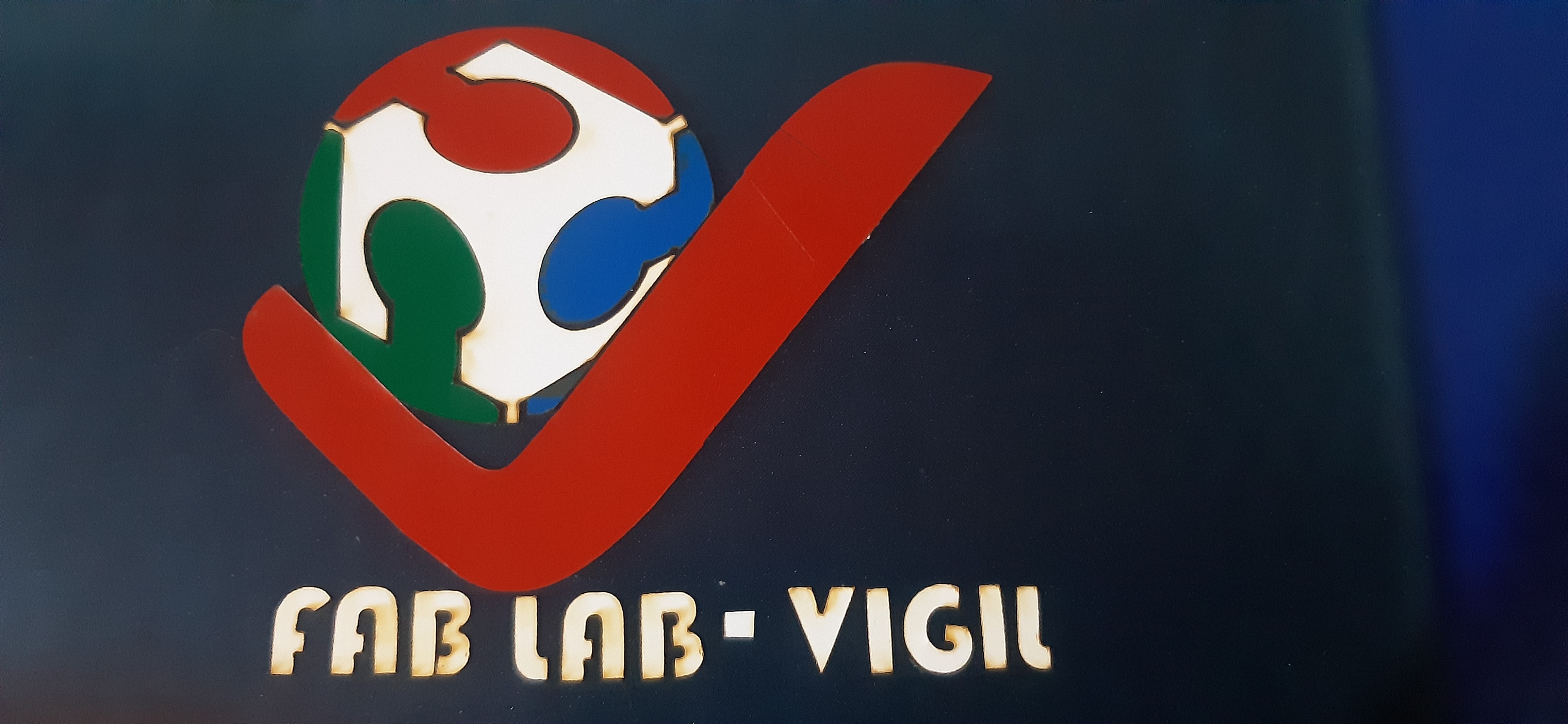
Finally, the logo was like this:
And in a total view of the board the logo is displayed like this:
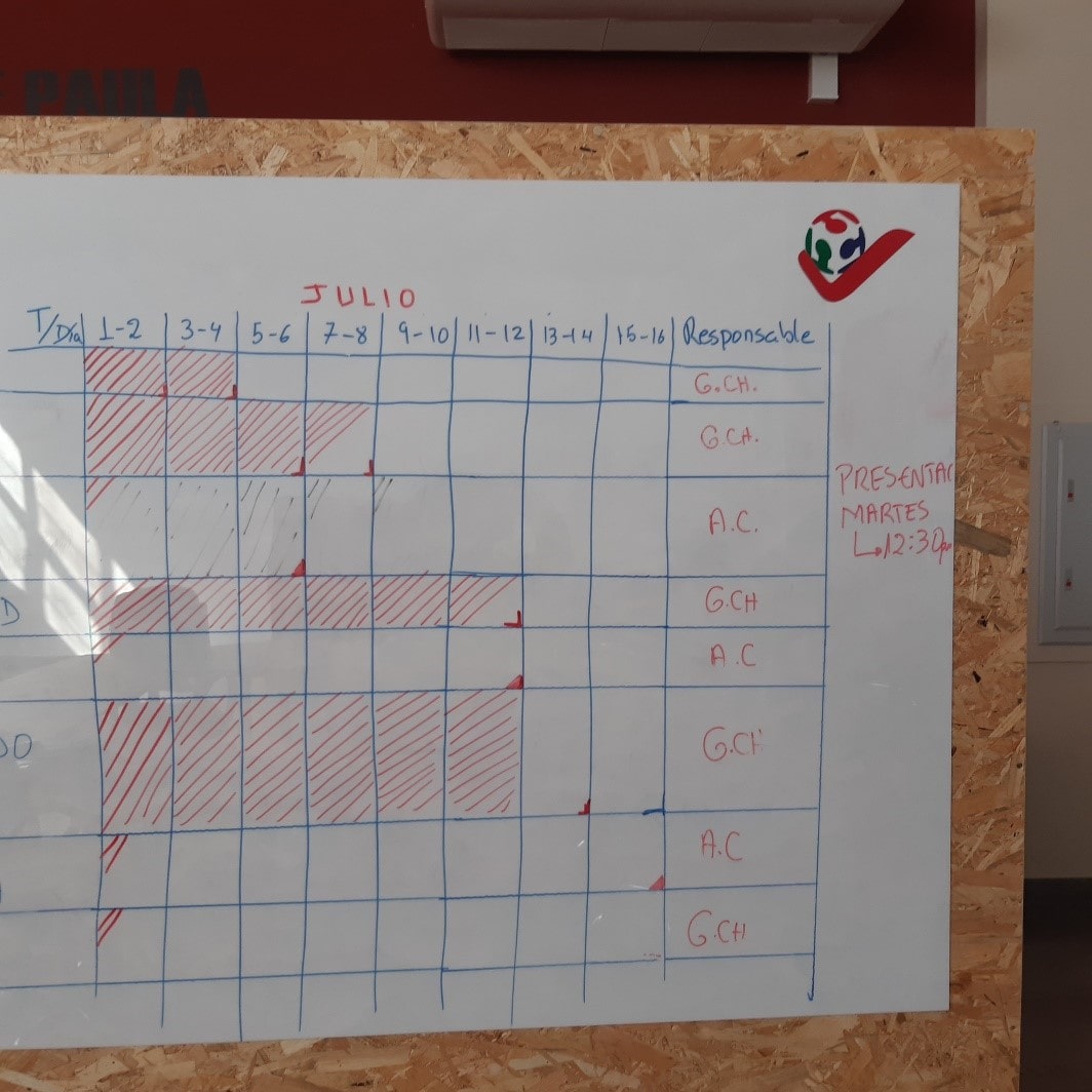
Not bad, right?
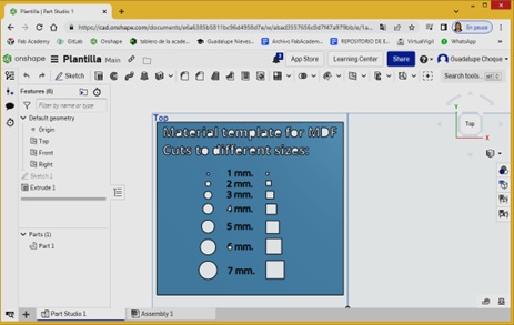
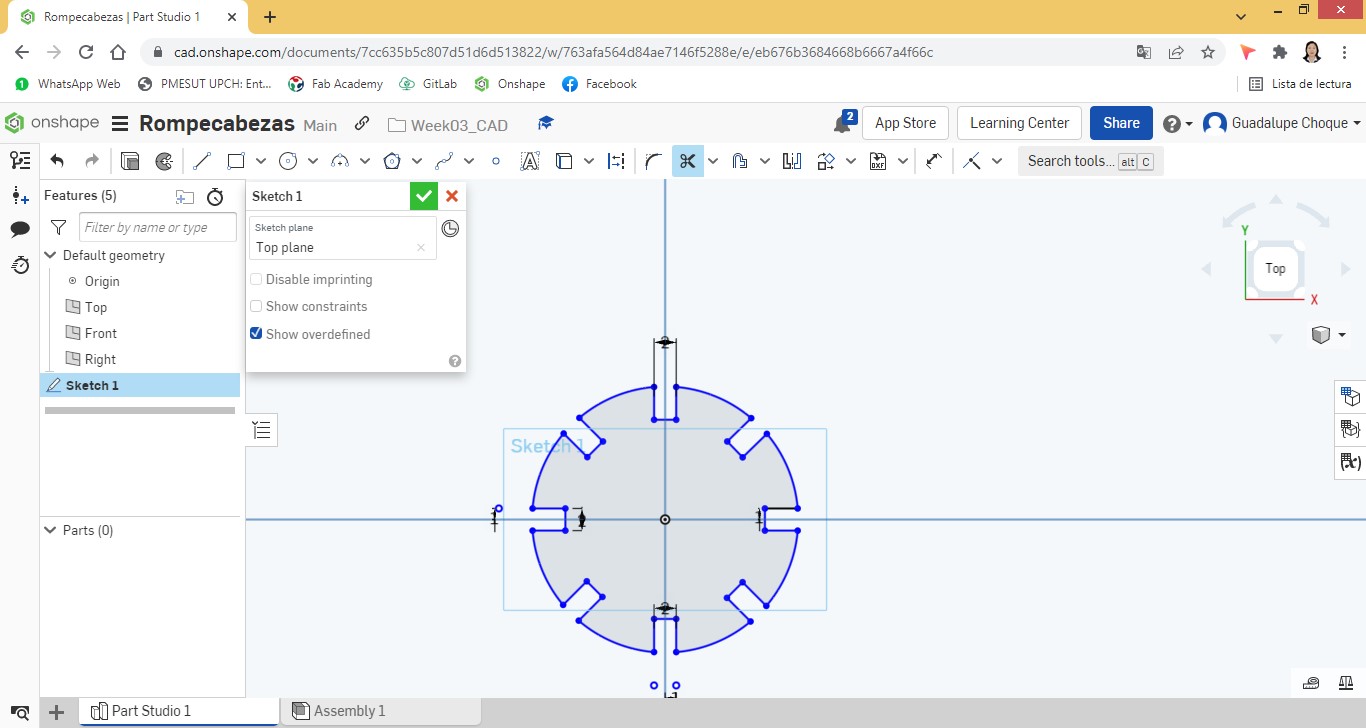
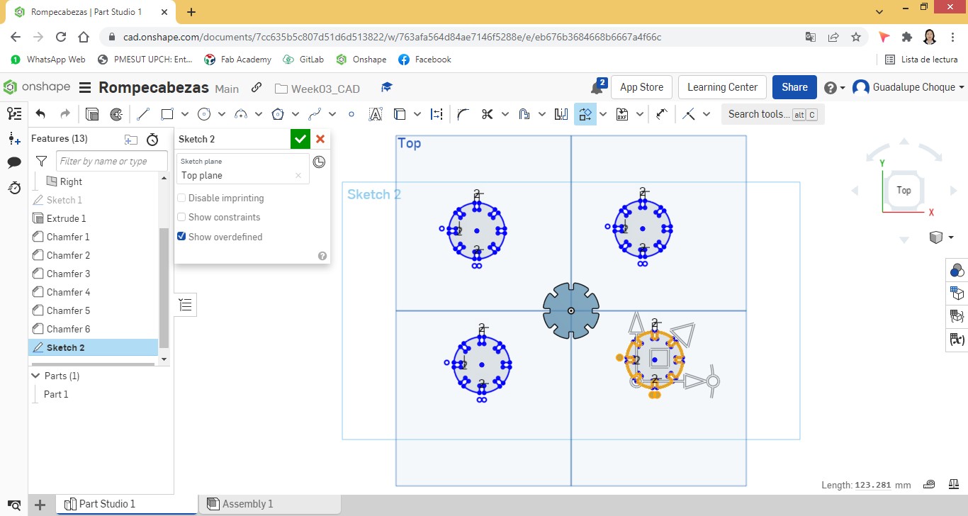
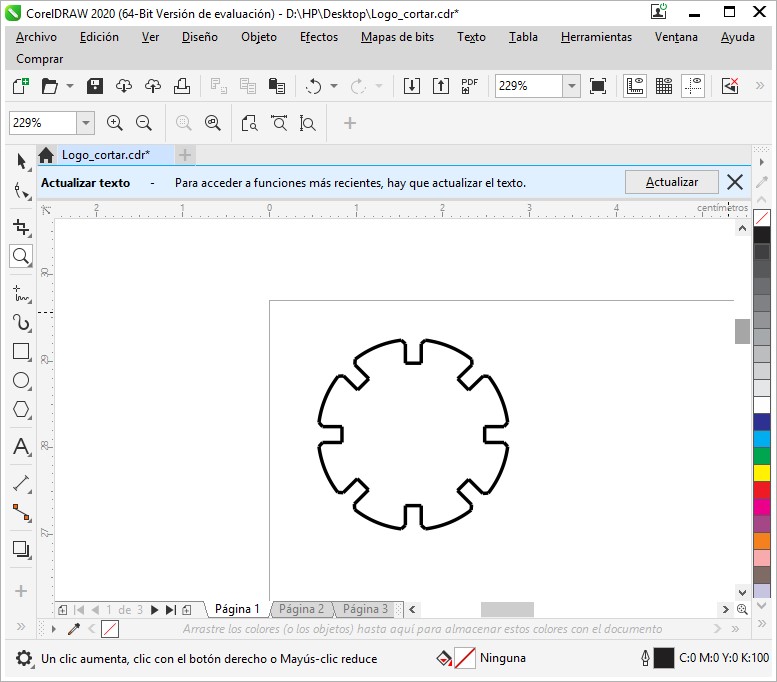
The kit was worked based on the design of a single piece, the same one that was made in Onshape. Initially a circular basic figure with a diameter of 24cm was inserted. To which was added rectangles that would later be tickets.
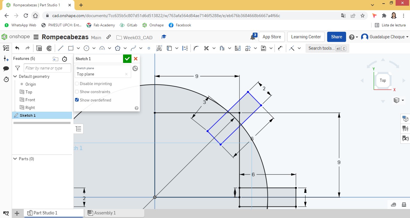
A total of 8 rectangles were added to the figure, distributed every 45°.
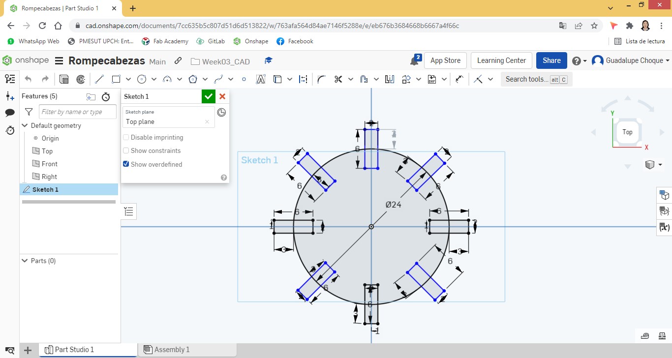
Intersection nodes were added and then trimmed.
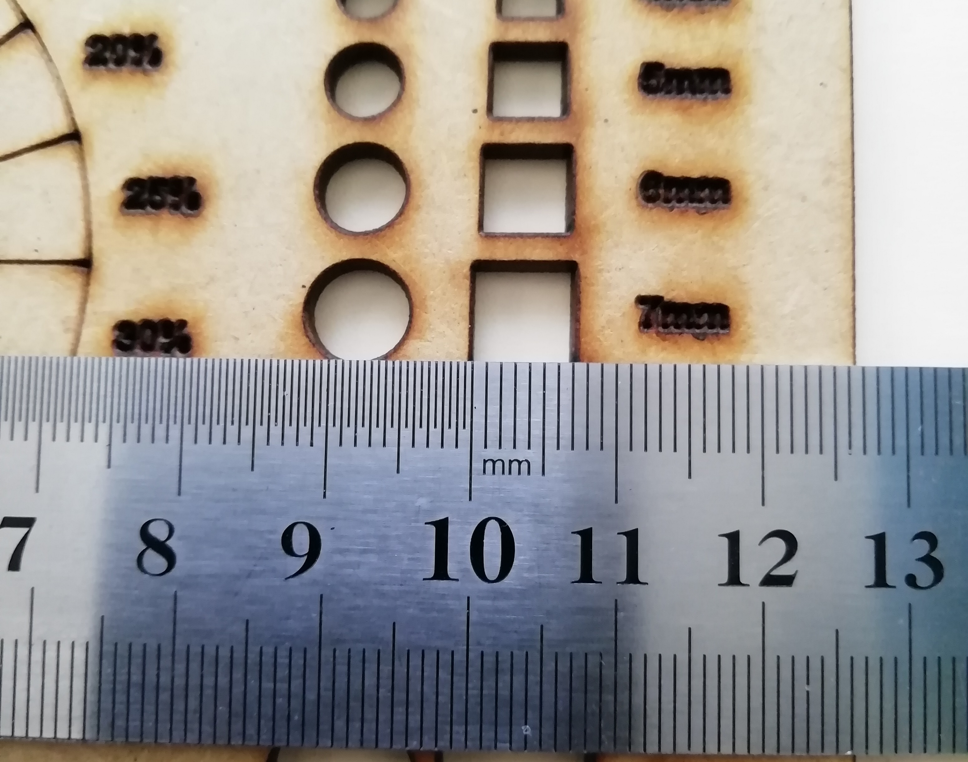
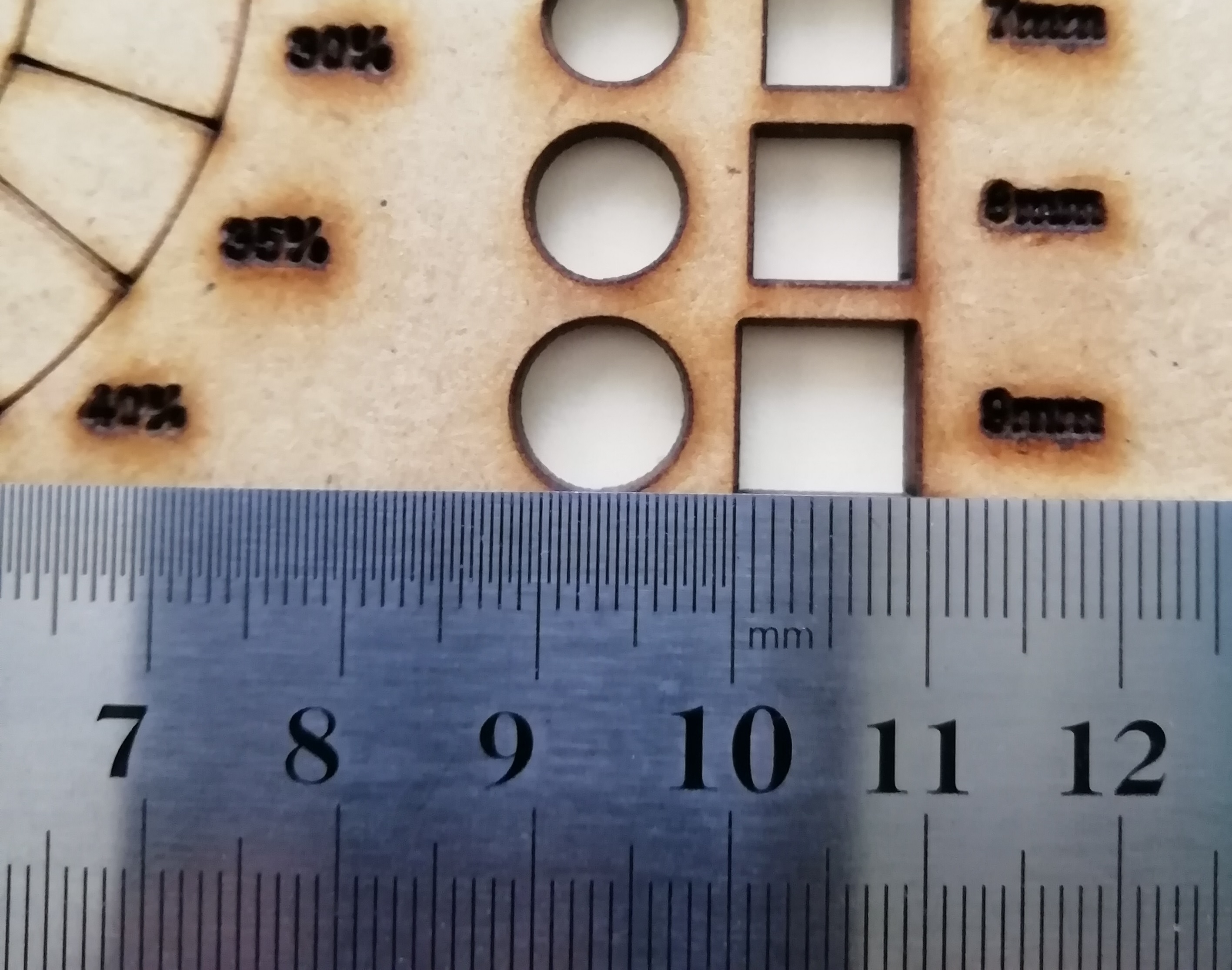
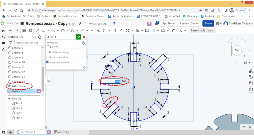
Since the distance or height between the outer and inner edge of the part is exactly the same on all eight sides, it is convenient to apply parametric design. For this I have created the variable Alt and I have assigned the value of 3mm. Every time I wanted to assign a value to each height, I simply called the #Alt variable and it automatically assigned the value 3mm. Given the desire to want to change the distance or height of all the inputs, it will suffice to change the value of the variable, this will affect all the heights of the inputs.
The #Esp variable was also created, as part of the parametric design, which will allow the value of 2mm to be assigned to all entries in the piece. The benefits are exactly the same as the #Alt variable.
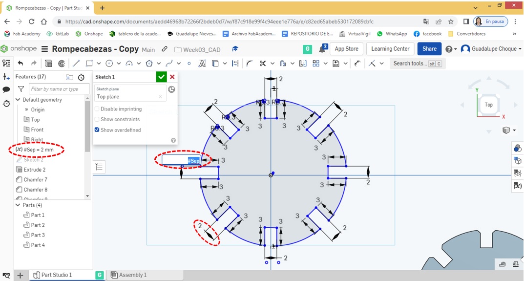
With the application of parametric design, it is possible to significantly reduce the effort and time when carrying out any design, in addition to reducing the risk of making mistakes.
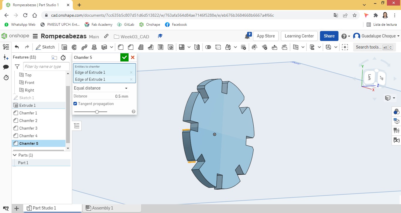
Continuing with the design, then Extrude was applied to obtain the figure in 3D and Chamfer so that the edges of the rectangles are rounded.
Continuing with the design, then Extrude was applied to obtain the figure in 3D and Chamfer so that the edges of the rectangles are rounded.
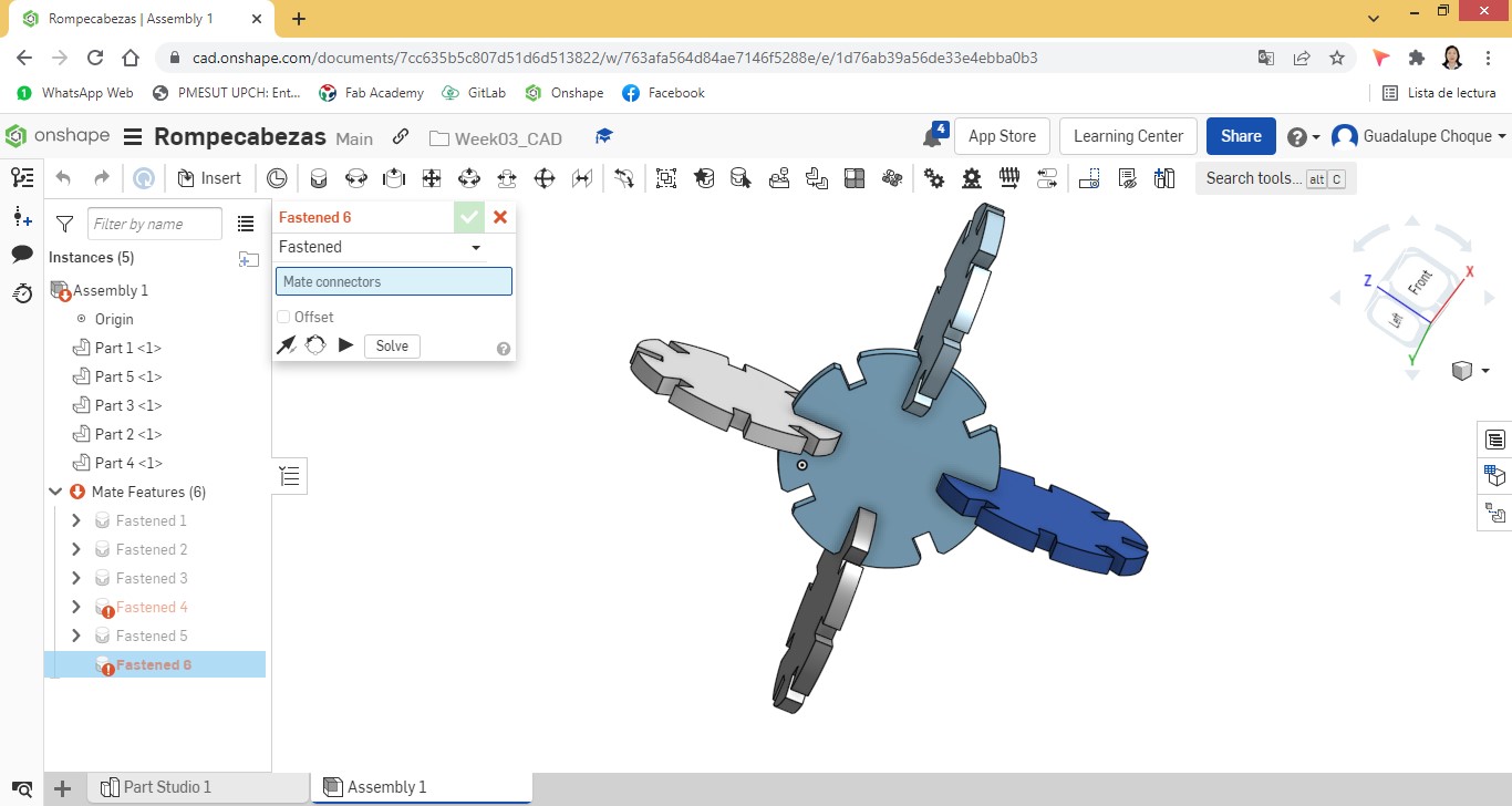
Copies of the part were made to later insert them into the assembly area.
Find me in the assembly area I proceeded to put the pieces together.
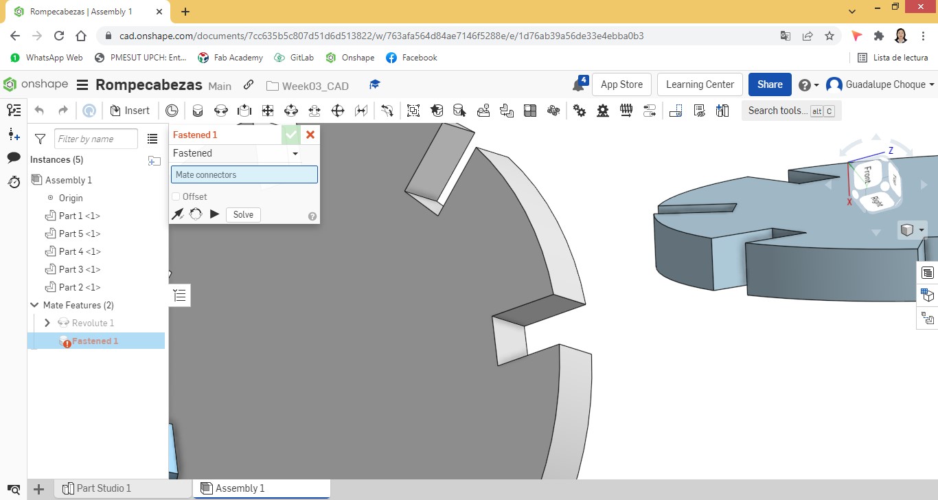
The 5 pieces ended up together with the following appearance:
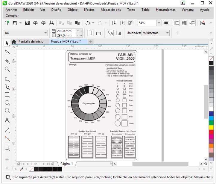
Then the design was exported to Corel Draw and from there prepare it for its respective laser cut in cardboard material.
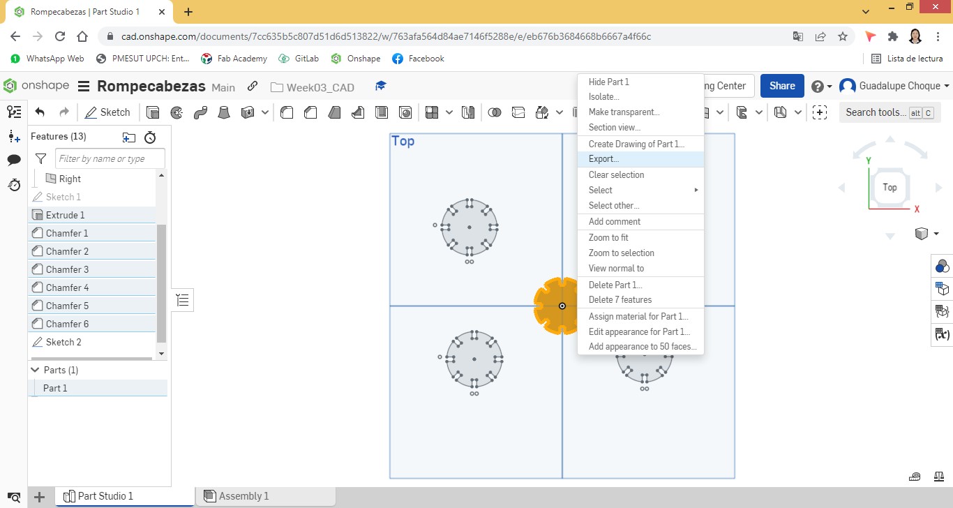
The piece in Corel Draw.
Once the design is completed, the laser service is requested again for its respective cut. Using cutting software, the operator set up the cutter, telling me that all 96 pieces would be cut in approximately 10 minutes.
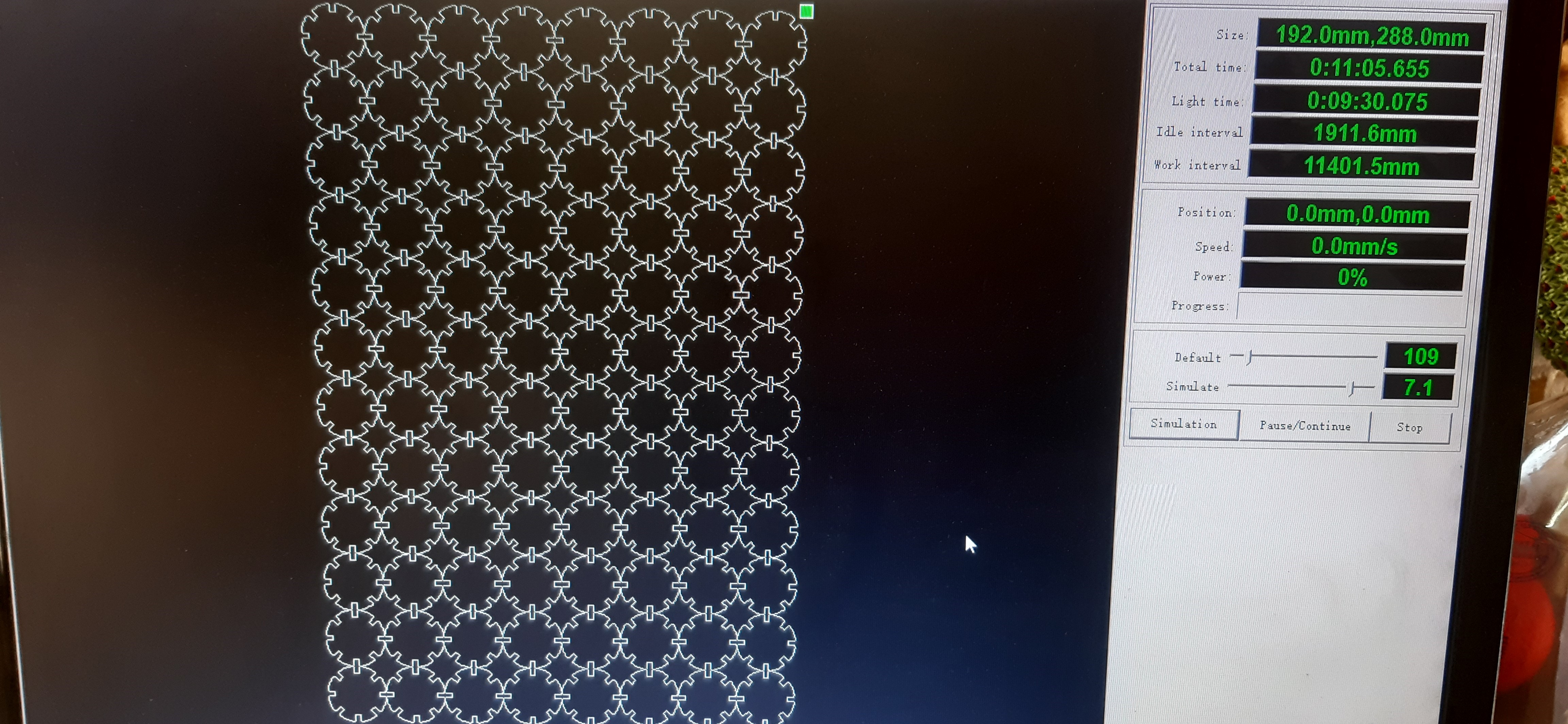
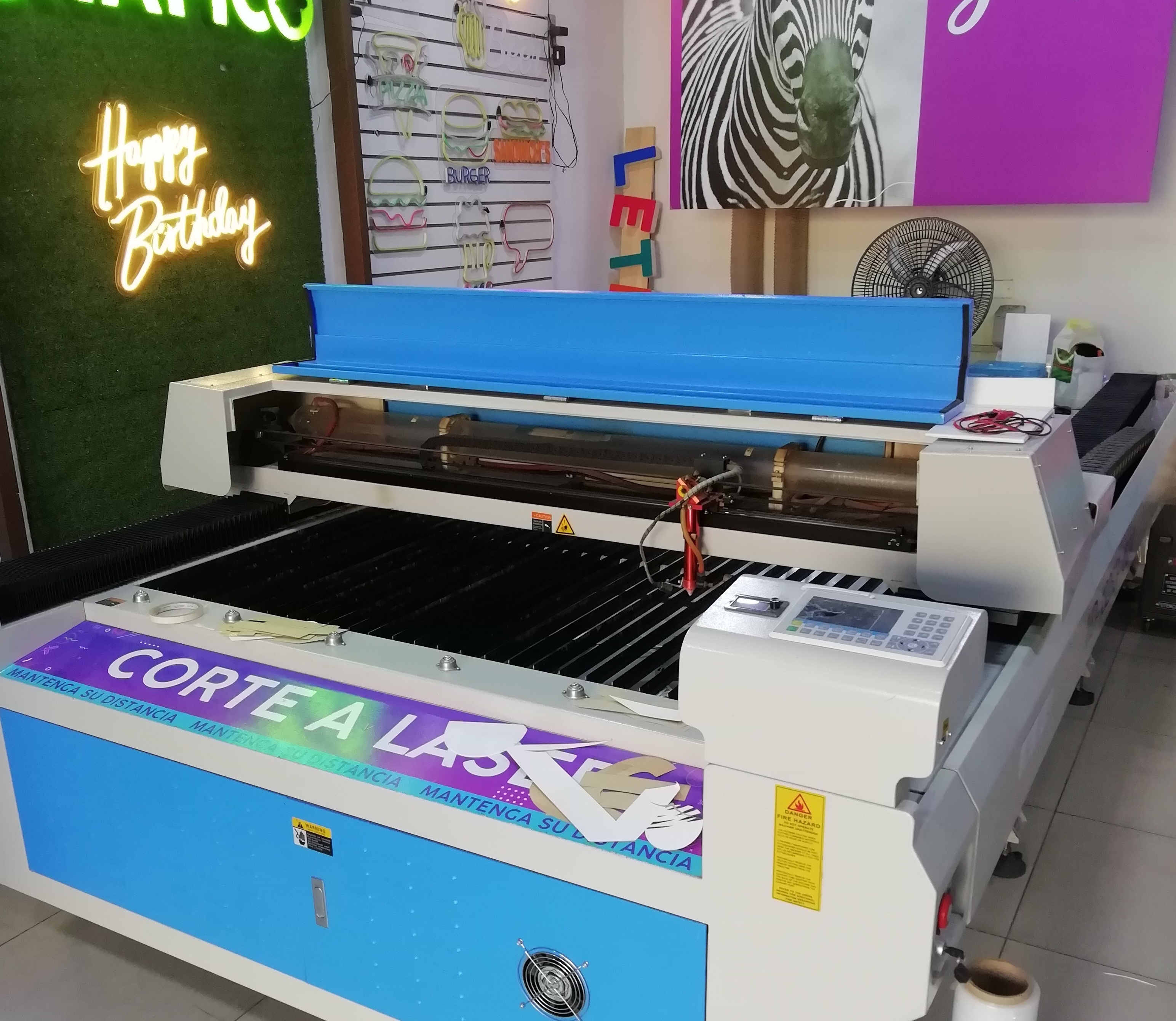
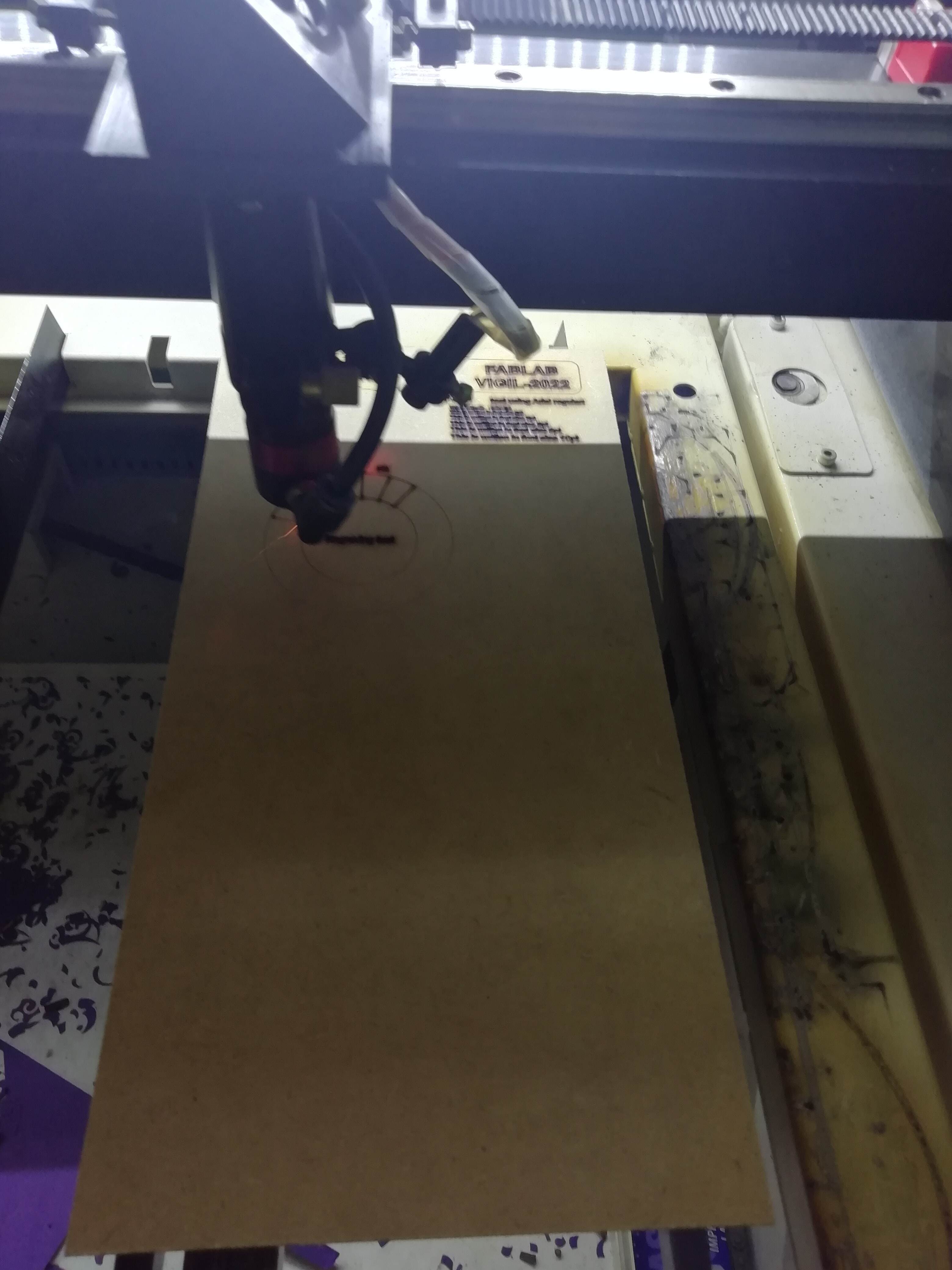
Now if we had already had a digital manufacturing laboratory at that time, we would have used the Storm 600 model laser cutter.
This cutter works with the CNCLaser software.
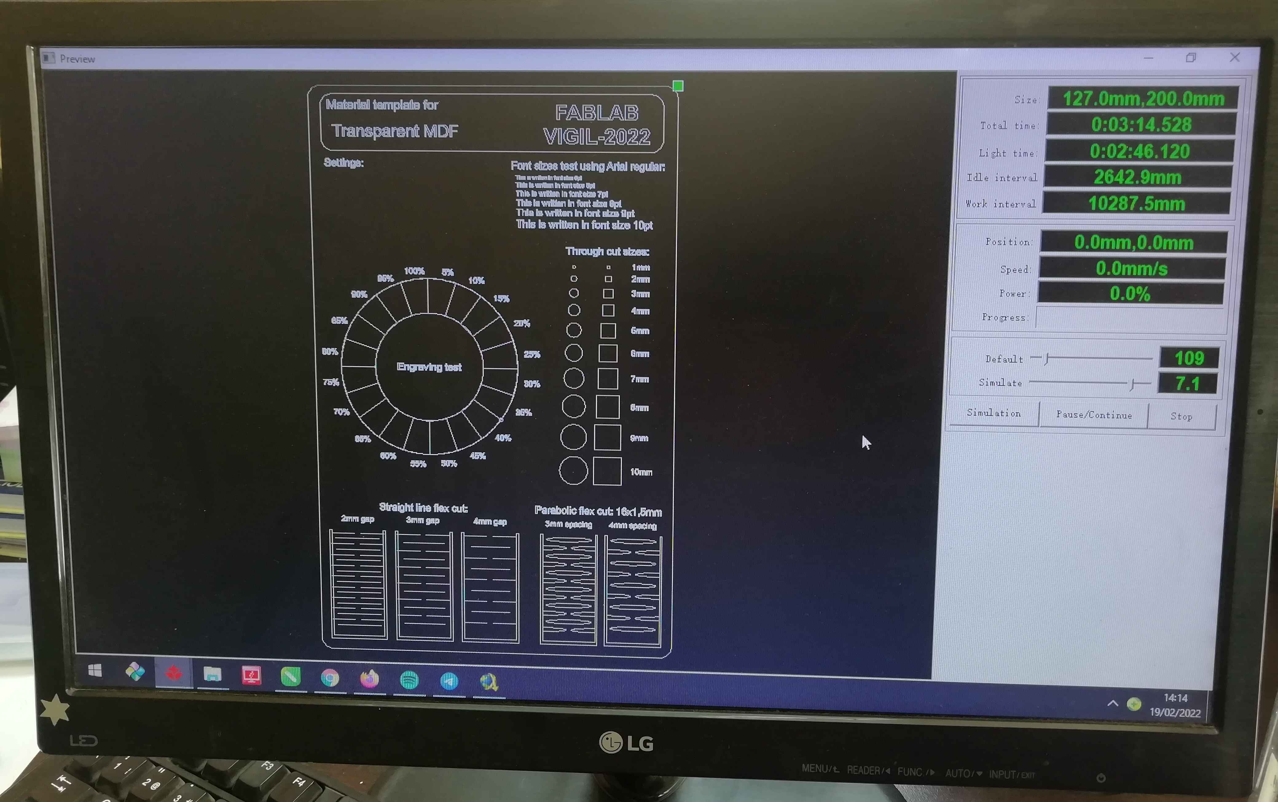
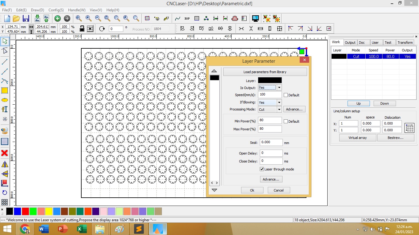
Once the DXF file is loaded, we proceed to the configuration of the cut.
Basically speed and power values are assigned.
As it is about cutting cardboard material, it is assigned:
Min y Max Power: 80%
Speed: 100 mm/s
Cut the pieces were like this:
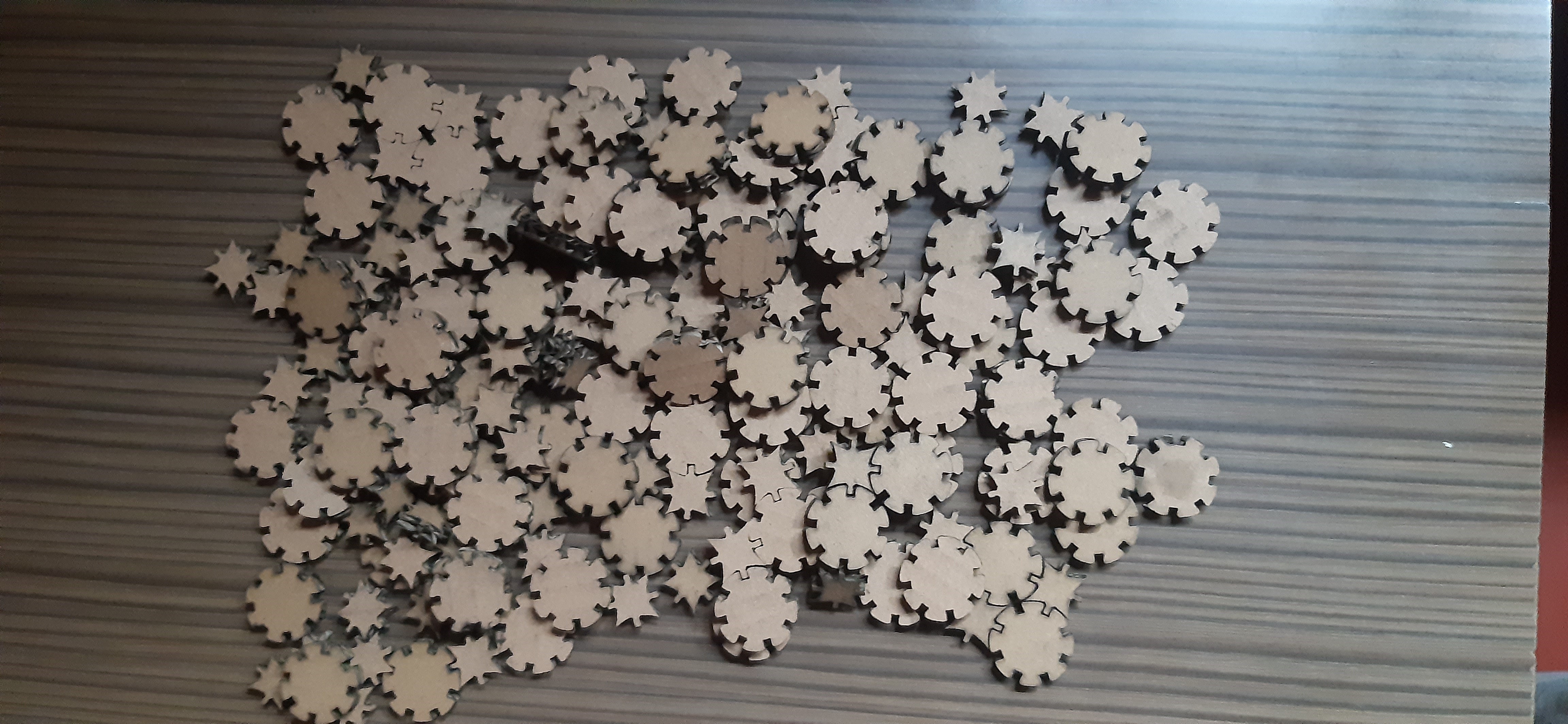
At the time of trying to assemble the pieces, I realized that the entrances of the pieces did not fit between them. This was due to the fact that the material was thicker than 2 mm, a measure that had been considered in the design.
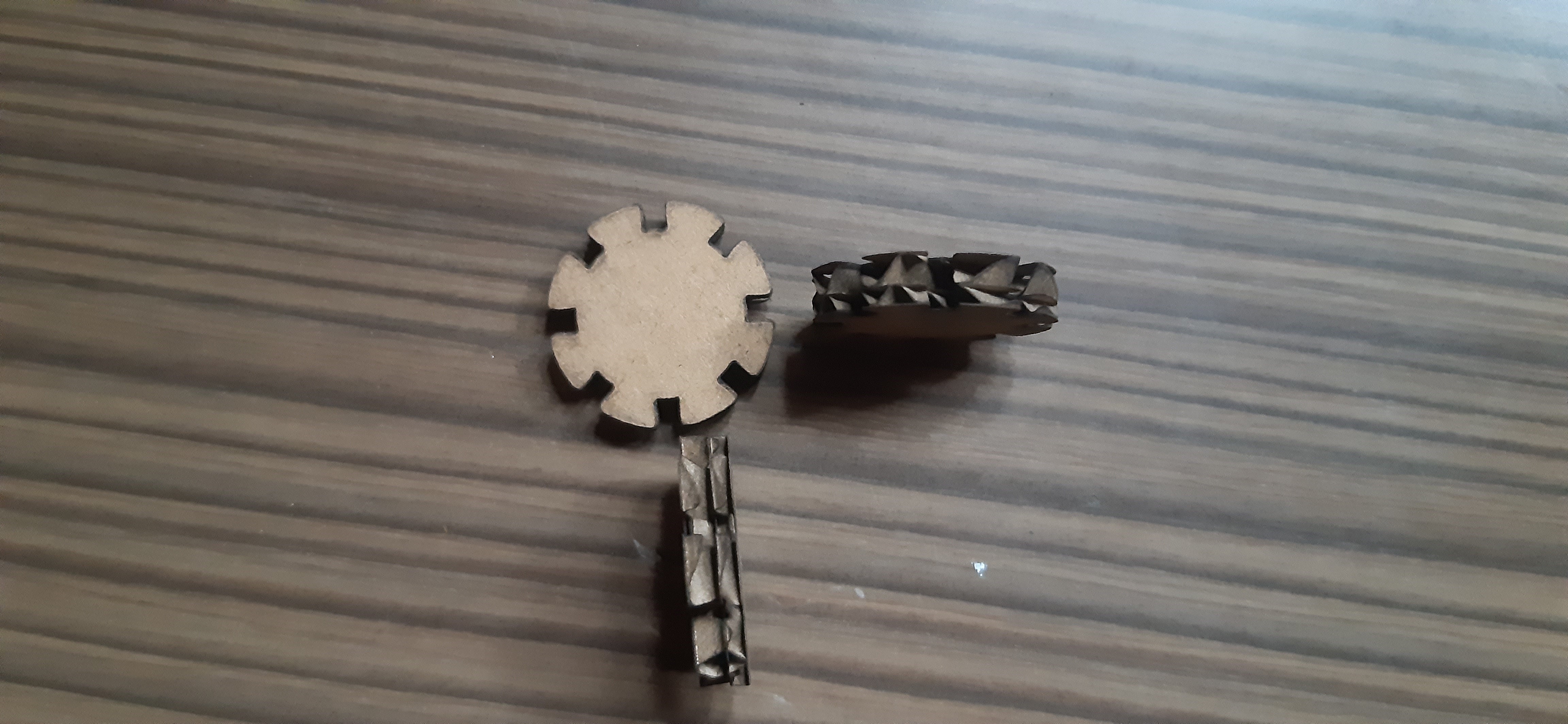
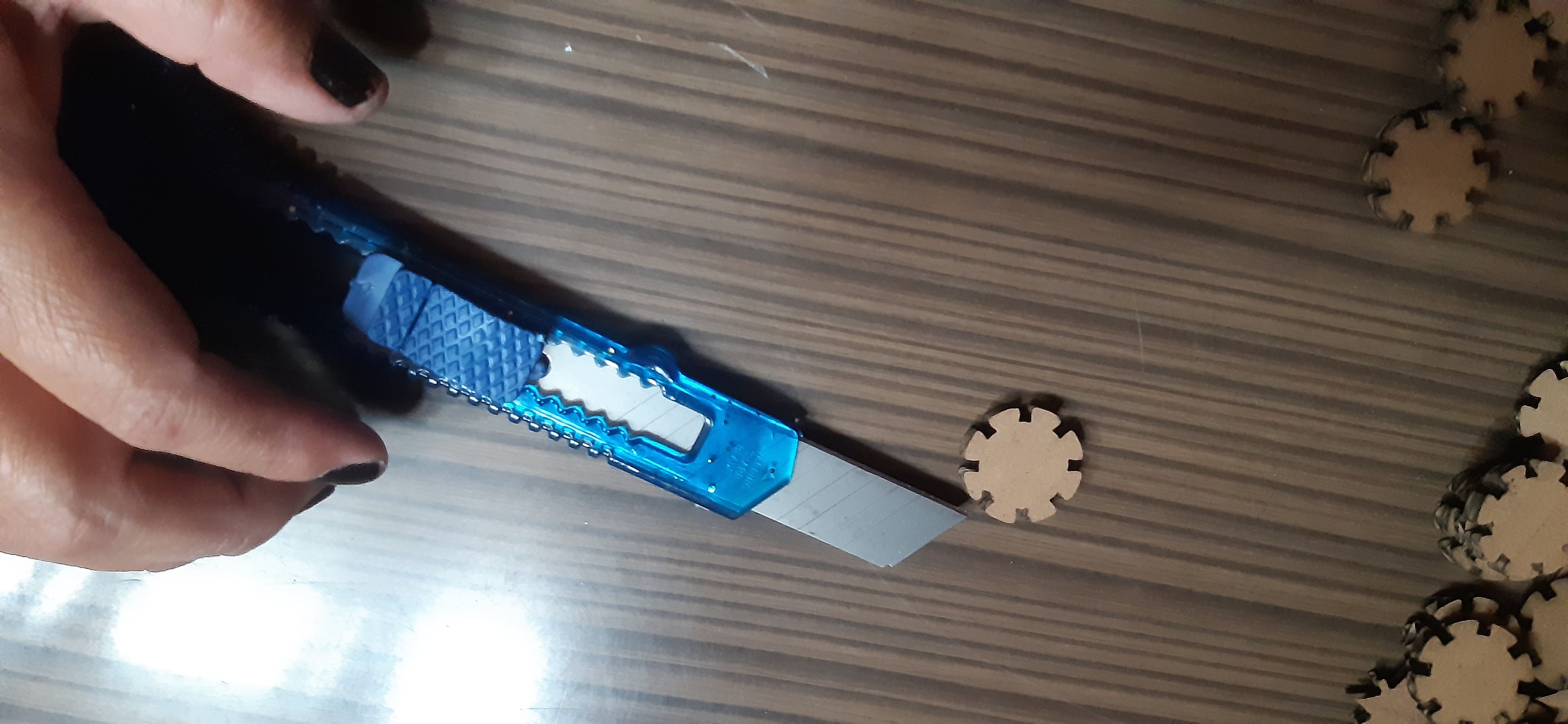
As a solution for the entrances of the pieces to fit, was to cut them in the middle, with the help of a cutter, although that would imply that the pieces are a little weaker.
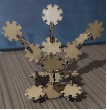
Having already cut the pieces, we proceeded to shape them. It started with the design of a clover.
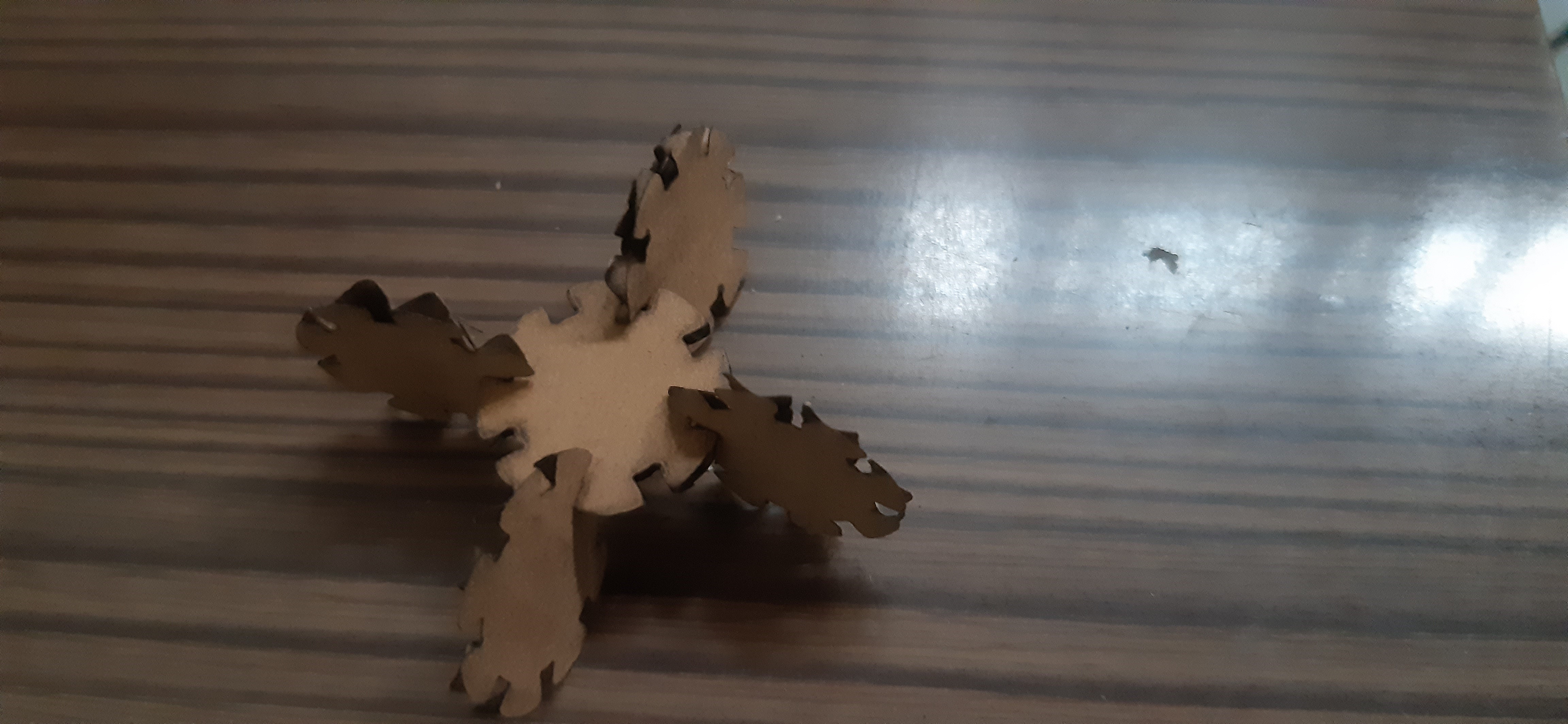
Continuing with the assembly of an airplane.
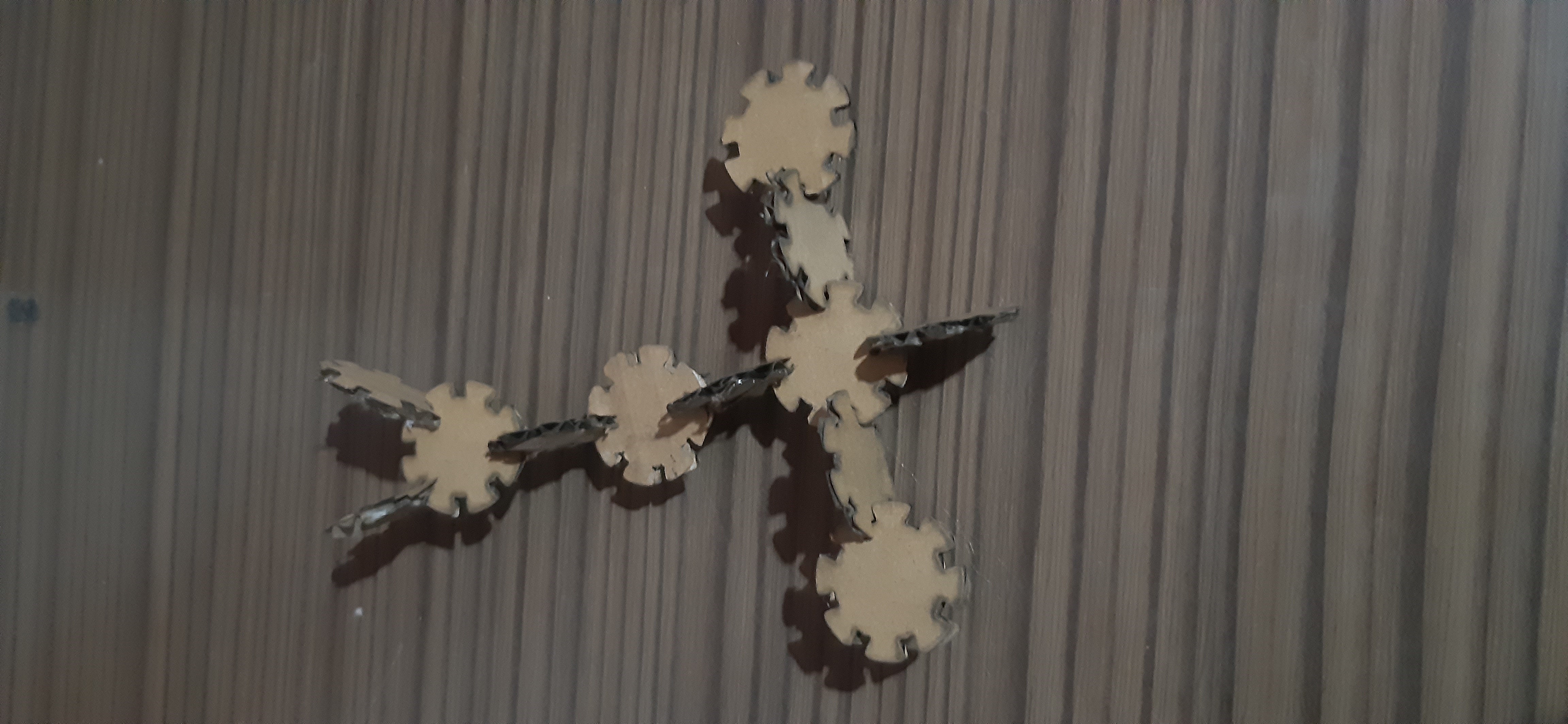
And ending with the design of a peacock.
Natives files
| Ord | Description | Files |
|---|---|---|
| 1 | Logo design | Logo FabLab Vigil |
| 2 | Parametric design | Parametric Kit |