9. Embedded programming
Working individually
Using one of the main internet search engines I found technical information about ATtiny44A/ATtiny44A/ATtiny84A at the URL https://www.alldatasheet.com/

ATtiny44A/ATtiny44A/ATtiny84A
Attiny44 is a low power CMOS 8-bit microcontroller based on AVR's Enhanced RISC architecture.
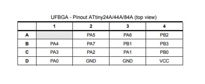
Pin configurations
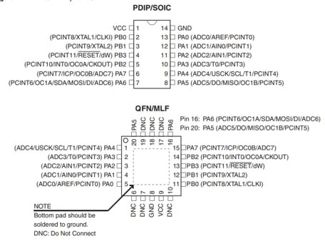
Pin Descriptions
VCC : Supply voltaje
GND : Ground
Port B (PB3:PB0) :
Port B is a 4-bit bi-directional I/O port with internal pull-up resistors (selected for each bit). The Port B output buffers have symmetrical drive characteristics with both high sink and source capability except PB3 which has the RESET capability. To use pin PB3 as an I/O pin, instead of RESET pin, program (‘0’) RSTDISBL fuse. As inputs, Port B pins that are externally pulled low will source current if the pull-up resistors are activated. The Port B pins are tri-stated when a reset condition becomes active, even if the clock is not running.
Port B also serves the functions of various special features of the ATtiny24/44/84.
RESET :
Reset input. A low level on this pin for longer than the minimum pulse length will generate a reset, even if the clock is not running and provided the reset pin has not been disabled.
The reset pin can also be used as a (weak) I/O pin.
Port A (PA7:PA0) :
Port A is a 8-bit bi-directional I/O port with internal pull-up resistors (selected for each bit). The Port A output buffers have symmetrical drive characteristics with both high sink and source capability. As inputs, Port A pins that are externally pulled low will source current if the pull-up resistors are activated. The Port A pins are tri-stated when a reset condition becomes active, even if the clock is not running.
Overview
ATtiny24/44/84 is a low-power CMOS 8-bit microcontroller based on the AVR enhanced RISC architecture. By executing powerful instructions in a single clock cycle, the ATtiny24/44/84 achieves throughputs approaching 1 MIPS per MHz allowing the system designer to optimize power consumption versus processing speed.
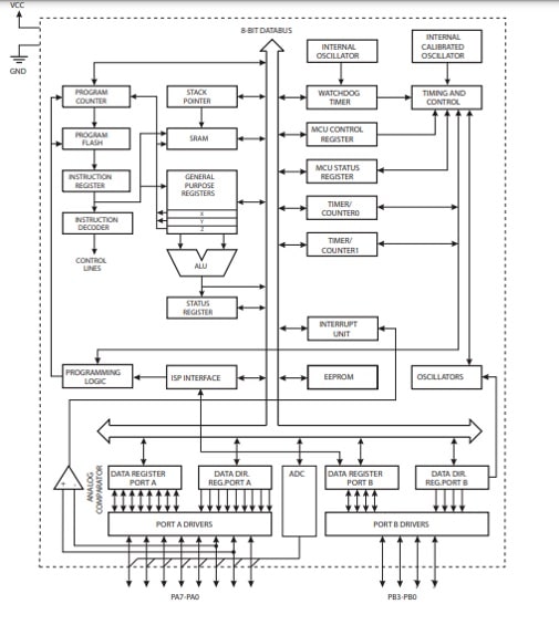
The AVR core combines a rich instruction set with 32 general purpose working registers. All 32 registers are directly connected to the Arithmetic Logic Unit (ALU), allowing two independent registers to be accessed in one single instruction executed in one clock cycle. The resulting architecture is more code efficient while achieving throughputs up to ten times faster than conventional CISC microcontrollers.
The ATtiny24/44/84 provides the following features: 2/4/8K byte of In-System Programmable Flash, 128/256/512 bytes EEPROM, 128/256/512 bytes SRAM, 12 general purpose I/O lines, 32 general purpose working registers, an 8-bit Timer/Counter with two PWM channels, a 16-bit timer/counter with two PWM channels, Internal and External Interrupts, a 8-channel 10-bit ADC, programmable gain stage (1x, 20x) for 12 differential ADC channel pairs, a programmable Watchdog Timer with internal oscillator, internal calibrated oscillator, and four software selectable power saving modes. Idle mode stops the CPU while allowing the SRAM, Timer/Counter, ADC, Analog Comparator, and Interrupt system to continue functioning. ADC Noise Reduction mode minimizes switching noise during ADC conversions by stopping the CPU and all I/O modules except the ADC. In Power-down mode registers keep their contents and all chip functions are disbaled until the next interrupt or hardware reset. In Standby mode, the crystal/resonator oscillator is running while the rest of the device is sleeping, allowing very fast start-up combined with low power consumption. The device is manufactured using Atmel’s high density non-volatile memory technology. The onchip ISP Flash allows the Program memory to be re-programmed in-system through an SPI serial interface, by a conventional non-volatile memory programmer or by an on-chip boot code running on the AVR core.
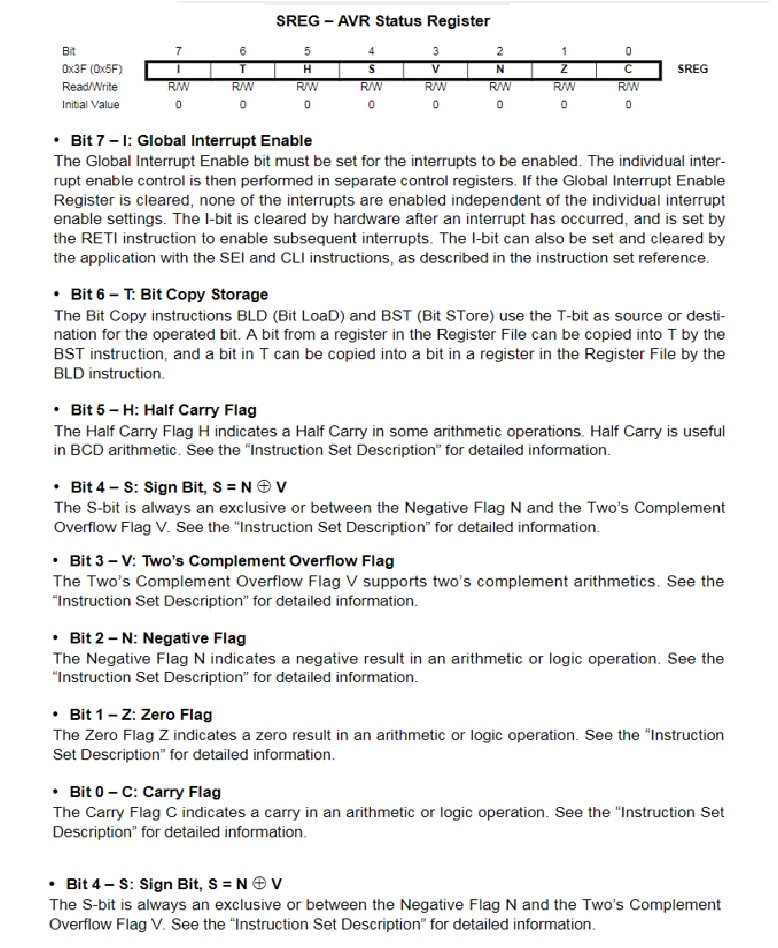
In the following Figure we can see the SREG register to control the Counter Program:
General Purpose Register File
The Register File is optimized for the AVR Enhanced RISC instruction set. In order to achieve the required performance and flexibility, the following input/output schemes are supported by the Register File:
• One 8-bit output operand and one 8-bit result input
• Two 8-bit output operands and one 8-bit result input
• Two 8-bit output operands and one 16-bit result input
• One 16-bit output operand and one 16-bit result input
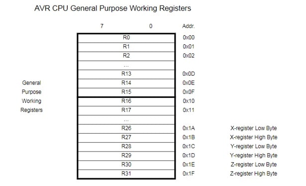
Most of the instructions operating on the Register File have direct access to all registers, and most of them are single cycle instructions.
As shown in Figure, each register is also assigned a Data memory address, mapping them directly into the first 32 loca tions of the user Data Space.
Although not being physically imple-mented as SRAM locations, this memory organization provides great flexibility in access of the registers, as the X-, Y- and Z-pointer registers can be set to index any register in the file.
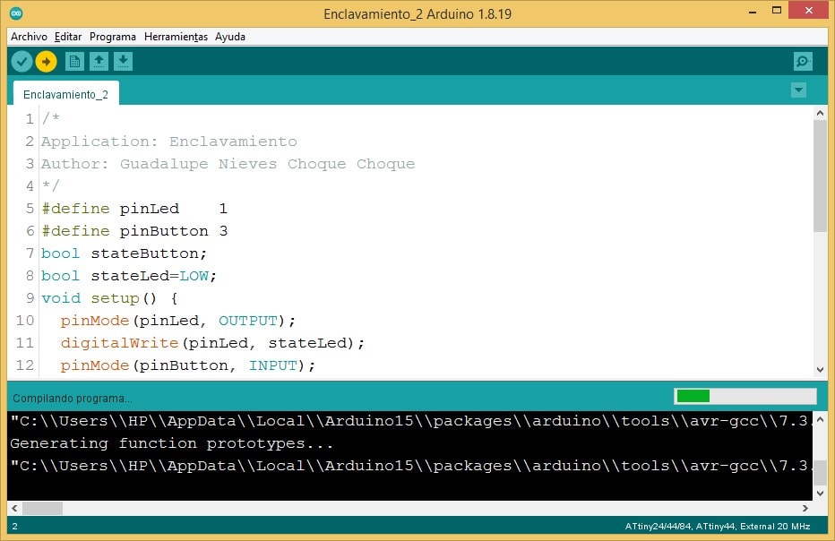
Application No. 01: Interlock
Using the Arduino software and considering the ATtiny44A microcontroller, an interlock application was developed, the same one that would work from pressing a button to turning on an LED and turning it off by pressing the button again.
The corresponding code is:
/*
Application: LED - Button
Author: Guadalupe Nieves Choque Choque
*/
#define pinLed    1
#define pinButton 3
bool stateButton;
bool stateLed=LOW;
void setup() {
  pinMode(pinLed, OUTPUT);
  digitalWrite(pinLed, stateLed);
  pinMode(pinButton, INPUT);
  stateButton = digitalRead(pinButton);
}
void loop() {
  if (digitalRead(pinButton)!=stateButton){
    stateButton = digitalRead(pinButton);
    if (stateButton){
      stateLed = !stateLed;
      digitalWrite(pinLed, stateLed);
    }
    else{
    }
  }
}
Showing the instructions on the Arduino.
Observing the execution physically.
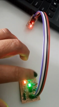
Demonstration of the operation of the application.
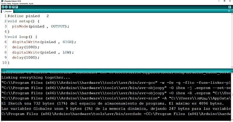
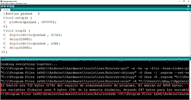
Application No. 02: Flashing
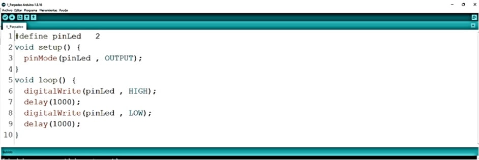
A very simple application is going to be developed, where when executed, only the LED blinking is achieved, but this time using ESP32.
Starting with the implementation of the program. Only working with the necessary instructions.
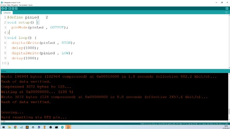
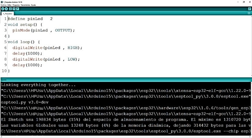
#define pinLed   2
void setup() {
  pinMode(pinLed , OUTPUT);
}
void loop() {
  digitalWrite(pinLed , HIGH);
  delay(1000);
  digitalWrite(pinLed , LOW);
  delay(1000);
}
Taking him to the coding area.
Now it is time to configure the ESP32 on the Arduino.
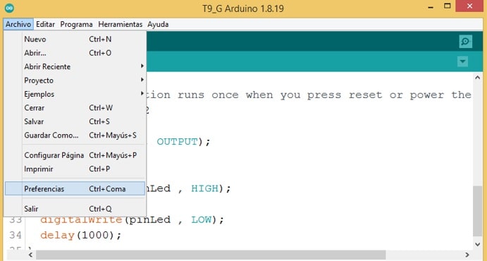
To configure, you must go to File from the Arduino menu bar and select Preferences.
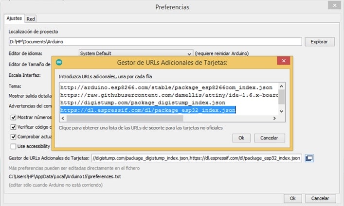
In the Additional Card URLs manager, add the link https://dl.espressif.com/dl/package_esp32_index.json, page that contains the ESP32 instructions package. Confirm with Ok.
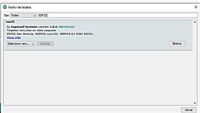
Go to Tools/Board “[microcontroller_name]” and select Card Manager.
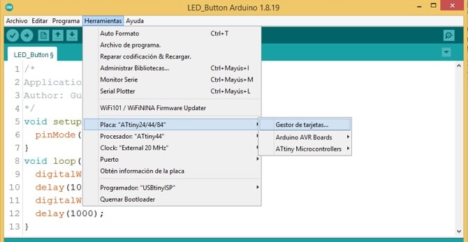
Enter ESP32 in the search box and click Install.
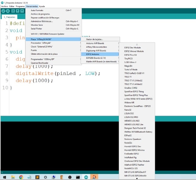
Go to Tools and select For ATtiny, ESP32 Arduino.
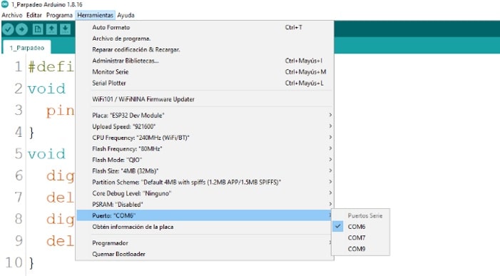
Then choose COM6 port.
Clever!!!
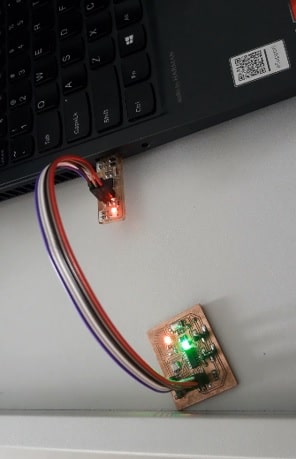
Once the configuration is finished, I run the blinking application, already worked on previously.
Observing the physical result.
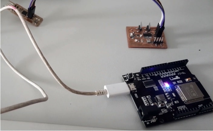
The video shows the execution of the application.
Working in group
For the resolution of this work block, a comparison was made between the work performance of ATtiny44A and esp32.
Before making a technical comparison between both platforms, I will give some esp32 references. With reference to ATtiny44A it was already dealt with in the first part of this work.
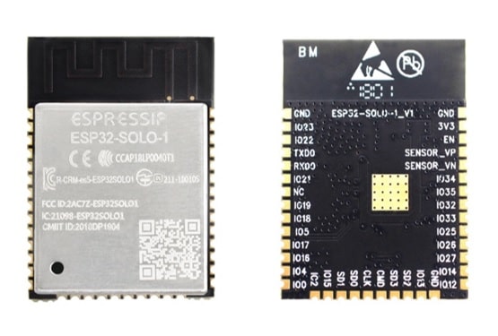
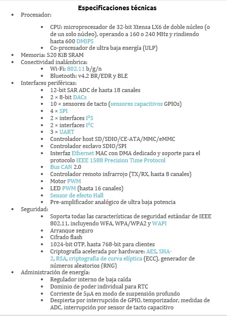
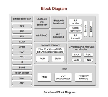
Esp32
Information about the Esp32 microcontroller was located on the page ESP32 Family Microcontrollers (https://www.smartopenlab.com/
)
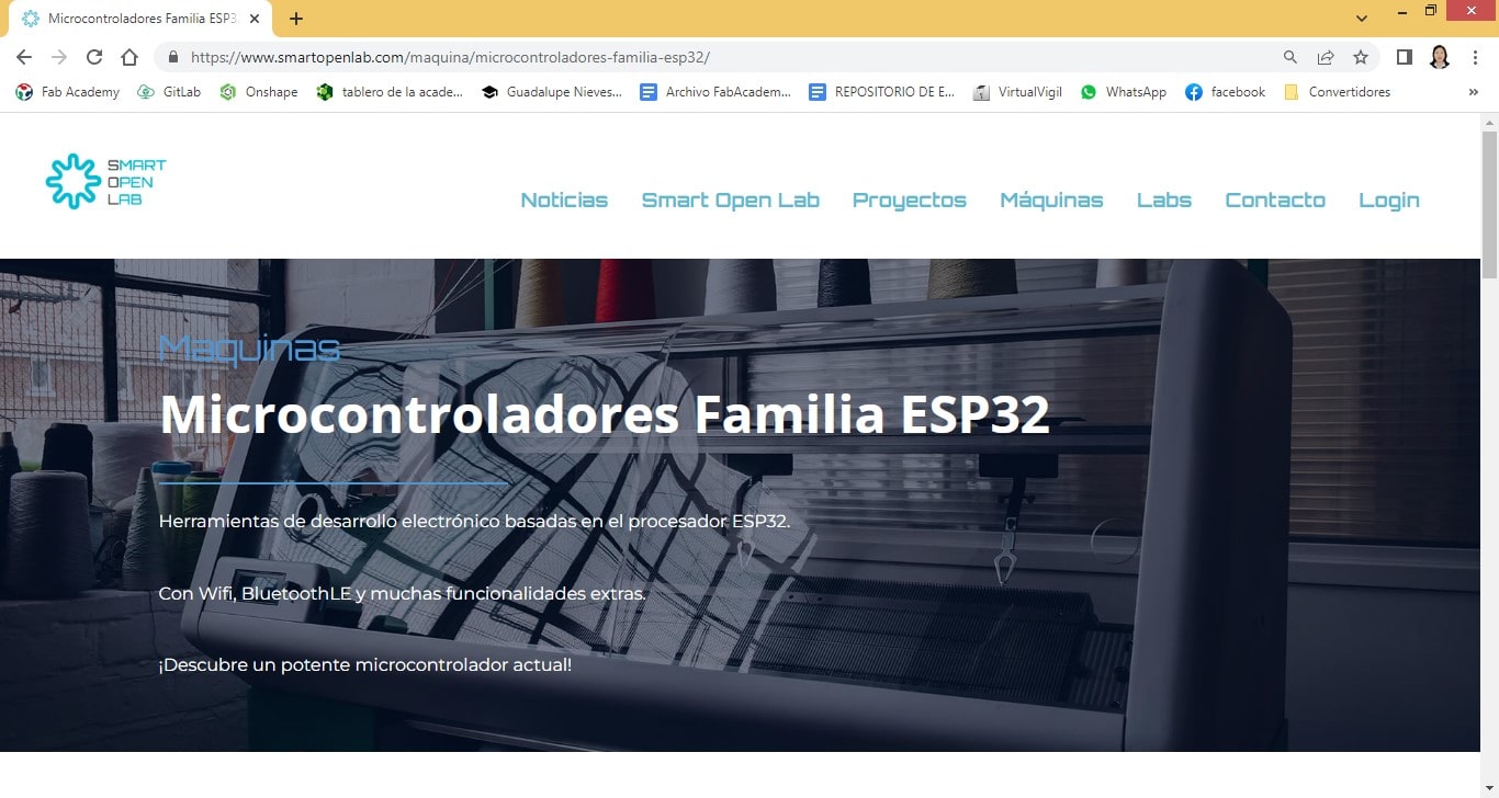
ESP32 is a series of low-cost, low-power system-on-a-chip microcontrollers with integrated Wi-Fi and dual-mode Bluetooth. The ESP32 series employs a Tensilica Xtensa LX6 microprocessor in dual-core and single-core variations or a single-core RISC-V microprocessor and includes integrated antenna switches, RF balun, power amplifier, low noise receive amplifier , filters and power management modules. ESP32 is created and developed by Espressif Systems, a Shanghai-based Chinese company, and is manufactured by TSMC using their 40nm process. [2] It is a successor to the ESP8266 microcontroller.
Having concluded with the descriptive references, a comparison is made between the workflows between both work microcontrollers. For this, the execution of the Blinking application with the two microcontrollers has been considered.
What is missing is the execution of the blinking application with ATtiny44A, therefore we proceed to do it.
Appreciating the results physically.
Demonstration of running the application on the video.
Considering both results, a comparison of the workflows can be made.
ESp32
ATtiny44A
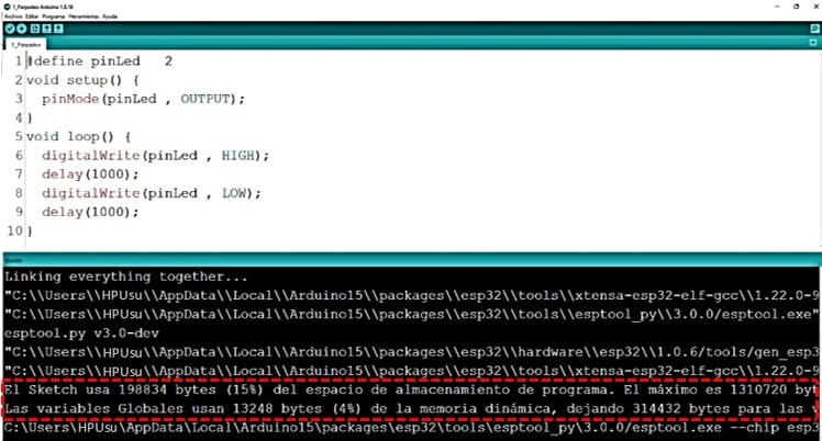
Comparison
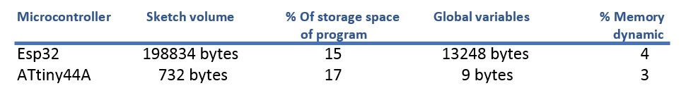
What the data sheets state clearly states, the ATtimy44A microcontroller allows applications developed in the programming language to occupy a minimum of storage space. That is one of the benefits, among others, that this microcontroller has.
Natives files
| Ord | Description | Files |
|---|---|---|
| 1 | App Flicker | App_Flicker.ino |
| 2 | App Interlock | App_Interlock.ino |