6. 3D Scanning and printing
Working in group
1. Characterization of the printing rules of your 3D printer(s)
This week it is our turn as a group to characterize the printing of the 3D printer. To do this we searched the web for some patterns that meet specific details such as bridges, angles, cylinders of different diameters, conical tips among others.
We found many shapes, some simple and others more complex. After several hours of searching, we were left with the open source evaluation model, which employs numerous elements, in order to test the accuracy, resolution and alignment of 3D printers.
The image below shows the 7 descriptive elements of the pattern part.
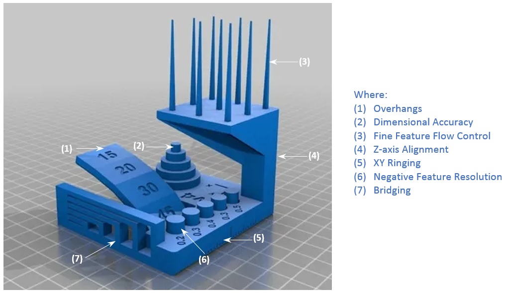
This open source model offers a standard test to evaluate the performance of 3D printers, i.e. when printing this is subjected to extreme test of their movements, speed, roughness, nozzle heating, minimum angle of the stepper motors, among others; but the interesting feature is that the pattern model is small in size.
We locate on the internet the file with .stl extension in the link https://github.com/kickstarter/kickstarter-autodesk-3d/tree/master/FDM-protocol, download it and open it in the popular software for 3D printers, Ultimaker Cura (there are several).
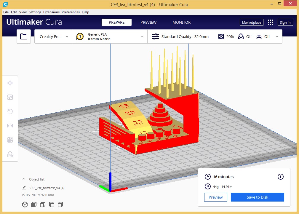
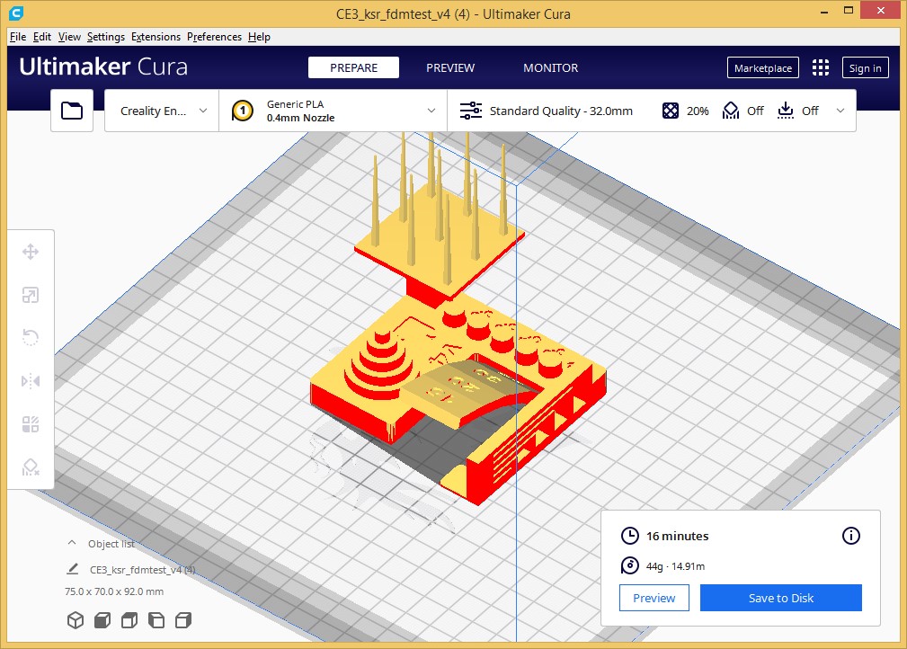
We customize it for printing is done through the assignment of properties.
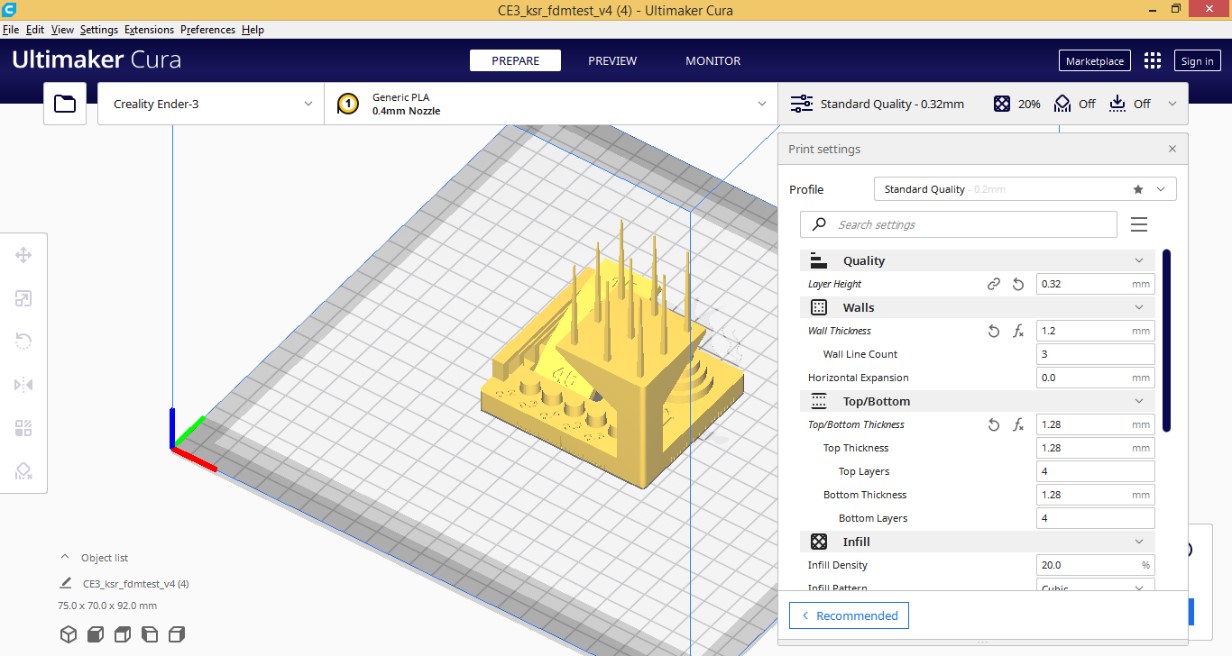
We finally have the pattern, we know the printer settings and we are ready to 3D print it.
2. Testing with Pattern
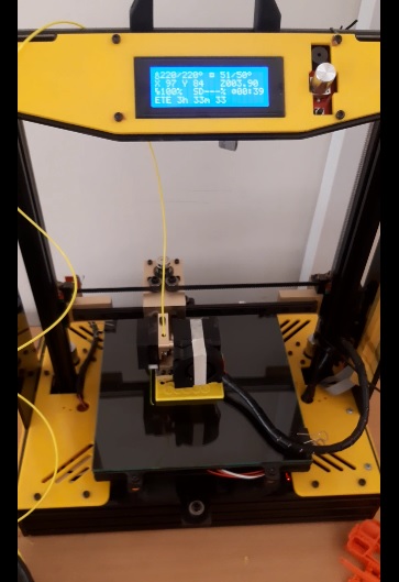
The 3D printer is a Prusa i4 model (Chinese manufacturing) and its program with which it works is the Repetier Host V2.2.4
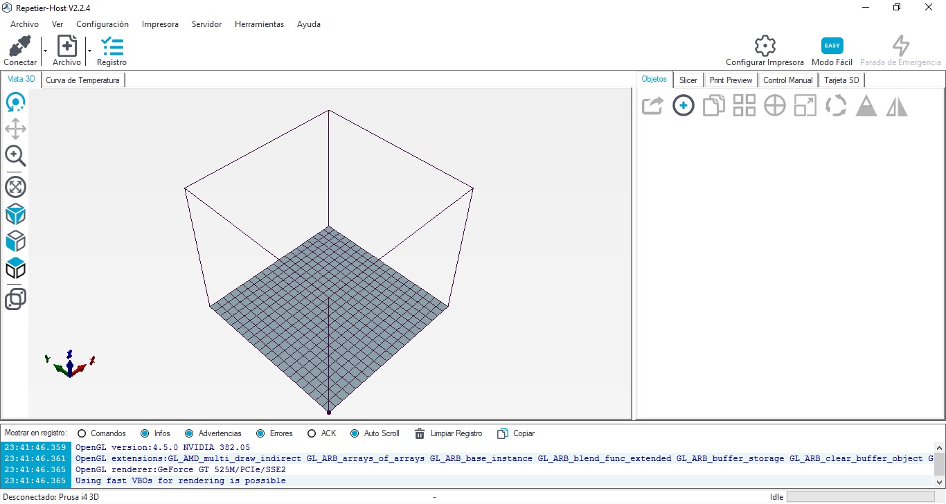
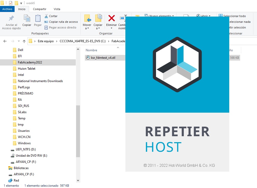
I locate the 3D test file and open it with Repetier Host.
Click Connect.
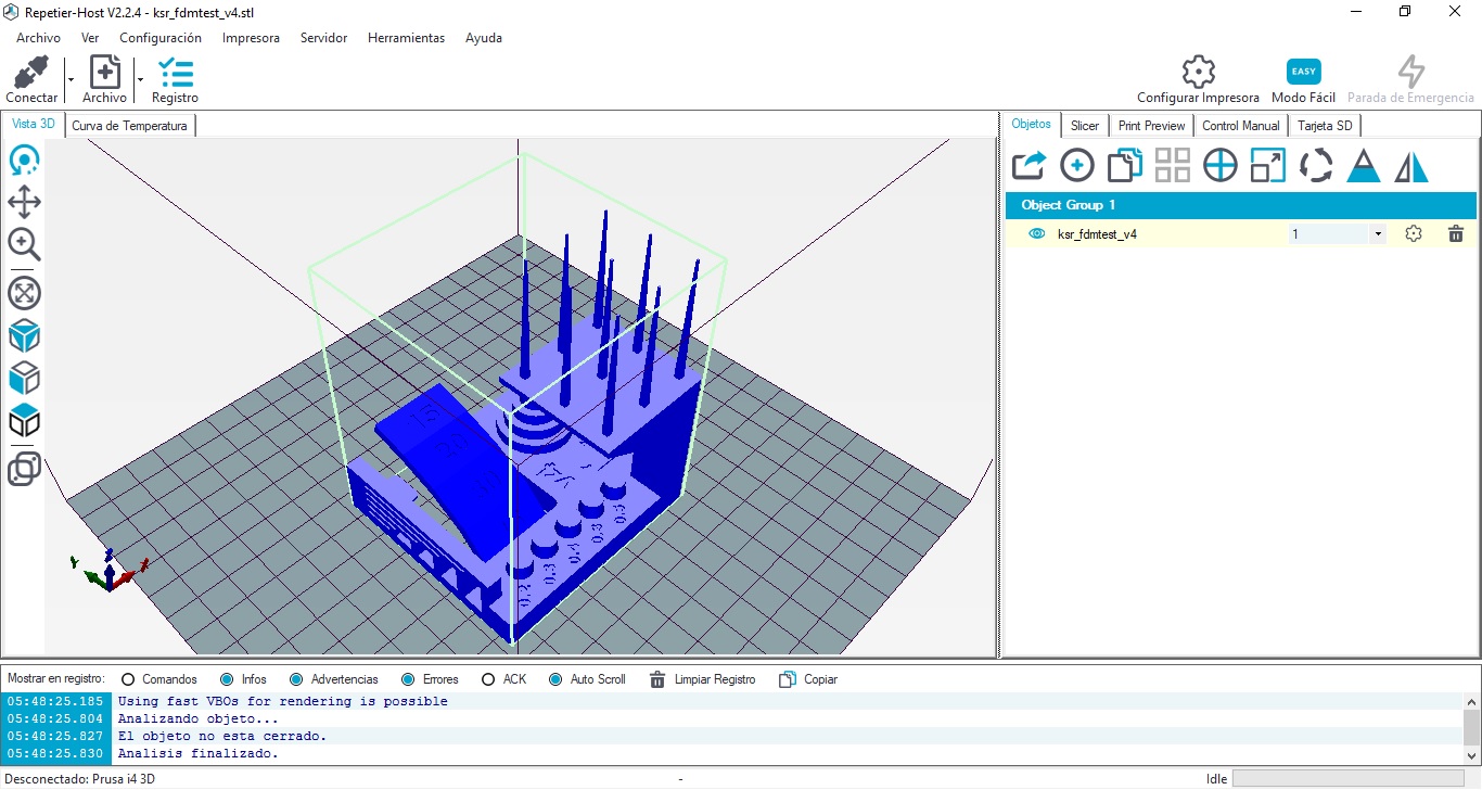
Transfer the Slicer and Print.
Printing the Test File.
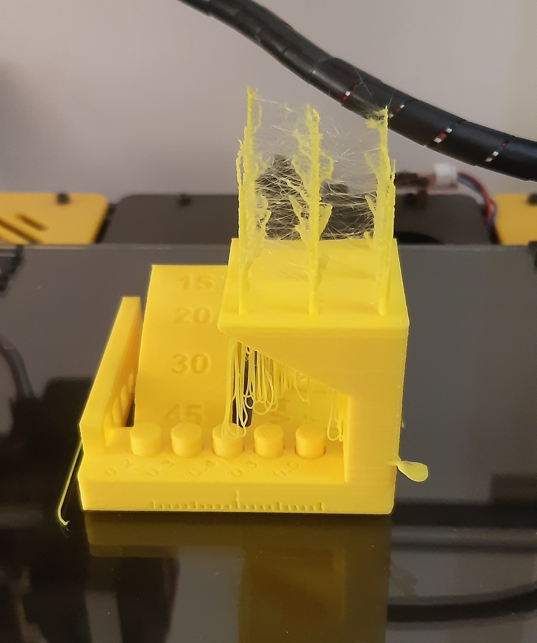
After 4 hours and 25 minutes I finish printing.
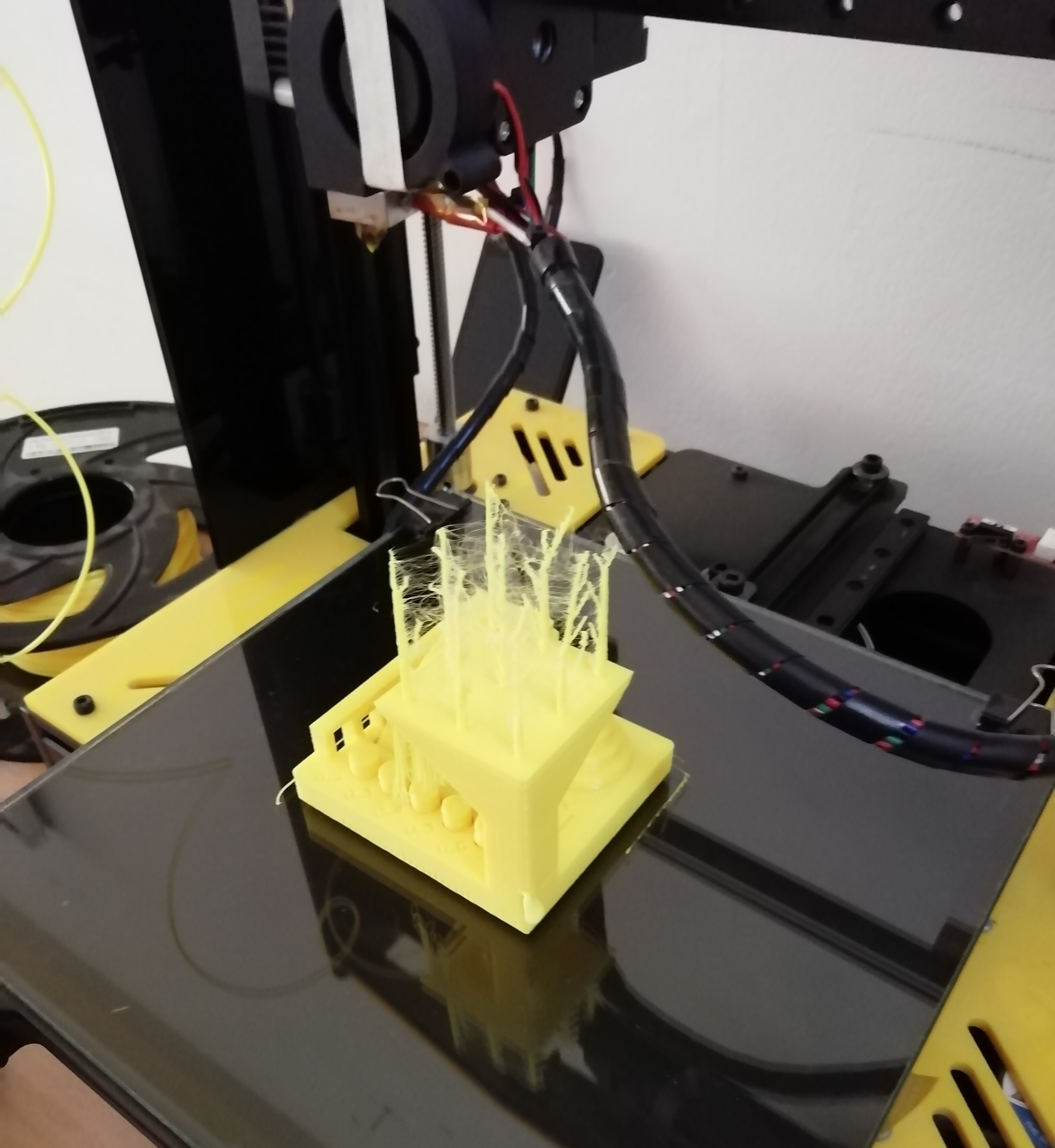
A closer view.
With the vernier we verify that the measurement is 2 cm. with respect to the X axis.
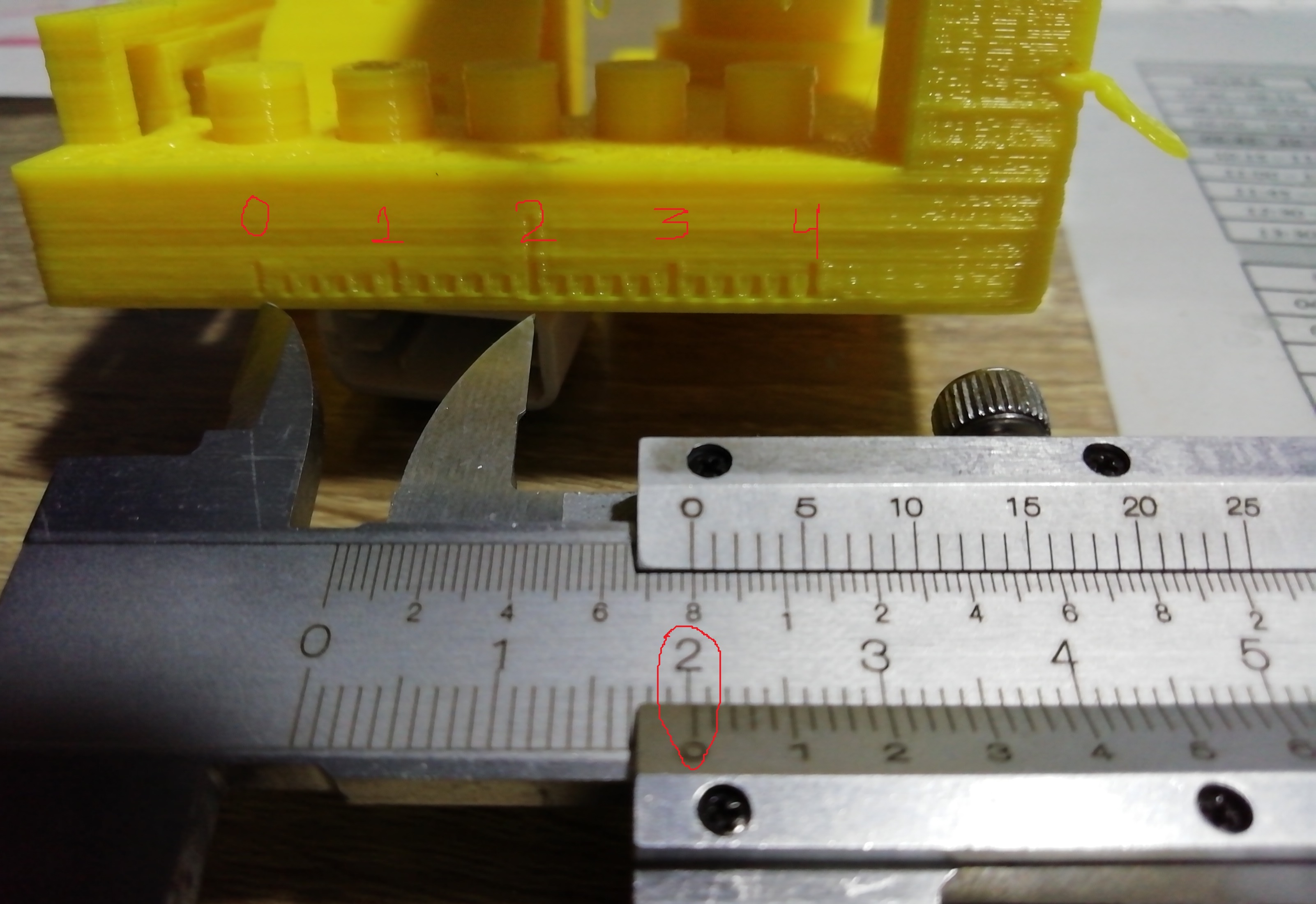
As a team we managed to make the 3D pattern.
Video in progress:
Working individually
1. Design and print a small object of a few cm3 limited by your printer that cannot be manufactured subtractively.
Before starting with the development of this work block, it is necessary to highlight that subtractive manufacturing encompasses several controlled machining and material removal processes. These processes consist that while an object is being shaped, material is removed from them through cutting, drilling or grinding processes. However, when it comes to additive manufacturing, it is quite the opposite, while the object is being shaped, material is added layer by layer, joined together, until the complete piece is obtained. This type of manufacturing is what you get with a 3D printer.
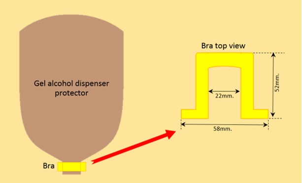
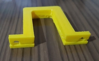
For the 3D printing I considered as an object a holder for the protector of the alcohol gel dispenser. The purpose is demonstrated in the following design.
As a 3D design tool, the Onshape software was used.
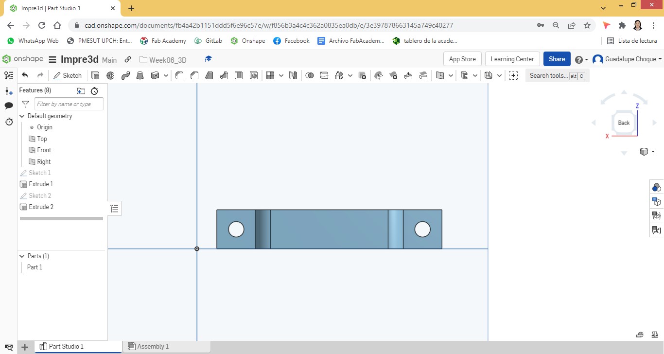
According to the measurements of the dispenser protector and with the use of the software tools we proceeded with the design.
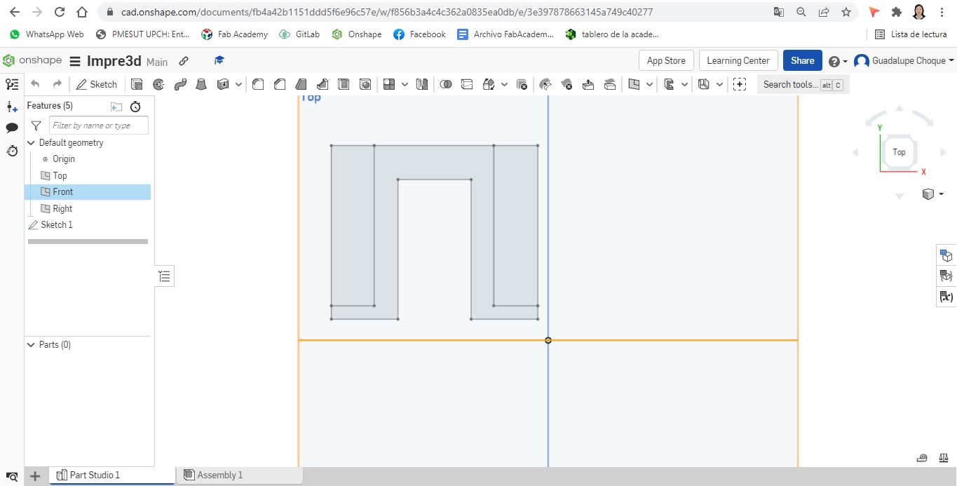
In order to shape the silhouette of the object, the corner rectangle and line tools were initially used.
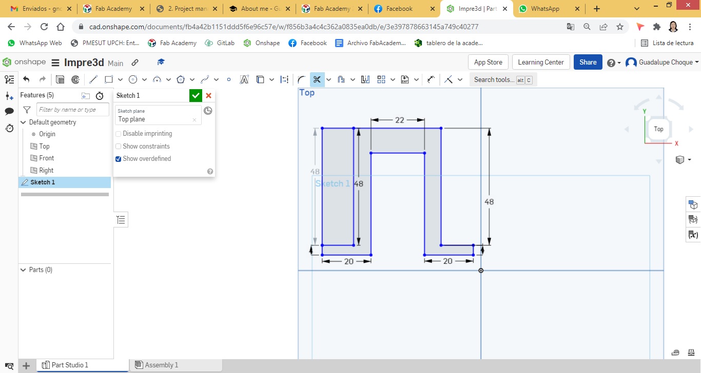
The Trim and Sketch Fillet tools were used for greater precision of the edges of the object.
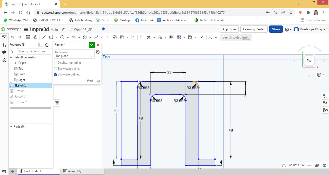
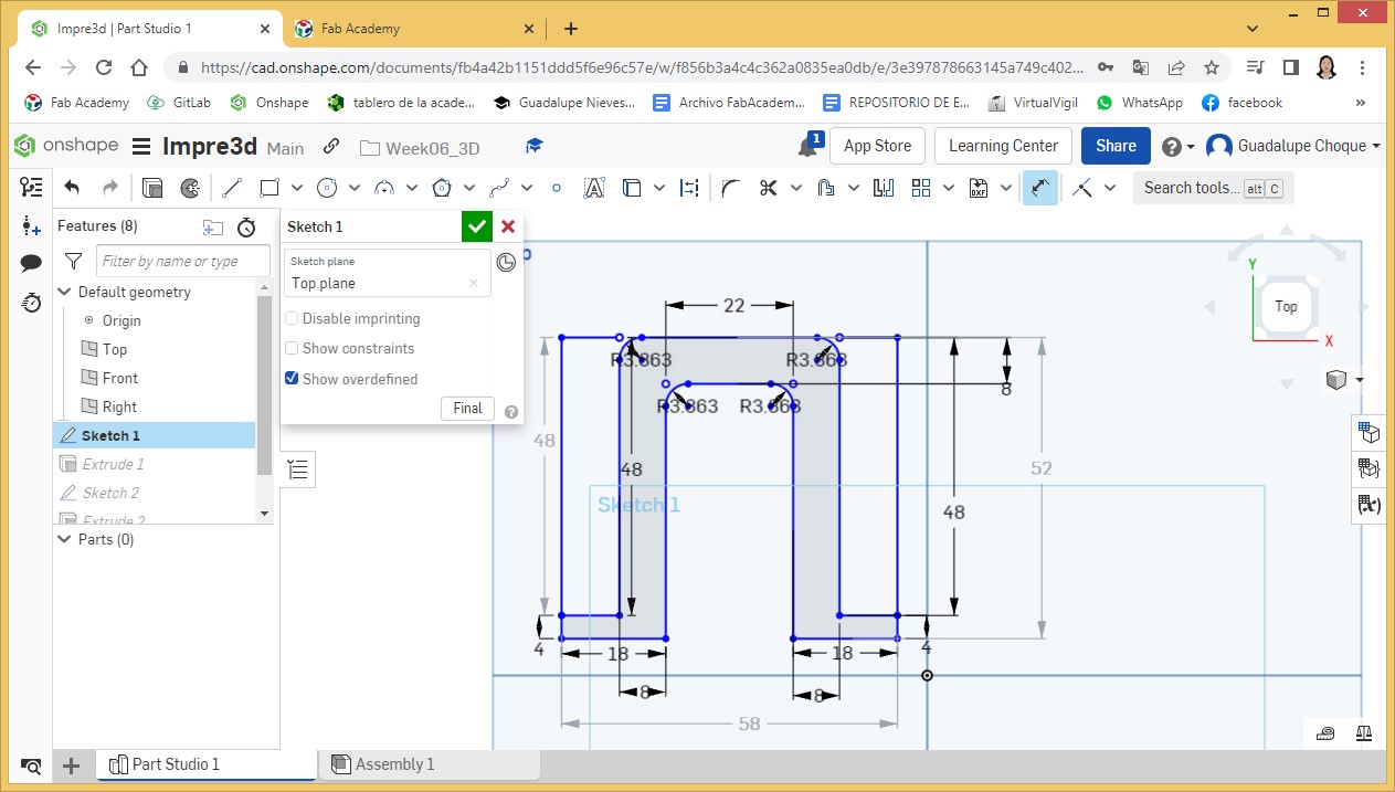
Finishing pointing out the measurements of the object in detail.
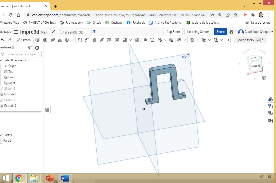
In new sketches, under the Back view, circles were inserted with the Center point circle tool, which would become holes with the Extrude tool.
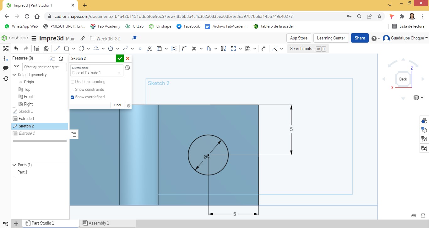
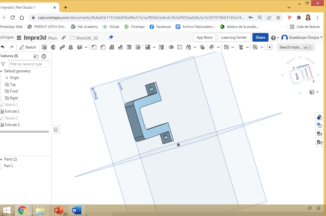
The same procedure was performed for the second hole.
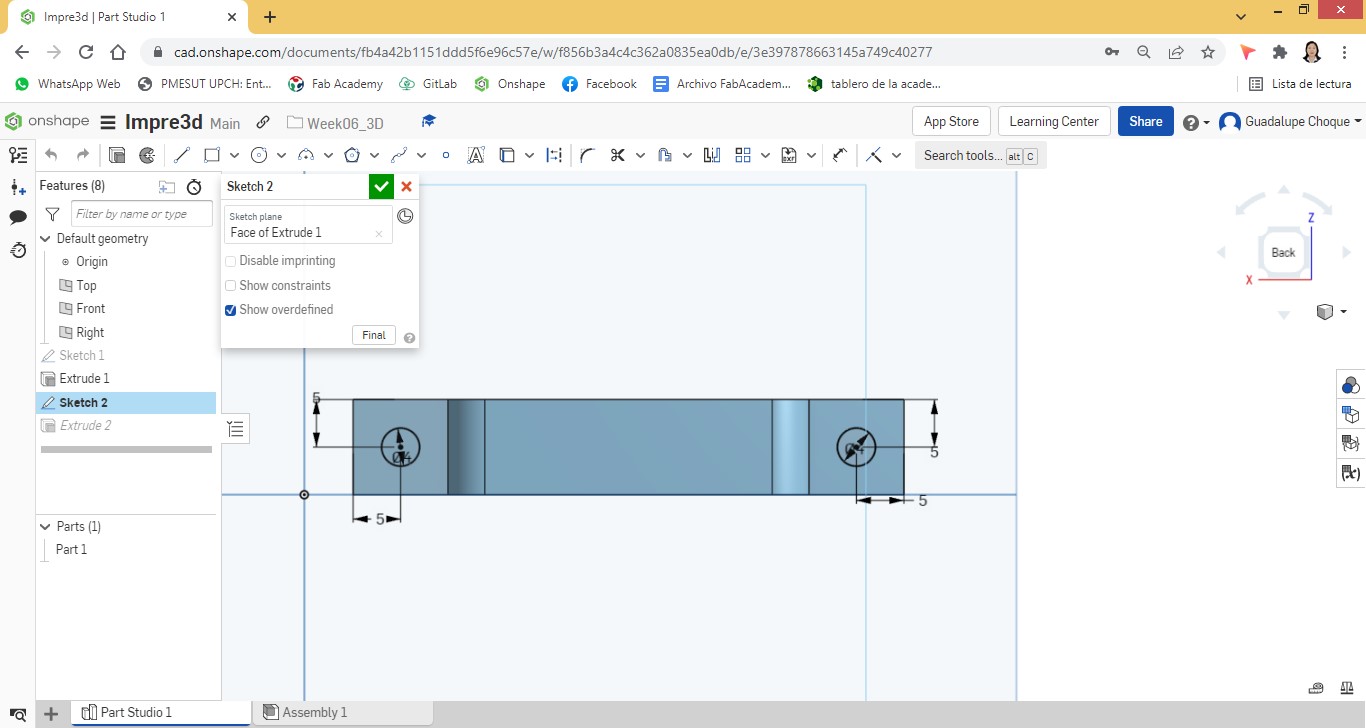
In the same way, selecting the objects that play the role of holes, an extrude was applied.
The view of the fastener from two angles.
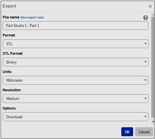
Once the design was completed, it was exported.
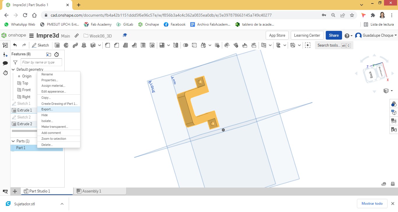
The export of the file was done in *.stl.
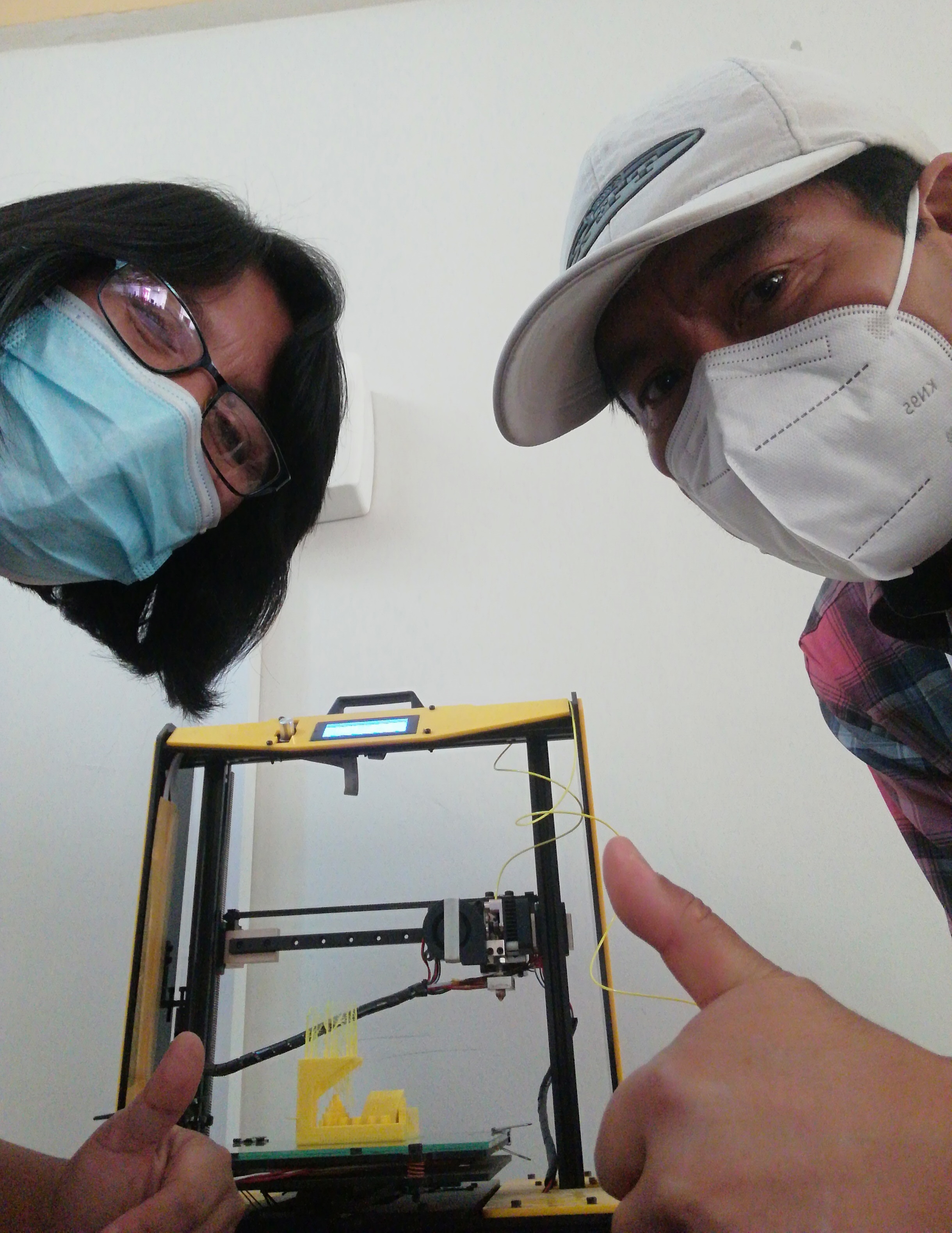
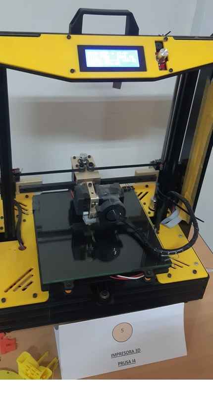
It is a 3D printer, model Prusa I4, in which the printing was made. This printer belongs to the Industrial Electronics Study Program and its Coordinator kindly provided it to us to develop our work.
This is an image that corresponds to the printer in question..
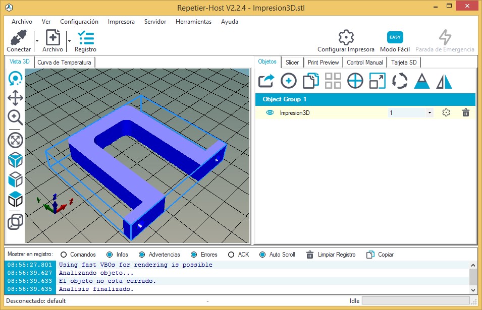
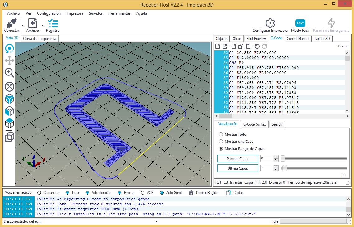
As it is the Repetier Host, the software that manages the 3D printer, that is where I retrieve the *.STL file.
To specify the corresponding settings for printing, I select the gear icon (Printer Setup).
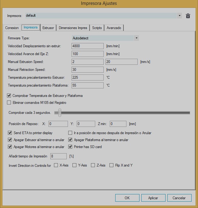
Once the Printer tab is selected, I enter the Extruder Preheating Temperature values; 225°C and Platform preheating temperature; 55°C Then okay.
I select the Slicer tab from the manager.
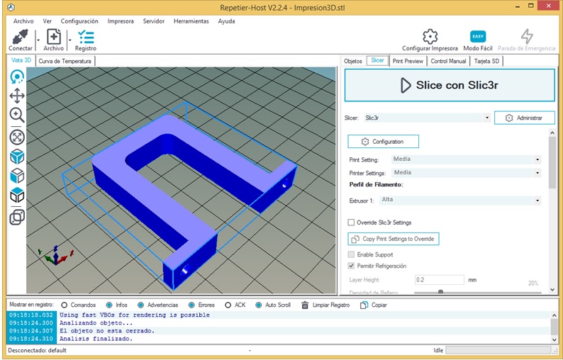
Under Extruder1, I select High. While, Print Setting and Printer Settings, keep the Media values.
Click on Slic3r to convert the 3D image to Gcode.
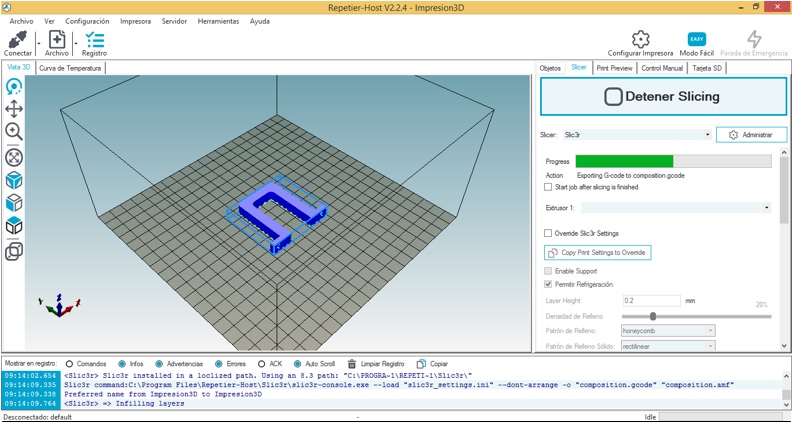
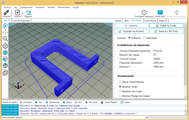
After the conversion, you can know the duration of the object print equal to 37m:8s.
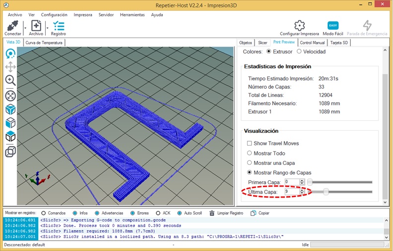
To get a visualization of the printing behavior layer by layer, I activate the Show a layer button and then I manipulate the last layer, through the increment object.
Also, I can see the printing behavior through the Gcode tab. Locating myself in each line of the coordinates generated by the Gcode, I can see the displacement of the machine, it is what the extruder is following.
Going back to the Slicer tab, I click Print.
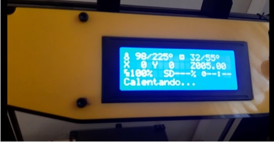
I walk over to the printer and I can see that the printer is heating up.
Once heating is finished, printing starts.
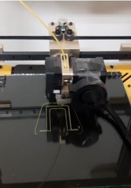
As it is printed layer by layer, the internal filling is shaped.
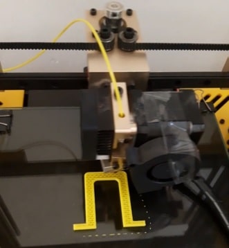
After 37 minutes, the printing of the object is finished.
The piece was removed.
The video below summarizes the bra printing process.
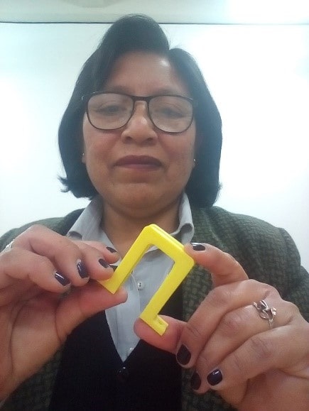
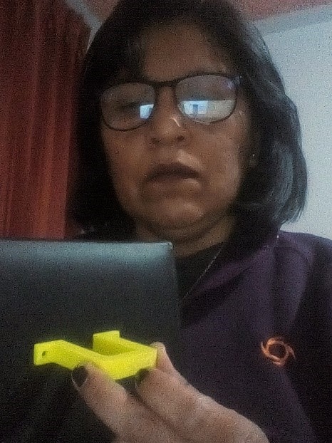
Already with the bra in hands.
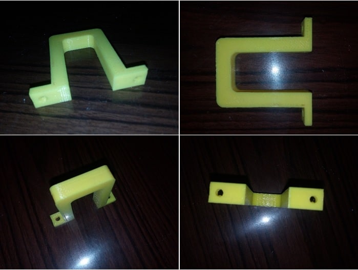
The finish of the printed bra is quite acceptable and you can attest to this through the following photos, taken from different angles.
Comparing measurements between the designed object and the printed one
Checking the external width of the bra, 58mm.
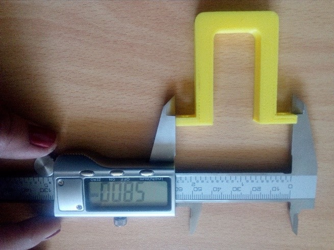
Measuring the height of the object, 52mm.
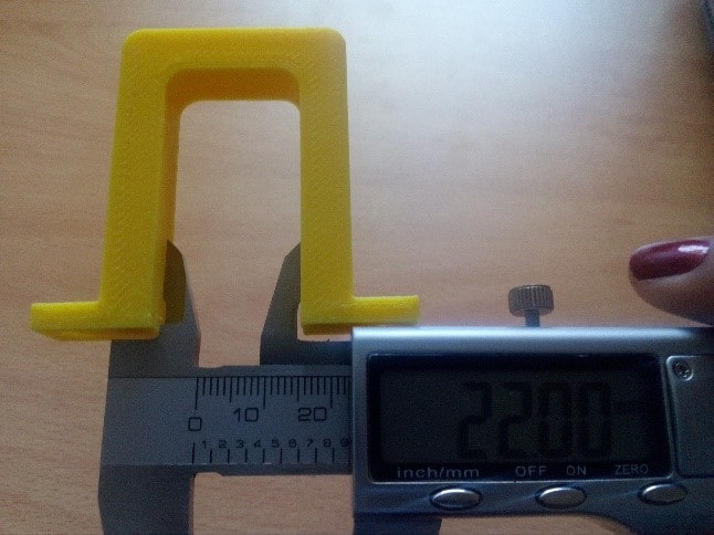
Checking the internal width of the object, 22mm.
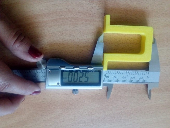
Finally, I proceed to measure the depth of the piece.
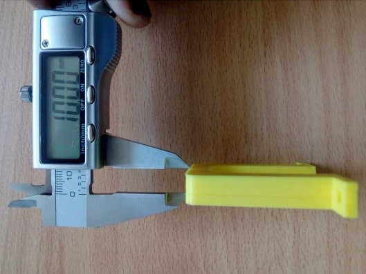
The depth is 10mm.
As has been confirmed, the measurements of the printed bra are exactly the same as those that appear in the design. With this, it is simply possible to affirm that, from a digital design, we obtain a physical object, respecting exactly the same measurements. But, we can also handle low-scale measurements. All according to user preferences.
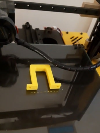
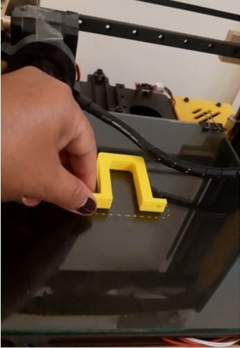
As pointed out at the beginning of this work, the idea of the printed object is to act as a holder for the protector of the alcohol gel dispenser. This will be located in the nozzle of the protector, positioned vertically and will be held with the help of two screws inserted into their holes.
Bugs and problems presented
While the first print of the bra was being made, the filament broke. My reaction in putting the filament back in was delayed, which caused the print to be spoiled.
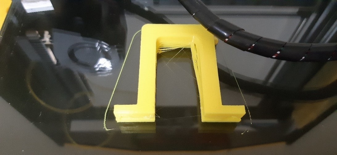
Despite resuming printing, while it was printing, evidence of the problem could already be noticed, threads hanging.
After printing, the object is displayed vertically, from above.
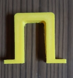
Positioned horizontally, with a view from above.
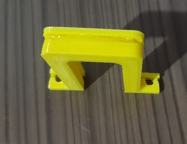
The object with a horizontal position and a tilted view.
The good thing is that these errors could be corrected, as demonstrated above. And the best of the best is that making mistakes has strengthened my learning. Good for it!!!
2. Scan into 3D object and optionally print it
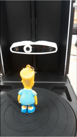
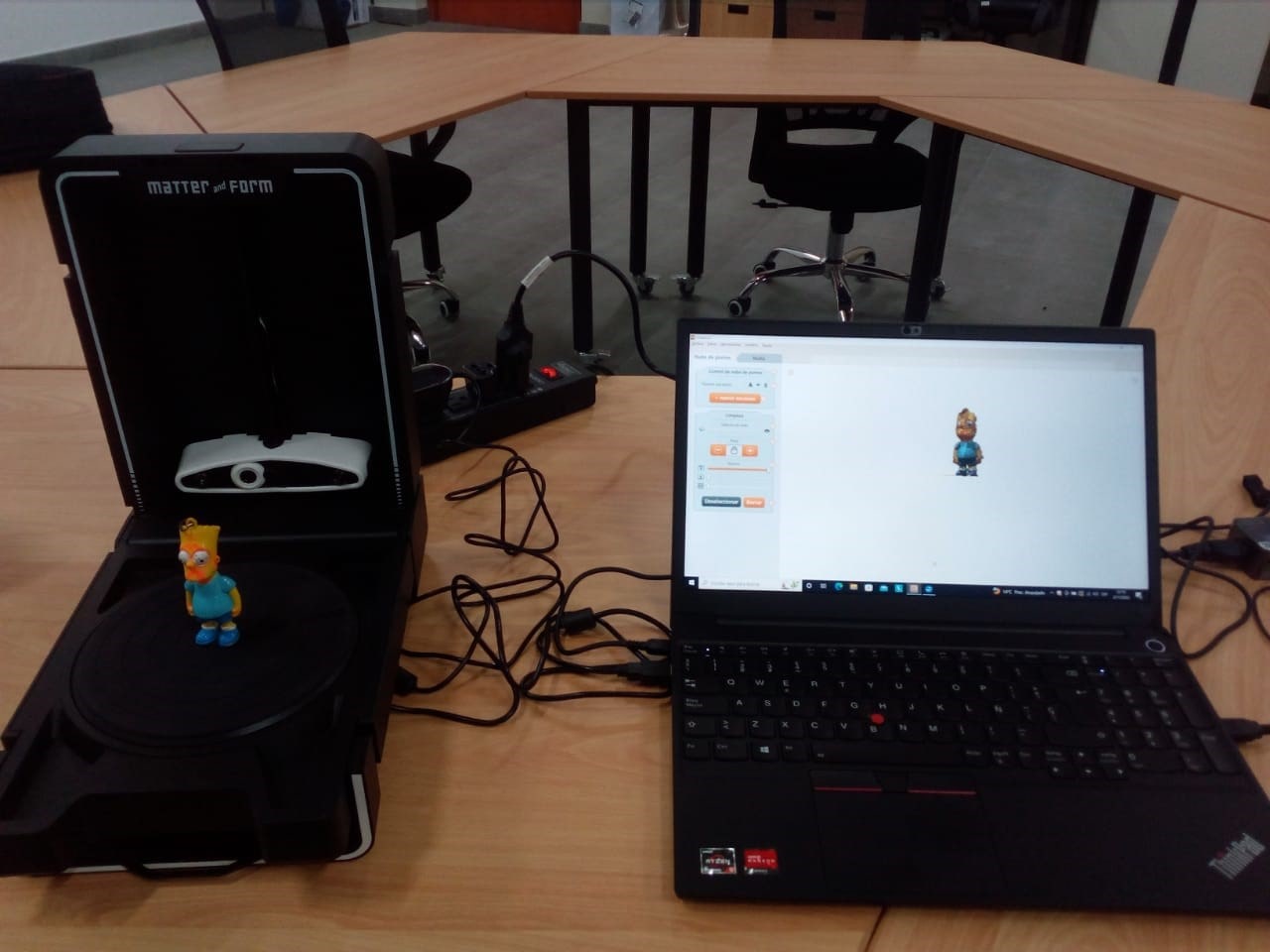
In our lab we have a portable and affordable desktop 3D scanner, brand Matter and Form (V2).
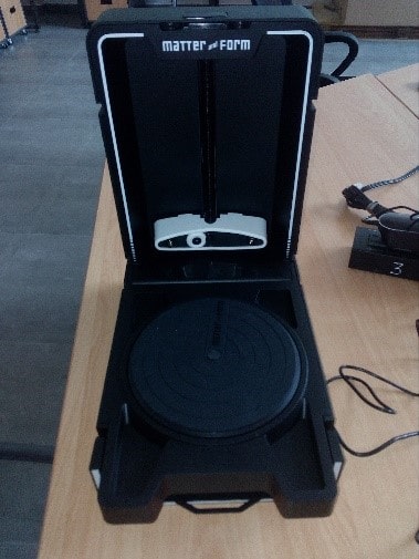
The objects that can be scanned by this equipment must have a maximum height of 25 cm, a diameter of 18 cm. and a weight of 3.0 kg.
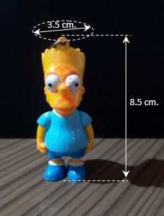
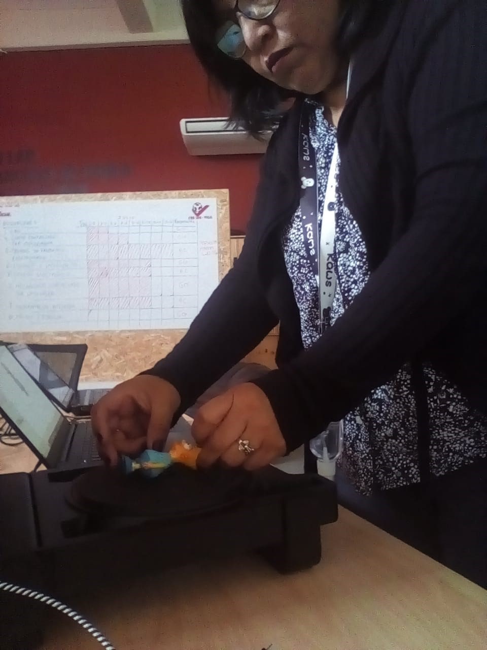
Taking into account the maximum dimensions of an object accepted by the scanner, a Simpson doll was selected, with a height of 8.5cm and a diameter of 3.5cm. and a weight of 40 gr.
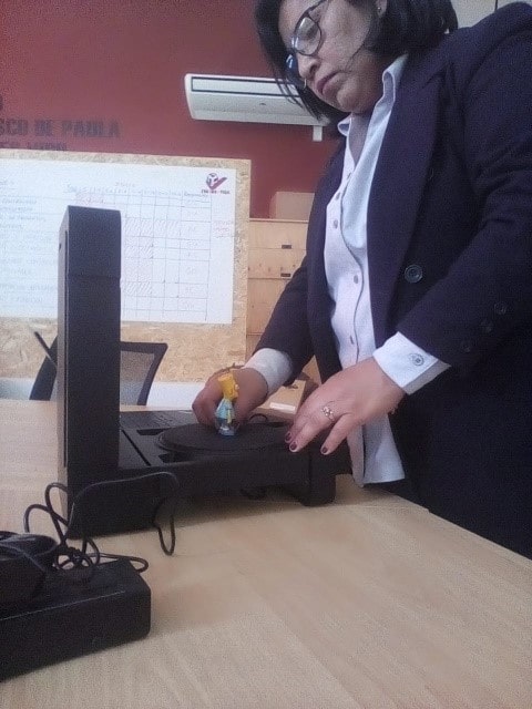
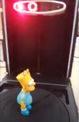
Connected the scanner to the laptop and both turned on, the doll was placed in the center of the scanner's turntable.
To manage and control scan settings for good results, MFStudio software has been loaded.
To start working on a new scan, click New Project.
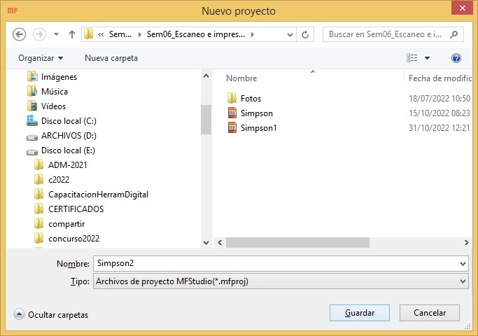
Enter the corresponding name and Save.
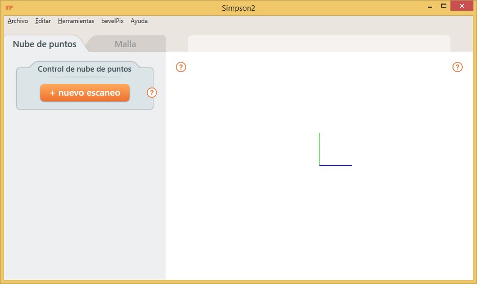
Click New Scan to customize the scanning process.
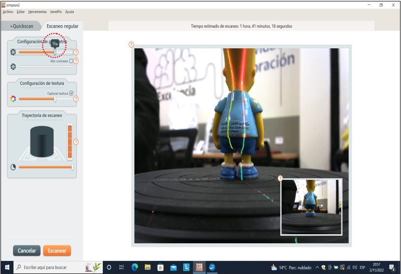
It was possible to notice the appearance of two vertical lines, which represent the two lasers that would capture the geometry of the object. The appearance of noise in the lasers suggested that the quality of the scan was not going to be very good, so I proceeded to configure it. For this I activated the Regular tab and moved the squeegee until both vertical lines had as little noise as possible. This was achieved when the puller was dragged to 1/32.

In the same way, it was done with the squeegee that would define the optimal color of the scan; 1/16. Procedure executed in Texture Settings.
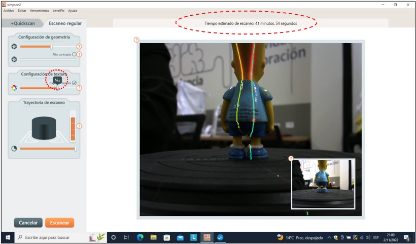
Move vertical slider sets how high the camera head will move. We reduce only one block to ensure that the largest number of points of the object will be scanned.
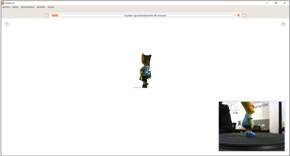
As can be seen in the image, the scanning time would be 41 minutes 54 seconds. If I deactivate the Capture texture box, the time is reduced, but the image of the object would be hidden. I preferred to leave it activated.
Once I was done with the scan setup, I clicked Scan to start the doll scan.
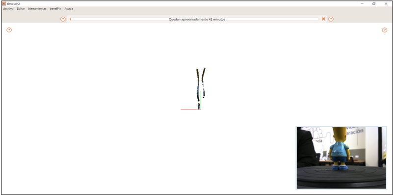
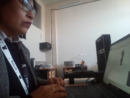
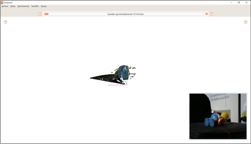
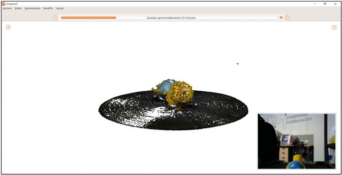
Once the scan has started, it can be seen that while the turntable, on which the doll is located, begins to rotate clockwise, the lasers pass through the lenses of the scanner head pointing towards the object. Part of the scanned object is displayed on the screen.
At certain times the scanner head moves vertically upwards.
The object almost has the shape of the doll.
After the estimated time has elapsed, the entire object can be seen on the screen.
Scanning was completed.
Showing the end result.
It can be clearly seen that the feet of the doll have not been well scanned, they are not complete. So a second scan is necessary.
For a second scan, the doll must be placed in a different position than before. I laid him down, facing up, with his feet facing the scanner head.
I click the New Scan button and repeat the geometry, texture, and scan path setup steps.
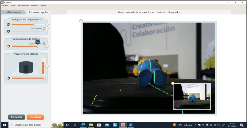
The estimated scanning time is 1 hour. 11 minutes 36 sec.
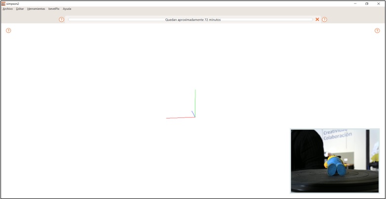
The scanning procedure is repeated.
Continuing with the scan.
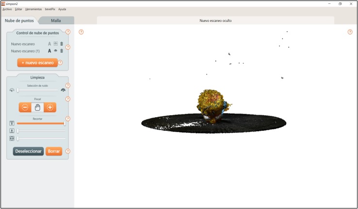
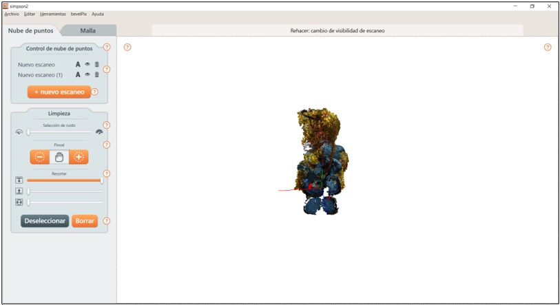
Once the second scan is finished, it is displayed at the same time as the first scan, as can be seen in the following image.
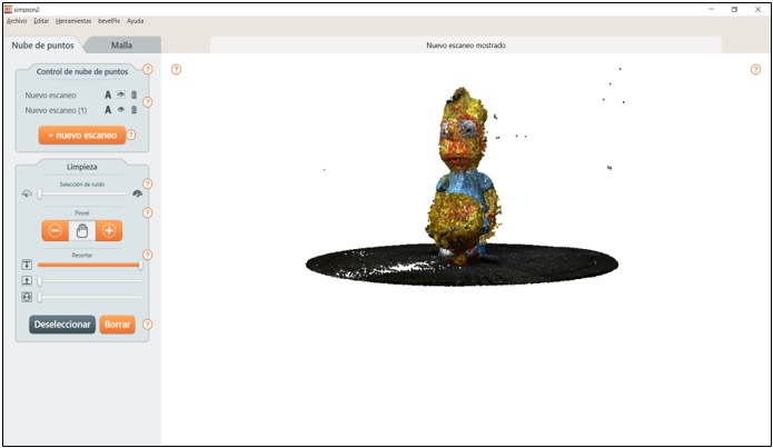
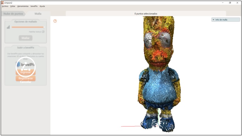
To be able to work on them independently, to eliminate existing noises, I hide the corresponding part in Point Cloud Control.
I started by cleaning up the noise from the first scan, so I hid the second one.
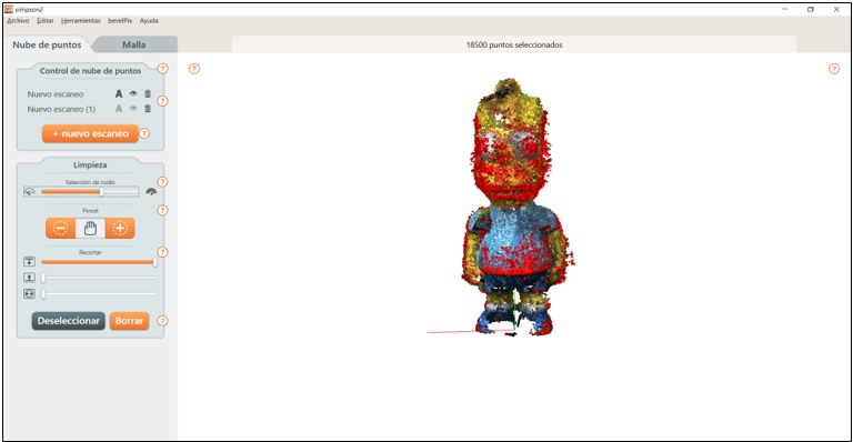
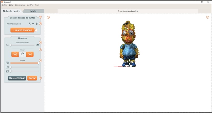
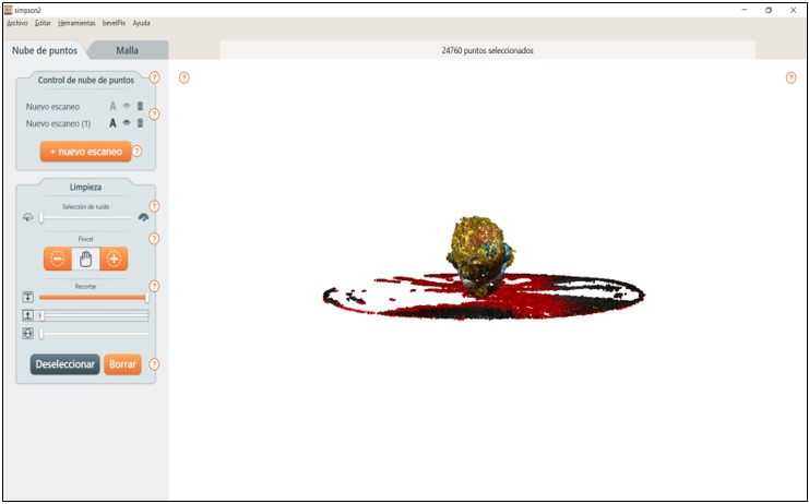
To remove the noise, I went to the Cleanup area and dragged the Noise Selection handle until the existing noise in the scanned object was highlighted in red. Then I select Delete to remove the highlight.
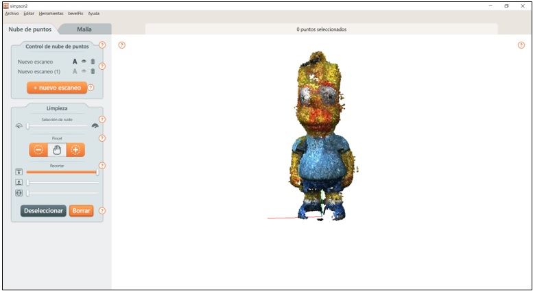
The scanned object takes on a better appearance.
To remove noise from the second scan, I hid the first.
I proceed to remove the noise using the brush and then click Delete.
I improve the cleanup, using the Noise Selection puller and deleting it.
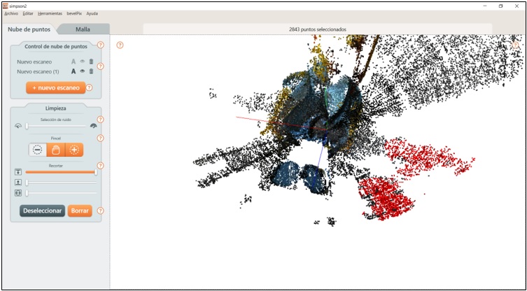
I rotated the object for a better location of the noises and proceeded to eliminate them. The object was better defined, although incomplete. But, it was possible to notice that the part of the doll's feet were better scanned.
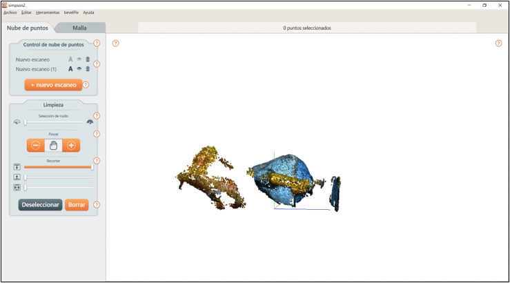
Once the noises of the scan were eliminated, I proceeded to align them and then combine them. To achieve this goal, first of all, I had to visualize both scans and try to place them in the same position.
Then I selected Align to achieve the combination of both parts.
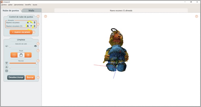
IIt turned out much better, the doll's feet are now complete, but there was still noise, so I proceeded to remove them. For a better location of the noise, I saw it convenient to enlarge the view.
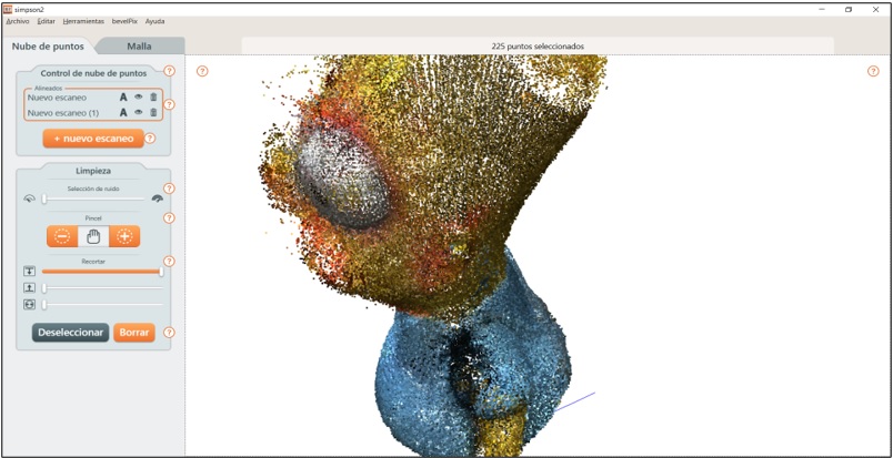
And with the help of a brush I eliminated the useless.
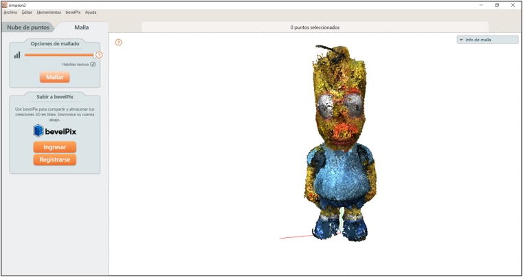
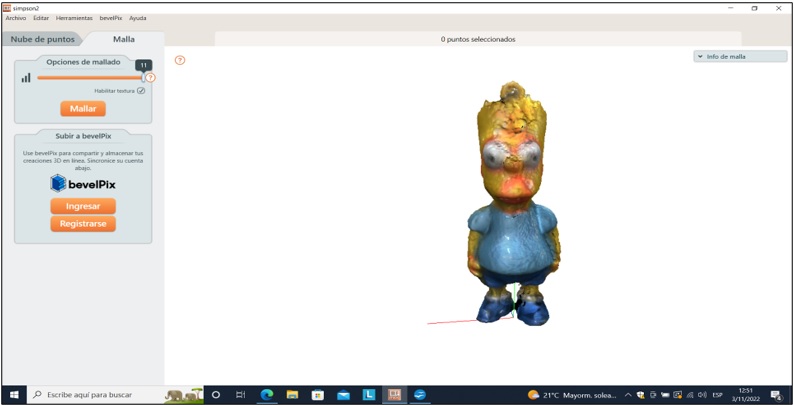
Much better, the only thing left is to mesh it. For this I dragged the Mesh Options slider to the maximum and then clicked Mesh.
Done, it turned out pretty good!
Now to finish we export the file in STL.
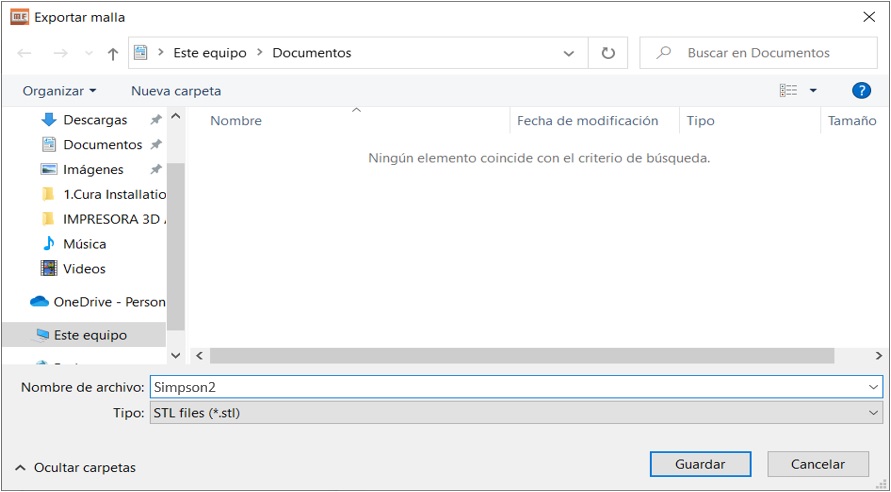
Ready to work it in 3D printing.
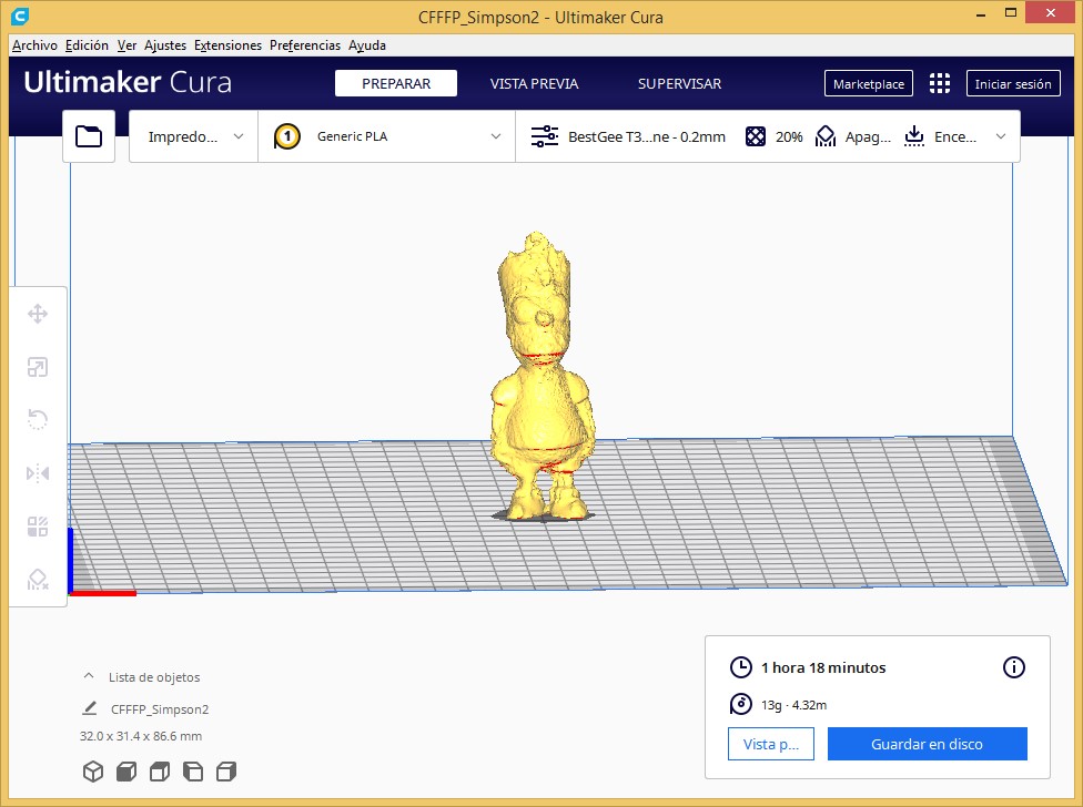
Acceptable!!!!
Natives files
| Ord | Description | Files |
|---|---|---|
| 1 | Pattern | ksr_fdmtest_v4.stl |
| 2 | 3D Bra | Impresion3D.stl |
| 3 | 3D Simpson | Simpson2.stl |