Final Project
This page is a documentation of my final project in Fab Academy 2022.
My Presentation
Poster
Video
Final Project Proposal
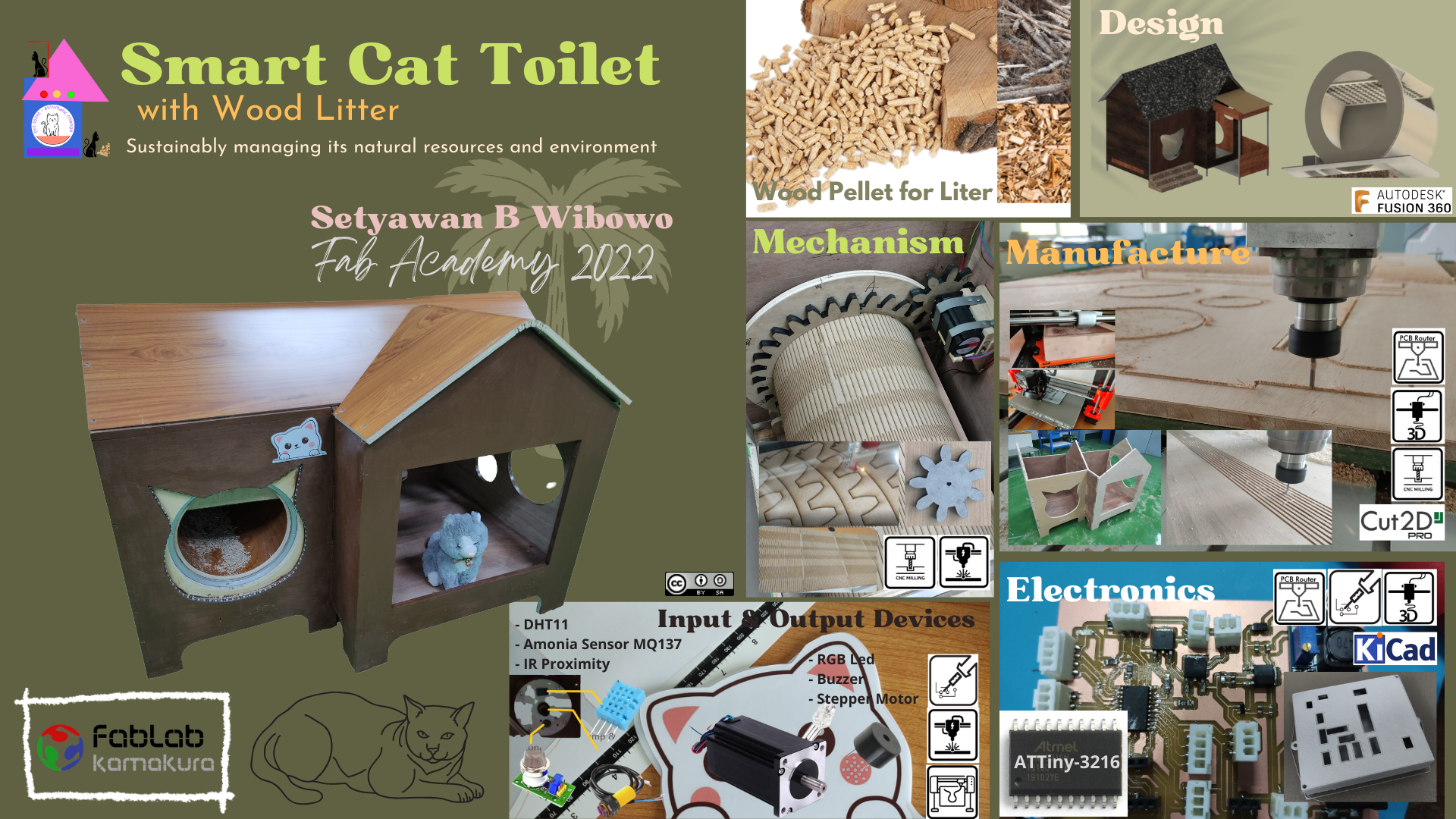
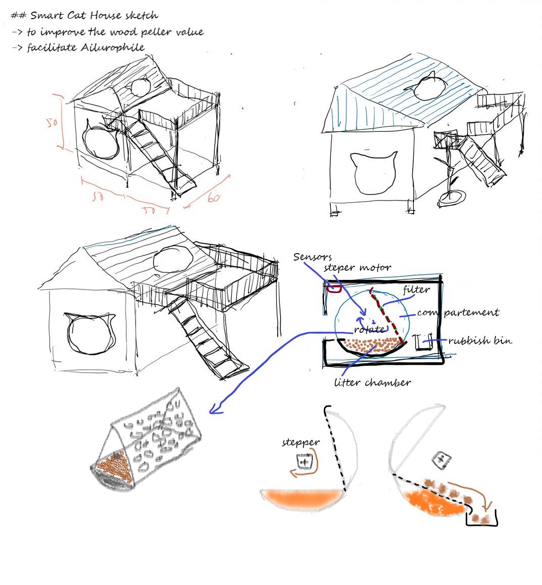
I have a plan to make a final project, namely: Smart Cat Toilet (House)
Background
There is a lot of wood waste in Indonesia, currently it is only used for fuel (biomass) by making wood pellets. I feel the need to increase the value of wood pellets, one of which is using wood pellets for pet litter. Meanwhile, there is currently a project on my campus to make smart agriculture. And lots of cat lovers too, with more and more pet shops popping up. I want to combine the use of wood waste, animal lovers and smart agriculture. So that this project will be able to utilize wood waste, help animal lovers who are environmentally friendly and can be used for plant fertilizer.
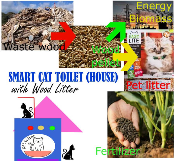
This machine can be used for cat lovers. Utilizing wood waste so that it does not just become carbon (for burning), even the economic value of wood waste can increase. The resulting manure can be used as plant fertilizer so it is environmentally friendly.
Machine Concept
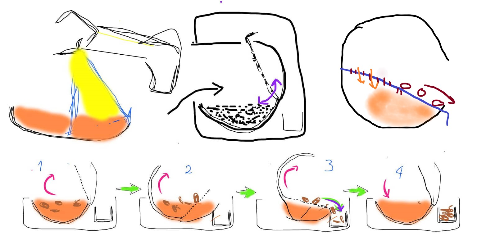
This machine is a toilet that will automatically change litter after the cat has defecated and is equipped with a cat play area. In the toilet section there will be a chamber containing wood pellet litter as a place to pee for cats because of the nature of wood pellets as an absorber of liquids and odors.
When the cat enters, it will be detected by the PIR (Passive Infrared Receiver) sensor. After the cat leaves the toilet, the chamber will rotate and separate the cat’s poops from good wood pellets.
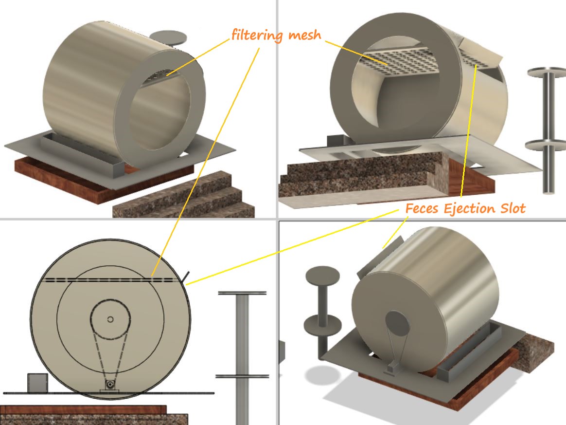
When the cylindrical drum rotates, wood litter and cat poo will also rotate. I use the mesh to filter and separate the dirt from the wood litter. Small pellets fall through the “filtering mesh” but the poop is too big and will fall out the “Ejection Slot” and rolling falls into the trash tray
In addition, a monitoring function on the quality of the environment in the toilet will also be provided. There are several sensors installed such as temperature, humidity, odor sensors (ammonia). If the conditions in the environment in the toilet or the condition of the wood pellets are not good, the wood pellet will be replaced.
The materials used are mostly from plywood. The chamber material in the toilet will be made using a 3D printer and laser cutting. The chamber pellet rotary mechanism uses a dc motor with a fairly strong torque. There are several sensors and monitoring/indicator devices that will be installed. Equipment details will be explained in each section below.
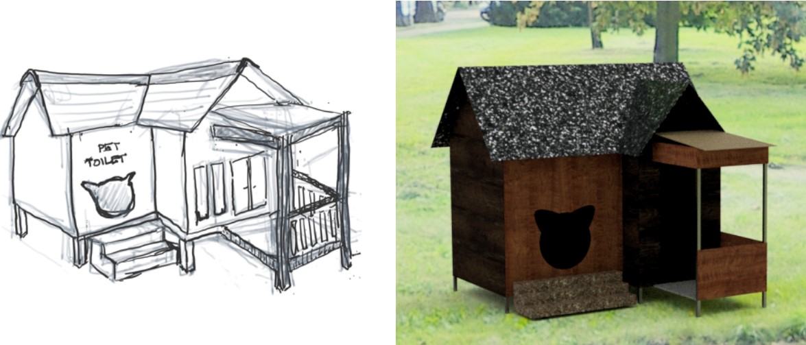
2D and 3D Modeling
The first step after I understand the concept and how the machine works, I need to detail the design scheme of the tool.
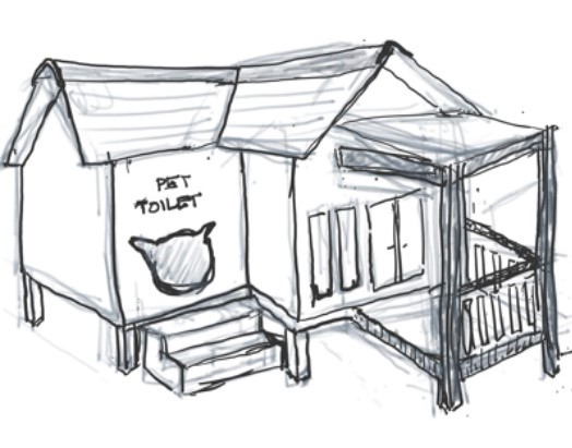
There is an interesting suggestion from the instructor if the concept of the house form follows the shape of a traditional house in Indonesia.
My 2D design created a logo using Inkscape. here’s my picture
![]()
and also make stickers about “Cat Lovers” designed using Inkscape

The results of the sticker making can be seen here
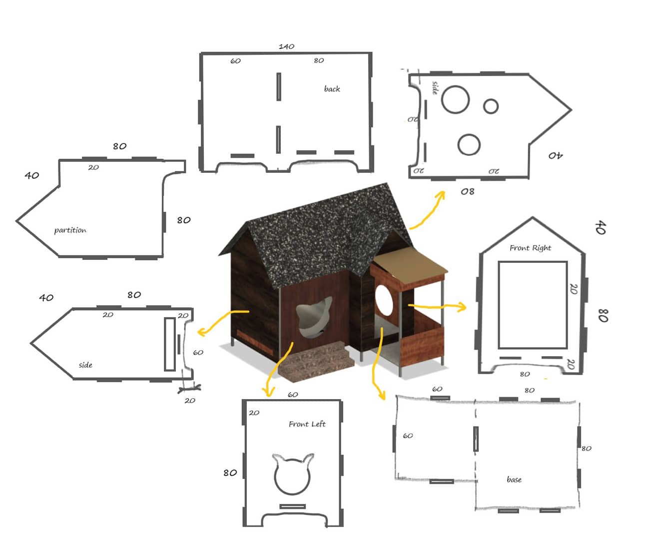
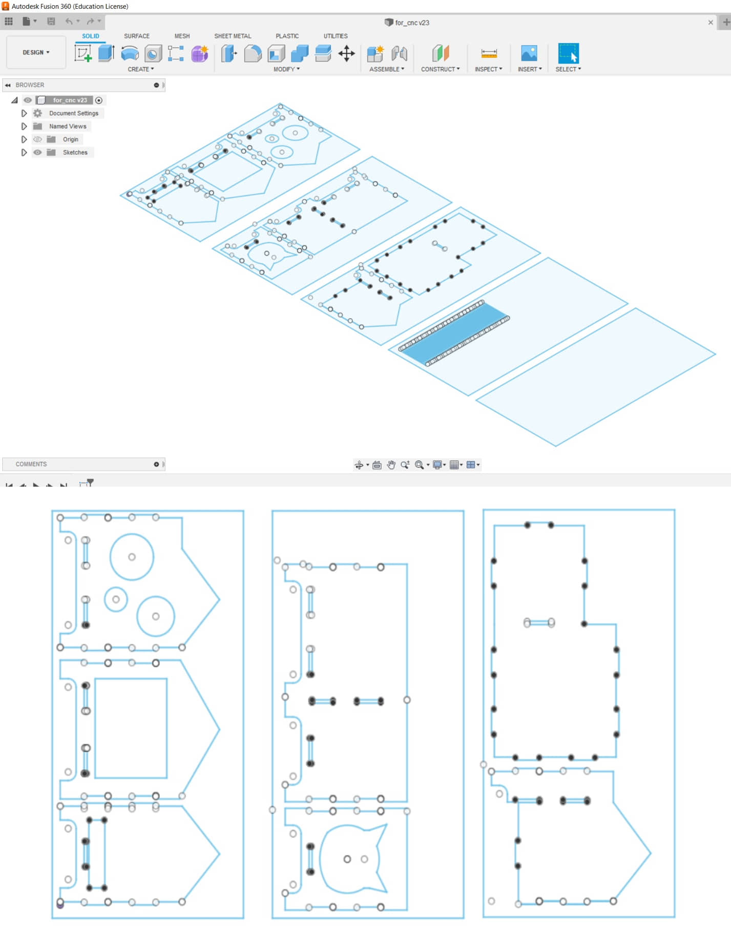
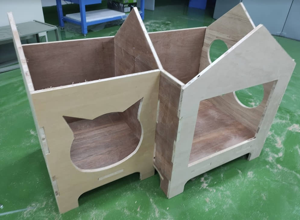
3D design using Fusion 360. starting from drawing the shape of the toilet (house) like the sketch made. In drawing the shape of the toilet (house) still pay attention to the construction system, so that a wooden pillar frame is also installed as a building framework.
In this 3D design, a building will be designed that contains two main rooms. One as a toilet and one as a play area. The toilet is in the form of a room containing litter (wood pellets) and the room will be able to automatically clean if a cat has defecated. The size of the toilet is about 60 cm x 60 cm x 80 cm with a room in the form of a drum that has a automatic fecal filtering system.
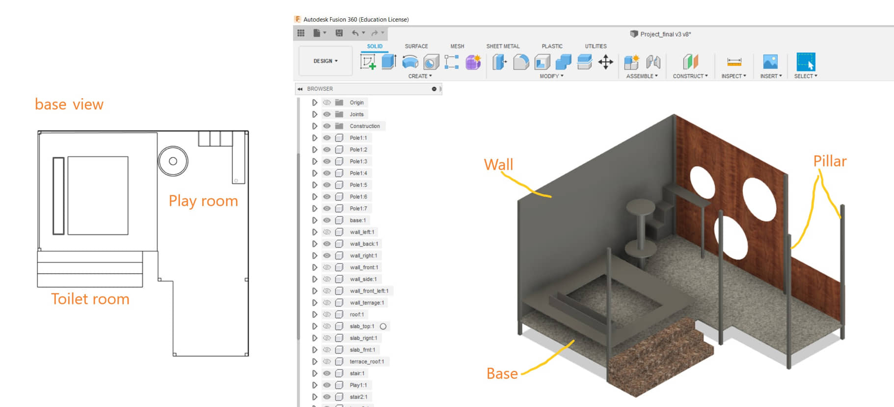
While the other part of the room is a playground for cats. The size of the playground is about 80 cm x 80cm x 80 cm
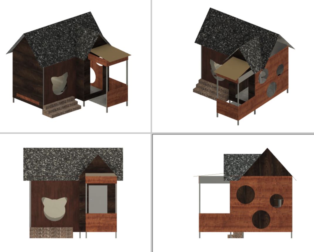
House (toilet) view to be
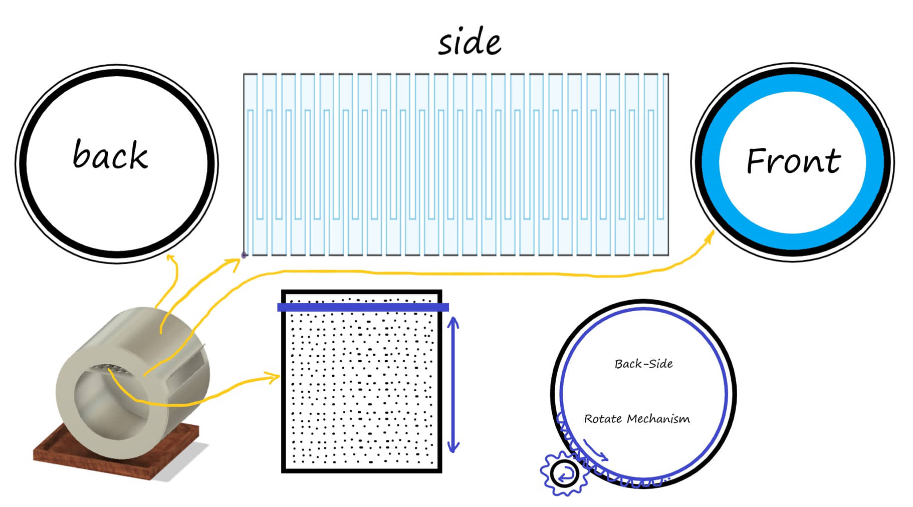
Inside the toilet there will be a chamber (cylinder) that will function as an automatic pellet replacement mechanism.
The separation mechanism is carried out after the cat has defecated. The separation mechanism is carried out by rotating the drum so that the litter will move to follow the rotation of the drum. At the top of the drum there is a mesh that will filter the litter into the temporary storage chamber. Meanwhile, the feces will continue to roll and enter the trash tray.
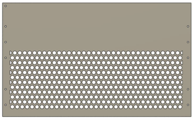
Round filter shape damn fills half of the filter board. The size of the filter is adjusted to the size of the wood pellet to be used. In this case the hole diameter is 10mm.
The form of 3D images in fusion can be seen in the following image
Mechanical System
House/Box wall sketch
#Update for 2D wall design for Milling
Design wall constructions
From the design that has been obtained by the 3D model, I export the sketch in dxf form. This file can be directly exported to CAM Cut 2D Pro software or if necessary editing can be done again on Fusion. (re-import the dxf file and edit the sketch only. Editing is needed to modify the sketch image, especially the joint location and the Kerf effect. After everything was designed correctly, I returned to exporting the sketch in dxf to read on CAM Cut 2D pro.
Note
When making the initial design in the form of a 3D design, so that it can be assembled easily and the dimensions can be checked for correctness when all walls are installed. In this design, the kerf effect is still not considered due to the cutting and joining forms between boards. So I need to edit the sketch (dxf) from export 3D model
Example of the editing I did:
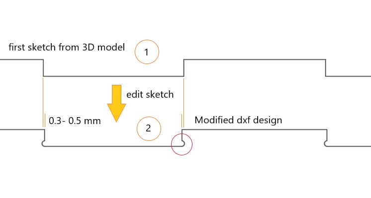
The results of editing I get a sketch which I then export to dxf again to be read on the CAM software
Design for CAM
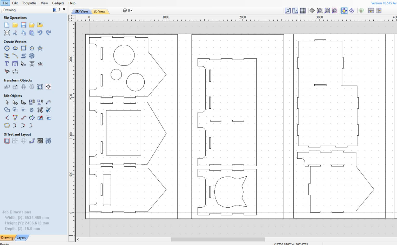
Cut 2D Pro is a CAM software to generate tollpaths in G Code. Details on how to use this software can be found in Week 7. Computer controlled machining
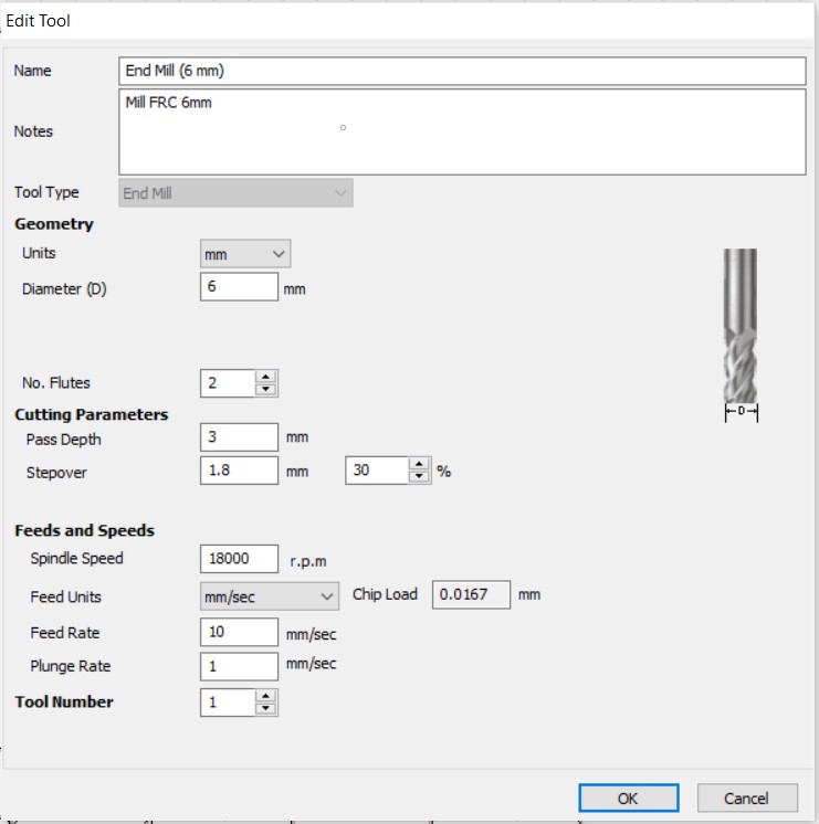
The vector image that has been created by Fusion 360m and exported in dxf form is imported into the CAM Cut 2D Pro software. To facilitate the operation of the CAM, the image has been prepared in a cut position according to the size of the provided board. I used a wooden board (plywood) with a thickness of 18mm. To design the toolpath I used an endmill with a size of 6mm.
A wide portion of the CAM process is cutting plywood to make the walls of the house.
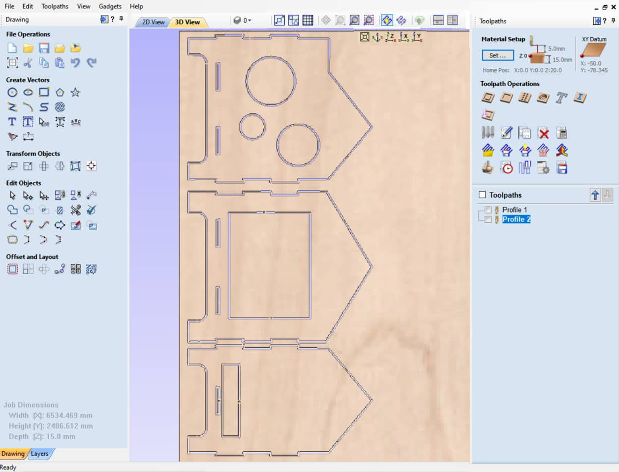
The tool used is an endmill with a diameter of 6mm. The cutting configuration is carried out at a speed of 18000 rpm, a feedrate of 10 mm/s.
After the CAM processing is ready, the cam software will generate the toolpath in G-Code using the General processor. save the file of G code to the drive.
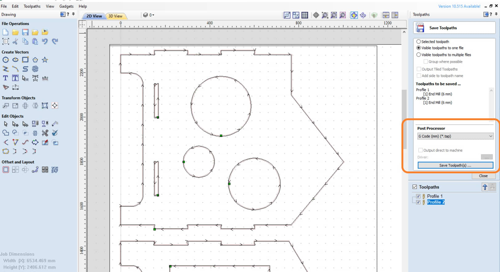
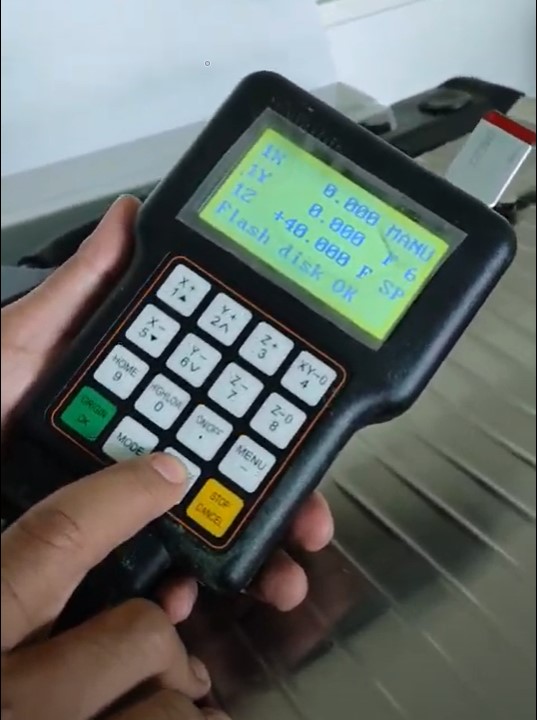
Then the G Code is then copied to the Flashdisk to be run on a handheld CNC router machine.
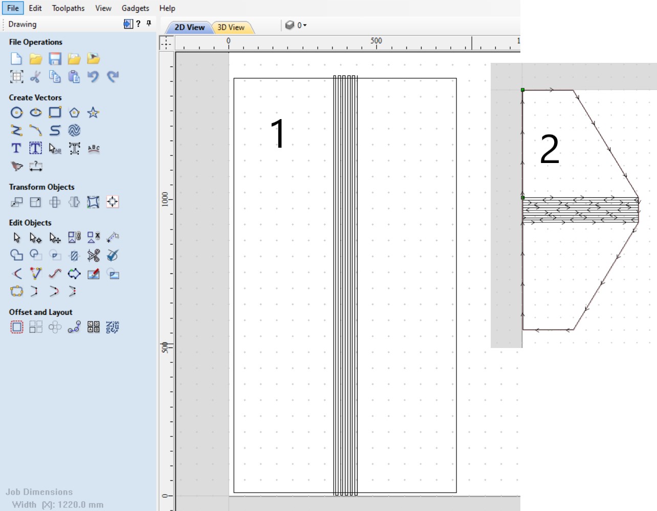
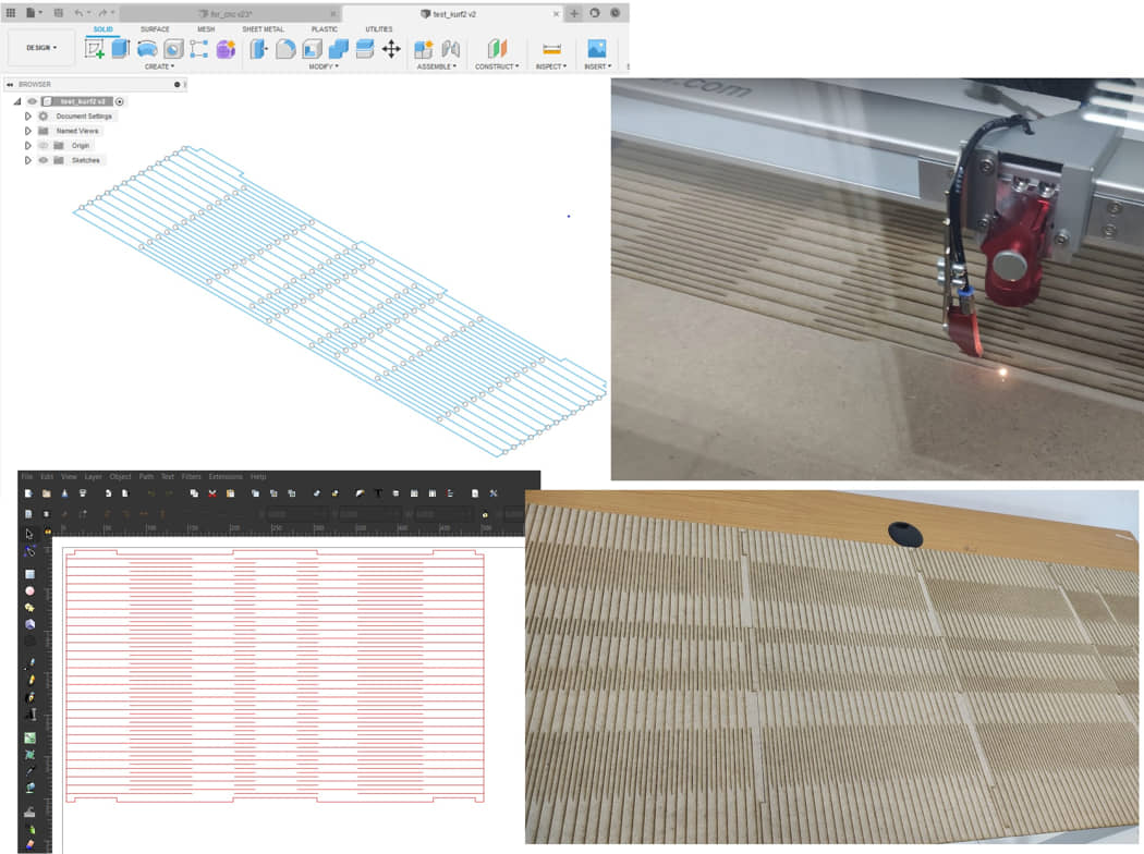
For the roof I designed directly from the CAM software. because I will fold the center of the roof so I use the kerf-bending method to make the roof. The plywood used is 15mm thick with slots used for kerf bending using cnc milling with an endmill tool of 4mm diameter. The distance between the slots is 4mm with a depth of 10mm
#Manufacture Processing
Milling process
The next process is the manufacturing process for milling for plywood. The G-Code that has been generated is then run on a CNC milling machine. As planned in the CAM endmill used a diameter of 6mm.
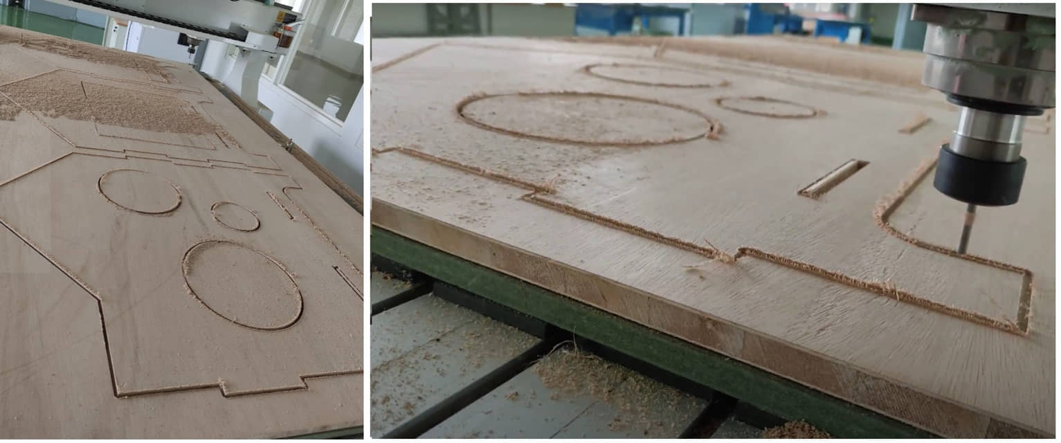
the milling process has been successfully carried out with the cutting configuration as in the CAM setting. the time required for each board is about 15-20 minutes. The whole milling design requires 3 boards. So that the total milling process is about 60 minutes.
Vinyl Cutting
For the purposes of the dashboard display I used a cat’s head display which I gave a sticker made with a vinyl cutter. The manufacturing process is after the head image design is printed on vinyl paper and then scanned using a vinyl cutter machine and cut according to the outline of the outer image.
Assembling the box
After all the walls are milled, the resulting boards can be assembled. I still need to add for the roof. Especially for the roof, there is a kerf-bending mechanism so that the boards can be bent according to the profile of the roof walls
Drum for litter chamber
The drum will be made using mdf board with a thickness of 5mm. To make it used the kerf-bending method by milling machine with tool cutting diameter 2mm.
#Update for drum design and manufacturing
Updating process for curf-bending will make with laser cutting method.
Design wall drum with laser cutting
Because the laser cutting bed size is only 30mmx60mm while the size requirement for the drum wall is 50mm x 115mm so I made several (three) pairs of boards for kerf bending. To connect each part of the board I used glue.
Assembling for drum chamber
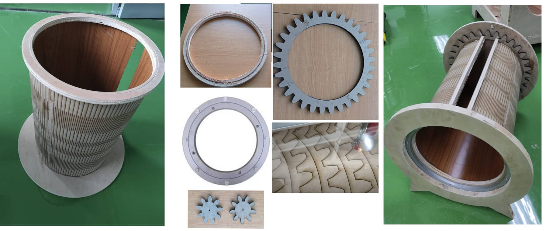
On the drum cylinder there are several important parts that are made:
- cylinder wall. This wall is made with mdf board and the process of making slots for kerf bending is carried out by laser cutting. The size made is sufficient to make a cylinder with a diameter of 40 cm and a length of 50 cm.
- front and back sides for wall mounting stands. The front side is made of plywood cut into cylinders and has a hole for the cat to enter. On the front side, the Kolahar ring turntable is added as a bearing and drum retainer from the front side. While on the back side added plywood and a hole for the sensor. To hold the rear cylinder added two rollers on the back side.
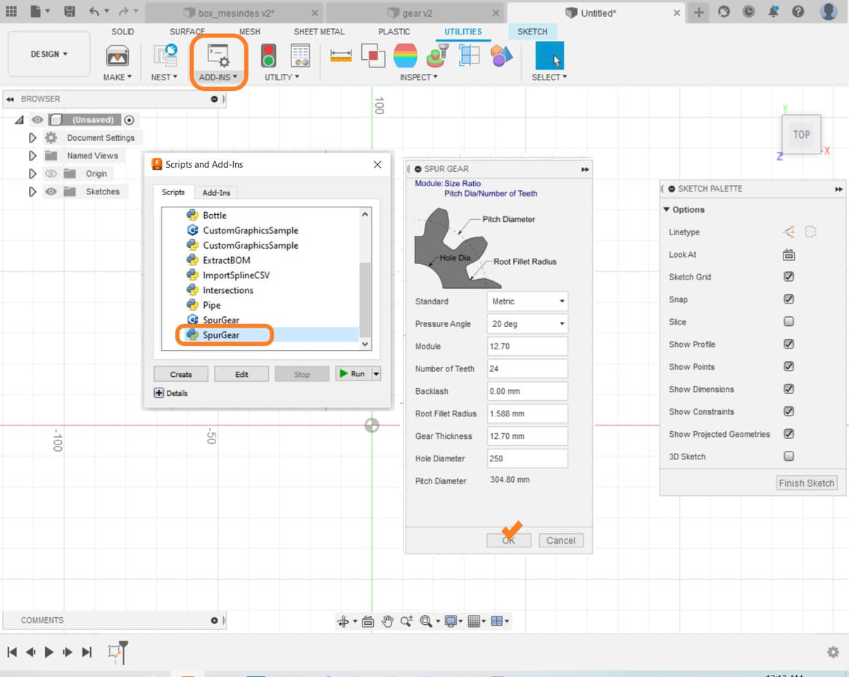
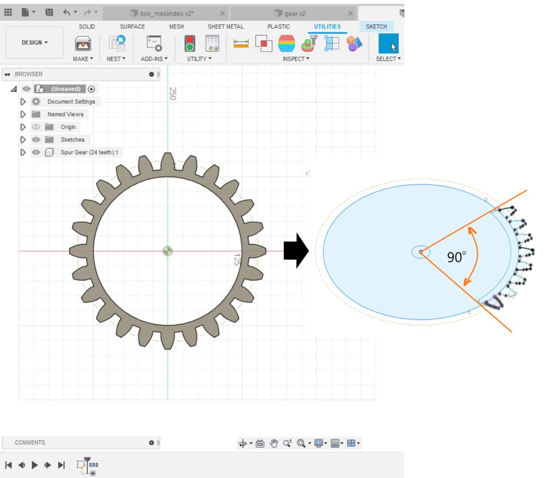
- gears. This gear is mounted on the rear side for power transmission to rotate the cylinder by the motor. Gear design using 360 fusion and manufactured with laser cutting. Because the size of the laser cutting machine is not sufficient for one operation, the design was modified by dividing the gear into 4 parts (each 90 degrees).
design and manufactur of gear
After all the parts for the drum cylinder are finished, the assembly process is carried out. The assembling process must be carried out carefully and accurate so that when making the cylinder, the position of the axis of rotation is completely symmetrical. So that when rotated the cylinder is not heavy and wobbly. After everything is fixed, the cylinder assembly can be strengthened with wood glue.
#Update for Alignment axis rotation for drum chamber
Setting the Axis
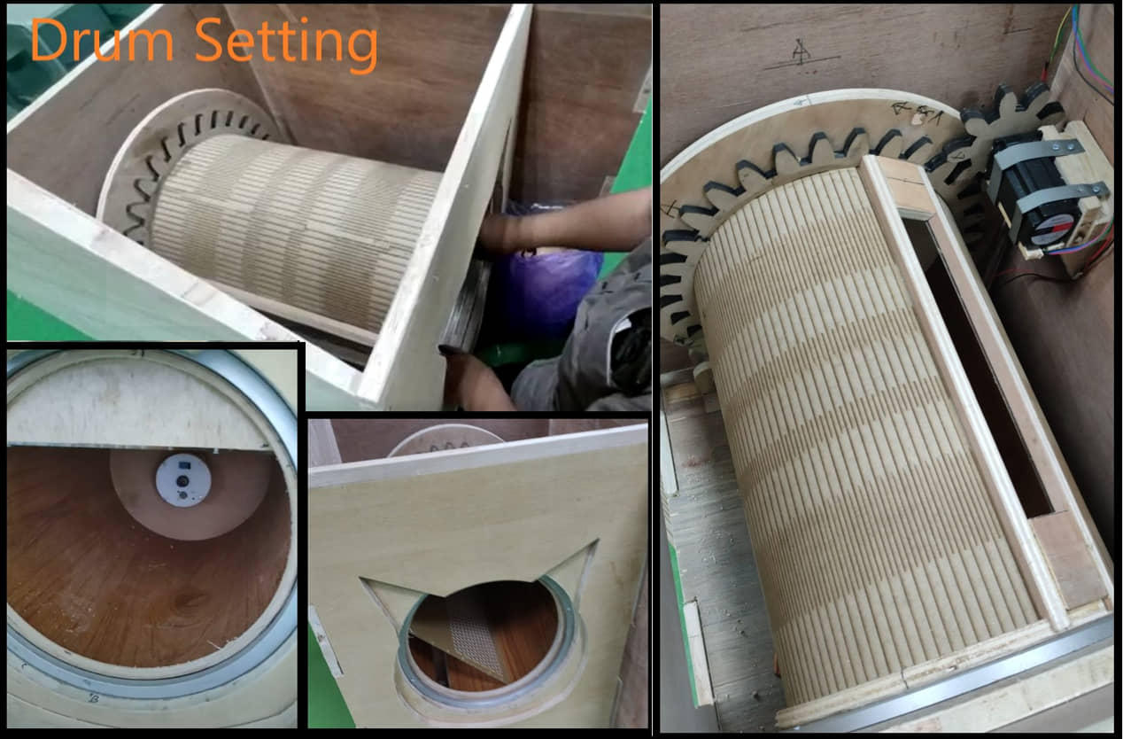
The important parts of the cylinder assembly are:
- alignment on the axis of rotation. When installing the cylinder on the wall of the box, it must be completely accurate against the front wall. while the rear is held by two roller bearings at the bottom. The cylinder is screwed securely and adjust the position of the rear retaining roller so that the cylinder rotates lightly.
- pinion gear position. After the cylinder can rotate manually properly, the gear motor is installed by adjusting the position so that it can move the gear pair properly. Check the motor rotation (speed and direction) with the motor test program while adjusting the motor position until the drum cylinder can rotate properly.
Setting the power transfer and rotation
Mechanical Production Galleries
Electronics
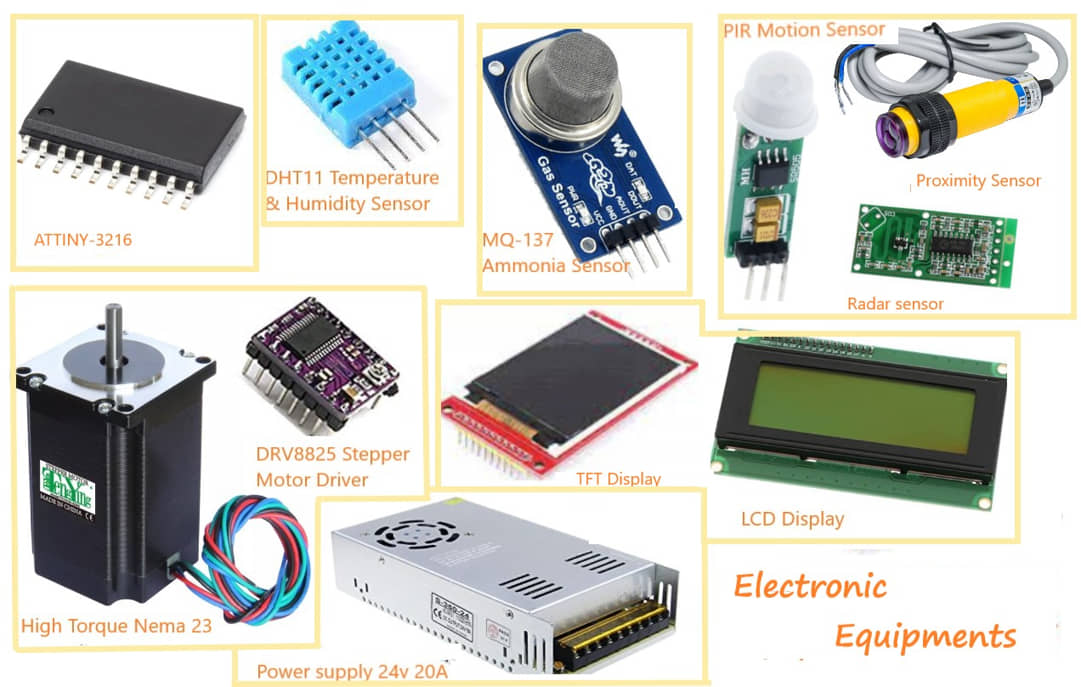
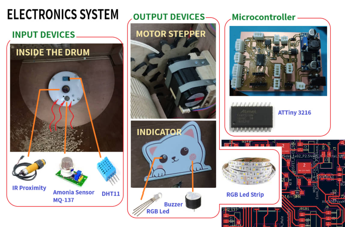
There are several electronic equipment that will be used (or alternative):
- Microcontroller: ATTiny 3216
- Temperature Sensor
- Humidity Sensor
- Ammonia Sensor
- LCD Panel / TFT 2.2”
- LED Display
- PIR Sensor/Radar sensor/Laser(distance sensor)
- Stepper Motor / DC (high torque)
- DC motor drivers
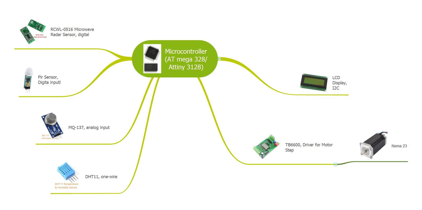
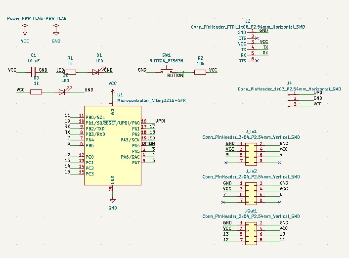
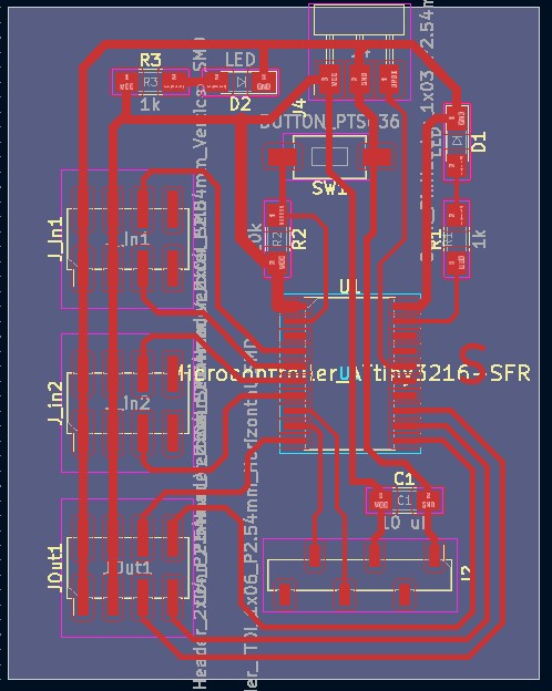
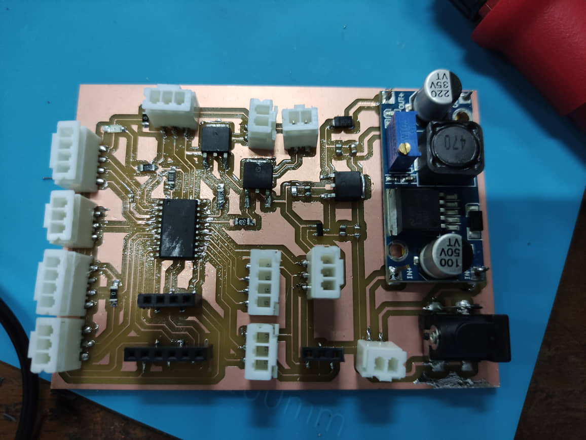
Next I made a circuit design for pcb
ATtiny 3216 Pin Assignment
to make sure which MCU I will use, I need to do a pin assignment to the system that I will use. Pin assignment is done by identifying the type of sensor (input) or actuator (output) that I use, the type of communication used with the MCU. The result is to determine the adequacy of the required pins. Because I use ATtiny 3128, the pin assignment results are as follows:
| No | Description | Pin Assignment | Pin |
|---|---|---|---|
| 1 | PIR/Radan Sensor/Laser | Digital Input | 6 |
| 1 | MQ-137 | Analog Input | 7 |
| 1 | DHT11 | One wire | 3 |
| 1 | LCD Display / TFT | I2C | 10, 11 |
| 1 | Modul Stepper TB6600 | Digital Output | 12, 13 |
#Update PCB for running all the system
I updated the schematic and PCB by adding a power supply and shield for connection with the required sensors and actuators.
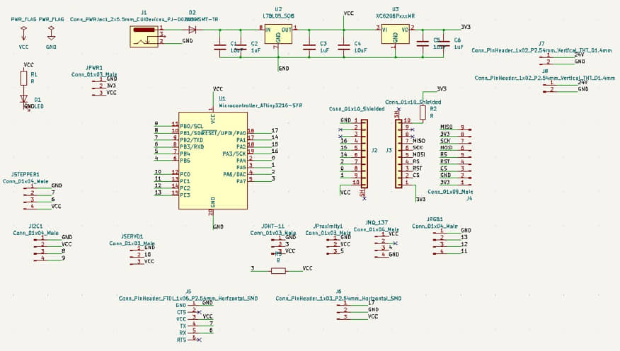
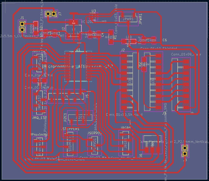
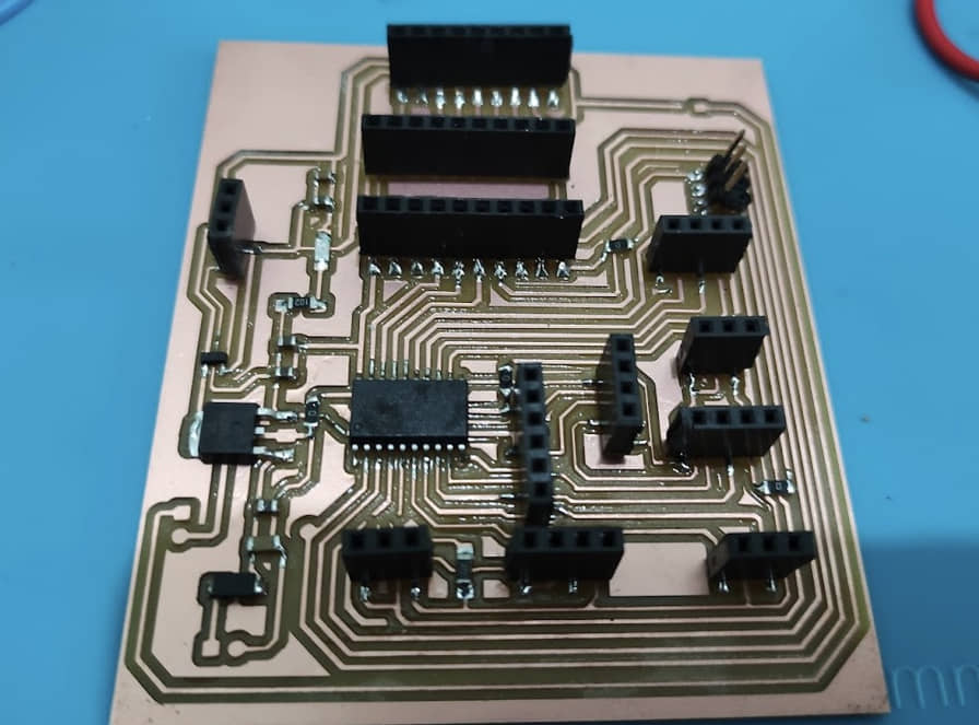
#Update PCB for machine
The test results with the previous PCB to read all sensors and run the output used are running well. But there is a slight update regarding the connector used. I’m trying to re-update the PCB using the JST connector so that the cable connection doesn’t come off easily.
Besides that, there are a few schematic changes. Based on some inputs from instructors from Asia review, the LCD/TFT which was previously used as an indicator is not needed and is changed to a simple indicator. I changed the display to an RGB LED that changes color according to the condition of the device. Therefore I need to revise the pin assignment and update the schematic/PCB again.
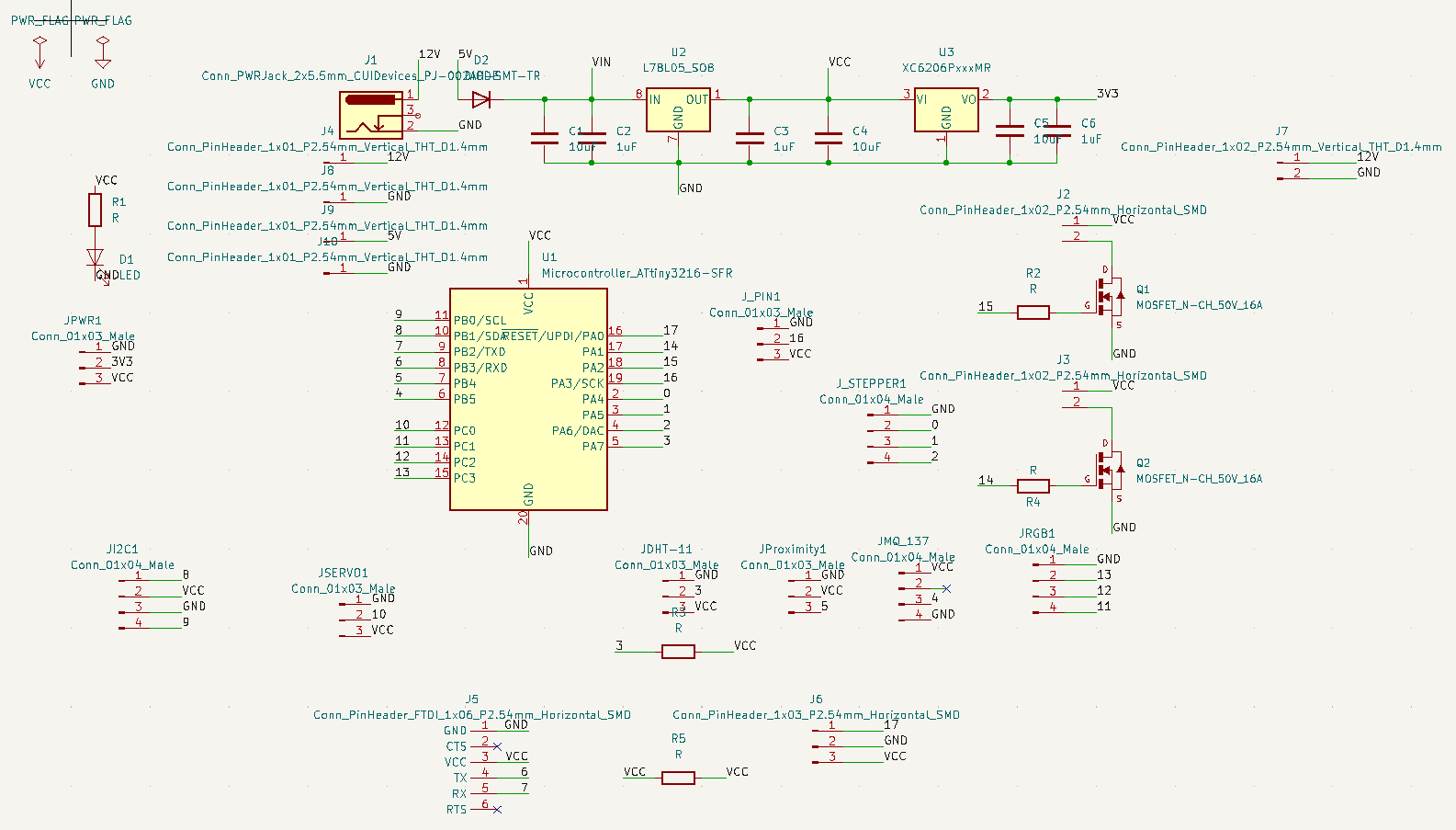
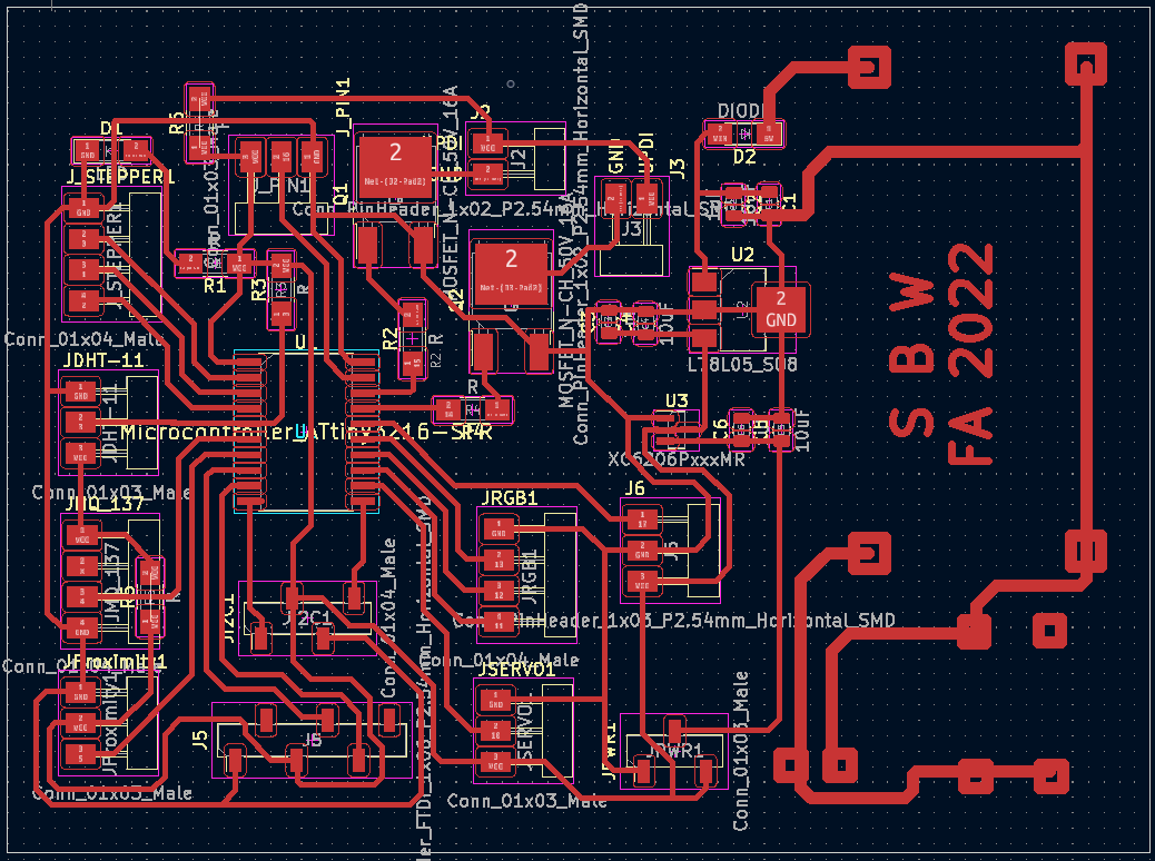
#Update for ATtiny 3216 Pin Assignment
| No | Description | Pin Assignment | Pin |
|---|---|---|---|
| 1 | IR Proximity sensor | Digital Input | 5 |
| 2 | MQ-137 | Analog Input | 4 |
| 3 | DHT11 | One wire | 3 |
| 4 | LED RGB | Digital Output | 11, 12, 13 |
| 5 | Modul Stepper TB6600 | Digital Output | 0, 1, 2 |
| 6 | Serial monitor | serial port | 6, 7 |
| 7 | Servo motor (if needed) | Digital Output | 10 |
| 8 | UPDI programming | UPDI port | 17 |
| 9 | I2C Port | I2C port | 8, 9 |
| 10 | Led Strip (Mosfet) | Digital Output | 14, 15 |
#Update for Input and output Devices
Programming
Some programming parts have been tested in weekly task sessions, such as reading the sensor section, or output devices. This project page documents programming that is specific to the case in the final project.
There are several stages in my coding program:
- make a program to read all sensors according to the working conditions of the machine,
- run the output device (motor, display) and adjust its configuration to suit the work of the machine,
- combine the two programs and check for problems that may arise according to the machine’s working algorithm.
- testing and evaluation
Initial testing for dummy condition
// First testing to integrated input and output devices as needed for final project
#include  <Wire.h>
#include  <LiquidCrystal_I2C.h>
#include <DFRobot_DHT11.h>
#include <MQ2.h>
DFRobot_DHT11 DHT;
LiquidCrystal_I2C lcd(0x27, 20,4);  // I2C adress
#define DHT11_PIN 3

const int IRPin=2;
const int ledPin = 16;
const int ledPinG = 10;
const int ledPinB = 12;
const int BuzPin = 1;
const int pin = 5;
int sensorValue = 0;
int prestate = 0;
int count=0;
int stat=0;
float lpg, co, smoke;
MQ2 mq2(pin);


void setup()
{
  Serial.begin(115200);
  pinMode(IRPin, INPUT);
  pinMode(ledPin, OUTPUT);
  pinMode(ledPinG, OUTPUT);
  pinMode(ledPinB, OUTPUT);
  pinMode(BuzPin, OUTPUT);

  mq2.begin();
  lcd.begin();
  lcd.backlight();
  delay(250);
  lcd.noBacklight();
  delay(250);
  lcd.backlight();
  lcd.setCursor(0,0);
  lcd.print("Fablab Kamakura");
  delay(1000);
  lcd.setCursor(0,1);
  lcd.print("Setyawan UGM");
  delay(2000);
  lcd.clear();
 // digitalWrite(BuzPin, HIGH);
}

void loop()
{
  DHT.read(DHT11_PIN);


  Serial.print("temperature:");
  Serial.print(DHT.temperature);
//  Serial.print(char(176));
  Serial.println("\u00b0 C");
  Serial.print("humidity :");
  Serial.print(DHT.humidity);
  Serial.println("%");
  lcd.setCursor(0,0);
  lcd.print("T:");
  lcd.setCursor(2,0);
  lcd.print(DHT.temperature);
  lcd.setCursor(5,0);
  lcd.print("H:");
  lcd.setCursor(7,0);
  lcd.print(DHT.humidity);

  float* values= mq2.read(true);
  lpg = mq2.readLPG();
  lcd.setCursor(10,0);
  lcd.print("LPG:");
  lcd.setCursor(14,0);
  lcd.print(lpg);
         lcd.setCursor(4,3);
        lcd.print("READY TO USE");

    sensorValue = digitalRead(IRPin);
    if(sensorValue==0){
          lcd.clear();
      if (count==stat){
             count++;
      }
       digitalWrite(ledPin, HIGH);
       digitalWrite(ledPinG, HIGH);
       digitalWrite(ledPinB, LOW);
       lcd.setCursor(0,2);
       lcd.print("IN USE");
       Serial.print("Status :");
       Serial.println("Full");
       Serial.println();
       prestate = 1;

    }
    else
    {
       digitalWrite(ledPin, LOW);
       digitalWrite(ledPinB, LOW);
       digitalWrite(ledPinG, LOW);
       lcd.setCursor(0,2);
       lcd.print("EMPTY ");
       Serial.print("Status :");
       Serial.println("Empty");
       Serial.println();
       stat = count;
       if (prestate == 1||lpg>2){
        for (int i=1; i<=10; i++) {
        digitalWrite(BuzPin, HIGH);
        digitalWrite(ledPinB, HIGH);
        delay(500);
        digitalWrite(BuzPin, LOW);
        digitalWrite(ledPinB, LOW);
        delay(700);
        lcd.setCursor(2,3);
        lcd.print("CHANGE THE LITTER");

        }
        lcd.clear();
       }
       prestate = 0;

}
 lcd.setCursor(12,2);
 lcd.print("Count");
 lcd.setCursor(18,2);
 lcd.print(count);

}
Update for testing the Input devices
#include  <Wire.h>
#include <DFRobot_DHT11.h>
#define DHT11_PIN 3
#define RL 47  //The value of resistor RL is 47K
#define m -0.263 //Enter calculated Slope
#define b 0.42 //Enter calculated intercept
#define Ro 24 //Enter found Ro value
#define MQ_sensor 4 //Sensor is connected to A4
DFRobot_DHT11 DHT;
const int irPin=5;
const int ledPinR = 16;
const int ledPinG = 15;
const int ledPinB = 14;
const int BuzPin = 2;
int prestate = 0;
int count=0;
int stat=0;

void setup() {
  Serial.begin(9600); //Initialise serial COM for displaying the value
  pinMode(irPin, INPUT);
  pinMode(ledPinR, OUTPUT);
  pinMode(ledPinG, OUTPUT);
  pinMode(ledPinB, OUTPUT);
  pinMode(BuzPin, OUTPUT);
}

void loop() {
  float VRL; //Voltage drop across the MQ sensor
  float Rs; //Sensor resistance at gas concentration
  float ratio; //Define variable for ratio
  DHT.read(DHT11_PIN);

  VRL = analogRead(MQ_sensor)*(5.0/1023.0); //Measure the voltage drop and convert to 0-5V
  Rs = ((5.0*RL)/VRL)-RL; //Use formula to get Rs value
  ratio = Rs/Ro;  // find ratio Rs/Ro
  float ppm = pow(10, ((log10(ratio)-b)/m)); //use formula to calculate ppm
  Serial.print("NH3(ppm) = "); //Display a ammonia in ppm
  Serial.print(ppm);
  Serial.print("   Temp(\u00b0C) = ");
  Serial.print(DHT.temperature);
  Serial.print("   Humi(%) = ");
  Serial.println(DHT.humidity);
//  Serial.print("Voltage = "); //Display a intro message
//  Serial.println(VRL);
  int irSensorValue = digitalRead(irPin);

    if(irSensorValue==0){
   //       lcd.clear();
      if (count==stat){
             count++;
      }
       digitalWrite(ledPinR, HIGH);
       digitalWrite(ledPinG, HIGH);
       digitalWrite(ledPinB, LOW);
//       lcd.setCursor(0,2);
//       lcd.print("IN USE");
       Serial.print("Status :");
       Serial.println("In Use");
       Serial.println();
       prestate = 1;

    }
    else
    {
       digitalWrite(ledPinR, LOW);
       digitalWrite(ledPinB, LOW);
       digitalWrite(ledPinG, HIGH);
//       lcd.setCursor(0,2);
//       lcd.print("EMPTY ");
       Serial.print("Status :");
       Serial.println("Empty");
       Serial.println();
       stat = count;
       if (prestate == 1||ppm>2){
        for (int i=1; i<=10; i++) {
        digitalWrite(BuzPin, HIGH);
        digitalWrite(ledPinB, HIGH);
        digitalWrite(ledPinG, LOW);
        delay(500);
        digitalWrite(BuzPin, LOW);
        digitalWrite(ledPinB, LOW);
        digitalWrite(ledPinG, LOW);
                Serial.println("Cleaning");
        delay(700);

//        lcd.setCursor(2,3);
//        lcd.print("CHANGE THE LITTER");

        }
 //       lcd.clear();
       }
       prestate = 0;
}
  delay(500);

}
testing for output devices
#include  <Wire.h>
#include <DFRobot_DHT11.h>
#include <AccelStepper.h>
#define DHT11_PIN 3
#define RL 47  //The value of resistor RL is 47K
#define m -0.263 //Enter calculated Slope
#define b 0.42 //Enter calculated intercept
#define Ro 24 //Enter found Ro value
#define MQ_sensor 4 //Sensor is connected to A4
#define dirPin 6
#define stepPin 7
#define enPin 0
#define stepsPerRevolution 160
#define stepsPerRevolution2 50

#define motorInterfaceType 1
AccelStepper stepper = AccelStepper(motorInterfaceType, stepPin, dirPin);
DFRobot_DHT11 DHT;
const int irPin=5;
const int ledPinR = 11;
const int ledPinG = 12;
const int ledPinB = 13;
const int BuzPin = 10;
int prestate = 0;
int count=0;
int stat=0;

void setup() {
  Serial.begin(9600); //Initialise serial COM for displaying the value
  pinMode(irPin, INPUT);
  pinMode(ledPinR, OUTPUT);
  pinMode(ledPinG, OUTPUT);
  pinMode(ledPinB, OUTPUT);
  pinMode(BuzPin, OUTPUT);
  pinMode(stepPin, OUTPUT);
  pinMode(dirPin, OUTPUT);
  pinMode(enPin, OUTPUT);
//  stepper.setMaxSpeed(1000);
//  stepper.setAcceleration(500);

 digitalWrite(enPin, HIGH);
}

void loop() {
  float VRL; //Voltage drop across the MQ sensor
  float Rs; //Sensor resistance at gas concentration
  float ratio; //Define variable for ratio
  DHT.read(DHT11_PIN);

  VRL = analogRead(MQ_sensor)*(5.0/1023.0); //Measure the voltage drop and convert to 0-5V
  Rs = ((5.0*RL)/VRL)-RL; //Use formula to get Rs value
  ratio = Rs/Ro;  // find ratio Rs/Ro
  float ppm = pow(10, ((log10(ratio)-b)/m)); //use formula to calculate ppm
  Serial.print("NH3(ppm) = "); //Display a ammonia in ppm
  Serial.print(ppm);
  Serial.print("   Temp(\u00b0C) = ");
  Serial.print(DHT.temperature);
  Serial.print("   Humi(%) = ");
  Serial.println(DHT.humidity);
//  Serial.print("Voltage = "); //Display a intro message
//  Serial.println(VRL);
  int irSensorValue = digitalRead(irPin);


    if(irSensorValue==0){
   //       lcd.clear();
      if (count==stat){
             count++;
      }
       digitalWrite(ledPinR, HIGH);
       digitalWrite(ledPinG, HIGH);
       digitalWrite(ledPinB, LOW);
//       lcd.setCursor(0,2);
//       lcd.print("IN USE");
       Serial.print("Status :");
       Serial.println("In Use");
       Serial.println();
       prestate = 1;

    }
    else
    {
       digitalWrite(ledPinR, LOW);
       digitalWrite(ledPinB, LOW);
       digitalWrite(ledPinG, HIGH);
//       lcd.setCursor(0,2);
//       lcd.print("EMPTY ");
       Serial.print("Status :");
       Serial.println("Empty");
        Serial.println("Ready for use");
               Serial.println();
       stat = count;
       if (prestate == 1||ppm>0.7){
       digitalWrite(ledPinB, HIGH);
       digitalWrite(ledPinG, LOW);
  // Set the spinning direction clockwise:
  digitalWrite(dirPin, HIGH);
  digitalWrite(enPin, LOW);
  // Spin the stepper motor 1 revolution slowly:
  for (int i = 0; i < stepsPerRevolution; i++) {
    // These four lines result in 1 step:
    Serial.println("Cleaning");
    digitalWrite(stepPin, HIGH);
    delayMicroseconds(1000);
    digitalWrite(stepPin, LOW);
    delayMicroseconds(1000);
  }
  delay(500);
  digitalWrite(dirPin, LOW);
    for (int i = 0; i < stepsPerRevolution2; i++) {
    // These four lines result in 1 step:
    Serial.println("Cleaning");
    digitalWrite(stepPin, HIGH);
    delayMicroseconds(2000);
    digitalWrite(stepPin, LOW);
    delayMicroseconds(2000);
    }
    delay(500);
  digitalWrite(dirPin, HIGH);
  // Spin the stepper motor 1 revolution slowly:
  for (int i = 0; i < stepsPerRevolution; i++) {
    // These four lines result in 1 step:
    Serial.println("Cleaning");
    digitalWrite(stepPin, HIGH);
    delayMicroseconds(1000);
    digitalWrite(stepPin, LOW);
    delayMicroseconds(1000);
  }
        for (int k=1; k<=5; k++) {
        digitalWrite(enPin, HIGH);
        digitalWrite(BuzPin, HIGH);
        digitalWrite(ledPinB, HIGH);
        digitalWrite(ledPinG, LOW);
        delay(500);
        digitalWrite(BuzPin, LOW);
        digitalWrite(ledPinB, LOW);
        digitalWrite(ledPinG, LOW);
        Serial.println("Cleaning");
        delay(700);
        }
//        lcd.setCursor(2,3);
//        lcd.print("CHANGE THE LITTER");

 //       }
 //       lcd.clear();
       }
       prestate = 0;
       digitalWrite(enPin, HIGH);
 //Serial.println(prestate);
}


  delay(300);

}
Update for Running Stepper Motor
/* Example sketch to control a stepper motor with TB6600 stepper motor driver, AccelStepper library and Arduino: acceleration and deceleration. More info: https://www.makerguides.com */

// Include the AccelStepper library:
#include <AccelStepper.h>

// Define stepper motor connections and motor interface type. Motor interface type must be set to 1 when using a driver:
#define dirPin 6
#define stepPin 7
#define enPin 0
#define motorInterfaceType 1

// Create a new instance of the AccelStepper class:
AccelStepper stepper = AccelStepper(motorInterfaceType, stepPin, dirPin);

void setup() {
  // Set the maximum speed and acceleration:
  stepper.setMaxSpeed(500);
  stepper.setAcceleration(100);
  pinMode(enPin, OUTPUT);
     digitalWrite(enPin, HIGH);
}

void loop() {
  digitalWrite(enPin, LOW);
  // Set the target position:
  stepper.moveTo(3600);
  // Run to target position with set speed and acceleration/deceleration:
  stepper.runToPosition();

  delay(1000);

  // Move back to zero:
  stepper.moveTo(0);
  stepper.runToPosition();

  delay(1000);
}
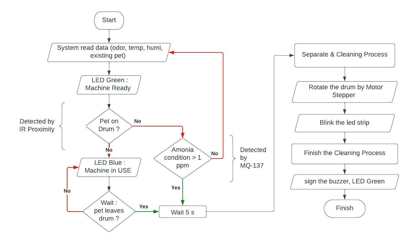
#Update for algorithm
From the results of the discussion on how the machine works, then I determine the machine’s working algorithm as follows:
Update the Integrated System (Final)
/* the source code are taken from various sources */
#include  <Wire.h>
#include <DFRobot_DHT11.h>
#include <AccelStepper.h>
#define DHT11_PIN 3
#define RL 47  //The value of resistor RL is 47K
#define m -0.263 //Enter calculated Slope
#define b 0.42 //Enter calculated intercept
#define Ro 24 //Enter found Ro value
#define MQ_sensor 4 //Sensor is connected to A4

// Include the AccelStepper library:
#include <AccelStepper.h>

// Define stepper motor connections and motor interface type. Motor interface type must be set to 1 when using a driver:
#define dirPin 6
#define stepPin 7
#define enPin 0
#define motorInterfaceType 1
#define irPin 5
#define ledPinR 11
#define ledPinG 13
#define ledPinB 12
#define BuzPin 10

int count=0;
// Create a new instance of the AccelStepper class:
AccelStepper stepper = AccelStepper(motorInterfaceType, stepPin, dirPin);
DFRobot_DHT11 DHT;
void setup() {
  Serial.begin(9600); //Initialise serial COM for displaying the value
  // Set the maximum speed and acceleration:
  stepper.setMaxSpeed(500);
  stepper.setAcceleration(100);
  pinMode(enPin, OUTPUT);
  pinMode(irPin, INPUT);
  pinMode(ledPinR, OUTPUT);
  pinMode(ledPinG, OUTPUT);
  pinMode(ledPinB, OUTPUT);
  pinMode(BuzPin, OUTPUT);
  digitalWrite(ledPinR, LOW); //led strip off
  digitalWrite(ledPinG, LOW);  //led Green on
  digitalWrite(ledPinB, HIGH); //led Blue off
  digitalWrite(BuzPin, HIGH); //buzzer off
  digitalWrite(enPin, HIGH);
}

void loop() {
    float VRL; //Voltage drop across the MQ sensor
  float Rs; //Sensor resistance at gas concentration
  float ratio; //Define variable for ratio
  DHT.read(DHT11_PIN);

  VRL = analogRead(MQ_sensor)*(5.0/1023.0); //Measure the voltage drop and convert to 0-5V
  Rs = ((5.0*RL)/VRL)-RL; //Use formula to get Rs value
  ratio = Rs/Ro;  // find ratio Rs/Ro
  float ppm = pow(10, ((log10(ratio)-b)/m)); //use formula to calculate ppm
  Serial.print("NH3(ppm) = "); //Display a ammonia in ppm
  Serial.print(ppm);
  Serial.print("   Temp(\u00b0C) = ");
  Serial.print(DHT.temperature);
  Serial.print("   Humi(%) = ");
  Serial.println(DHT.humidity);
  Serial.println("Empty-Ready for use");
   int irSensorValue = digitalRead(irPin);
       if(irSensorValue==1){
       digitalWrite(ledPinR, LOW); //led strip off
       digitalWrite(ledPinG, HIGH);  //led Green of
       digitalWrite(ledPinB, LOW); //led Blue on
       digitalWrite(BuzPin, HIGH); //buzzer off
        Serial.println("In USE");
          count = 1;
          delay (5000);
       }
        else {


          if (count==1){

  digitalWrite(enPin, LOW);
        digitalWrite(ledPinG, HIGH);  //led Green of
       digitalWrite(ledPinB, LOW); //led Blue on
       digitalWrite(ledPinR, HIGH); //led strip on
       Serial.println("Cleaning");
  // Set the target position:
  stepper.moveTo(3600);
  // Run to target position with set speed and acceleration/deceleration:
  stepper.runToPosition();

  delay(1000);


  // Move back to zero:
  stepper.moveTo(0);
  stepper.runToPosition();

  delay(1000);
  count=0;

        digitalWrite(ledPinR, HIGH);
       digitalWrite(ledPinB, HIGH);


        digitalWrite(BuzPin, LOW);
        digitalWrite(ledPinB, LOW);
        delay(500);
        digitalWrite(BuzPin, HIGH);
        digitalWrite(ledPinB, HIGH);
        Serial.println("Cleaning");
        delay(700);
        digitalWrite(BuzPin, LOW);
        digitalWrite(ledPinB, LOW);
        delay(500);
        digitalWrite(BuzPin, HIGH);
        digitalWrite(ledPinB, HIGH);
        Serial.println("Cleaning");
        delay(700);        digitalWrite(BuzPin, LOW);
        digitalWrite(ledPinB, LOW);
        delay(500);
        digitalWrite(BuzPin, HIGH);
        digitalWrite(ledPinB, HIGH);
        Serial.println("Cleaning");
        delay(700);
        digitalWrite(ledPinB, LOW);
        delay(500);
        digitalWrite(BuzPin, HIGH);
        digitalWrite(ledPinB, HIGH);
        Serial.println("Finish");
        delay(1000);

}
}
digitalWrite(enPin, HIGH);
       digitalWrite(ledPinR, LOW); //led strip off
       digitalWrite(ledPinG, LOW);  //led Green on
       digitalWrite(ledPinB, HIGH); //led Blue off
       digitalWrite(BuzPin, HIGH); //buzzer off
delay (300);
}
Electonics Production Galleries
Materials
The material requirements for this final project can be seen in the following table:
Note
as a note after several evaluations there are some parts that need to be updated, so that some are strike-through and some are added to this list.
| Qty | Description | Price | Link | Notes |
|---|---|---|---|---|
| 4 | Plywood 18mm | 18.20 $ | Local market | |
| 1 | MCU: Attiny 3216 | 9.60 $ | Digikey | |
| 1 | Ammonia sensor MQ-137 | 22.00 $ | Amazon | |
| 1 | High torque Nema 23 stepper | 39.99 $ | Amazon | |
| 1 | Temperatur & Humidity sensor DHT-11 | 9.99 $ | Amazon | |
| 1 | LED | 6.99 $ | Amazon | |
| 1 | RGB Led | 7.98 $ | Amazon | |
| 1 | Power supply 24v 20A | 44.99 $ | Amazon | |
| 1 | PCB Board FR-1 | 2.00 $ | ||
| 1 | Bearing | 4.00 $ | Amazon | |
| 1 | TB6600 Stepper Motor Driver | 15.99 $ | Amazon | |
| 1 | IR Proximity Switch | 12.99 $ | Amazon | |
| 1 | Buzzer Active | 6.98 $ | Amazon | |
| 1 | Acrylic 12 in x 24 in | 35.95 $ | Amazon | |
| 1 | JST-XH Connector Kit | 11.99 $ | Amazon | |
| 2 | Dupont Jumper Wires | 9.79 $ | Amazon |
The total material price is around USD 341.84 (not including the cost of processing and simple consumables such as lead, flux, screws, etc.)
Lisense
For this project I granted the license under Attribution-ShareAlike 4.0 International (CC BY-SA 4.0)


Acknowledgment
Special thanks to :
- Prof. Neil Gershenfeld
- Fablab Kamakura (Youka Watanabe)
- Instructors : Phanuwit “Rico” Kanthatham, Jun Kawahara, Toshiki Tsuchiyama, Yosuke Tsuchiya, Masato Takemura
- Assistant Instructor : Georg Tremmel
- Students 2022 : Kurniawan Prasetya, Jans Hendry, Atsufumi Suzuki, Kurumi Shiowaki
- TCP JICA-UGM Team
- my UGM colleague : Riki Purnama, Muji Raharjo
Documentation Files
- 2D Design Logo (.svg)
- 2D Design Sticker Pet Lover (.svg)
- Vector Design of wall box for Milling (.dxf)
- Toolpath of wall for Milling part1 (.tap)
- Toolpath of wall for Milling part2(.tap)
- Toolpath of wall for Milling part3(.tap)
- Vector Design of roof for Milling (.dxf)
- Toolpath of roof for Milling (.tap)
- Kerf-Bending Vector Design of cylinder drum (.dxf)
- PCB board for FP trace (.svg)
- PCB board for FP interior (.svg)
- KiCAD PCB board for FP (.zip)
- Coding program for FP (.ino)