14. Interface and application programming
Week 14 : To do checklist
- Learn about Interface and application programming
- Individual Practice
- make connection MCU with analog input and RGB led as output
- Programming using processing as output interface
- Programming using processing for Input interface
- Group work
- Make program for interface with other program
- Repo to push group work (Kamakura) 2022
- Continue the final Project Process
- Documentations
Assignment (week 14):
Individual assignment:
- write an application that interfaces a user with an input &/or output device that you made
Group assignment:
- compare as many tool options as possible
Learning Outcomes
- Interpret and implement design and programming protocols to create a Graphic User Interface (GUI)
This week I worked on Networking and communications
Please click the button for Group Assignment
In this task, I try to use processing for interfaces as both output and input.
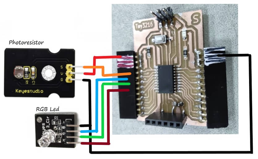
I made a simple circuit using the ATtiny 3216 MCU which I made the week before. This circuit connects the photoresistor (as an input device), RGB Led (as an output device) with the MCU. Next, an interface will be created that will visualize the reading of data from the sensor, and an interface for the command to turn on the LED.
Interface as Output
In this program I will capture light sensor data (photoresistor) using the ATtiny 3216 MCU. From the data obtained, it will be sent via a serial monitor. The processing section will capture serial monitor data received by the computer (COM port). The data is processed by processing in the form of visualization (bar). The more light the sensor receives, the higher the bar will rise and the color will turn red.
Program at MCU (Attiny 3216), the sketch below will be uploaded, this program is to read the photoresistor sensor on pin.2 and the data is sent to the serial monitor.
int sensorPin =2 ;
int value = 0;
void setup()
{
 Serial.begin(9600); }
void loop()
{
 value = analogRead(sensorPin);

Serial.println(value, DEC);

delay(50);
}
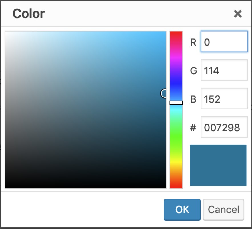
To make the interface attractive, I need to make the object colorful. I can use the color data (RGB) from color picker in the image software (paint, inkscape, etc.)
On the processing run the following program:
import processing.serial.*;

Serial mySerial;

String myString = null;
int nl = 10;
float r=0, g=100;

float myVal;

void setup(){
  size(200,600);

  mySerial = new Serial(this, "COM28", 9600); //type your port name in the middle
}

void draw(){

 while (mySerial. available() > 0) {
   myString = mySerial.readStringUntil(nl);

   if (myString != null){
   background(150,10,100); //change the color
   myVal = float(myString);

   myVal = myVal/1000* height;

  rectMode(CENTER);
  r = myVal/2;
  g=255-r;
  fill(r, g, 00);
  rect(width/2, height-(myVal/2), 100, myVal);

  stroke(100,100,100);
  fill(200, 60, 0);
  textSize(30);
  text(r, width/2-50, height/2);
}
 }
  }
Result :
Interface as Input
I use Processing to visualize the input data reading interface. In this program I created a three-button interface to turn on the ATtiny 3216 RGB lights.
On the MCU I uploaded a sketch to detect data from the serial monitor, the data received will be used to select the RGB lighting
char val;
int ledPinR = 3;
int ledPinG = 4;
int ledPinB = 5;

void setup(){
  Serial.begin(9600); //initiate serial communication at 9600 baud/sec
  pinMode(3, OUTPUT); //sets pin 3 as output
  pinMode(4, OUTPUT); //sets pin 4 as output
  pinMode(5, OUTPUT); //sets pin 5 as output
}

void loop(){
  if (Serial.available()) {

    val = Serial.read(); //create 'character' datatype variable 'val'

    if (val == 'r'){ //if 'g' received over serial
      digitalWrite(ledPinR,HIGH); //turn LED ON
    }
    else if (val == 'g'){ //if 'g' received over serial
      digitalWrite(ledPinG,HIGH); //turn LED ON
    }
    else if (val == 'b'){ //if 'g' received over serial
      digitalWrite(ledPinB,HIGH); //turn LED ON
    }
    else {
      digitalWrite(ledPinR,LOW); //turn LED OFF
      digitalWrite(ledPinG,LOW); //turn LED OFF
      digitalWrite(ledPinB,LOW); //turn LED OFF
  }
  delay(10);
}
}
Processing is run will show up three buttons (Red, Green, Blue), when the mouse is clicked on the Red button it will change the color to bright and send R data, as well as if the mouse is clicked on the Green or Blue button.
import processing.serial.*;
Serial port;


void setup(){
  size(500,300); //pixels
  noCursor();
//  String portName = Serial.list()[0];
  port = new Serial(this, "COM28", 9600); //set 'port' varialble equal to new Serial object connected to same COM port as in Arduino at 9600 baud/s
}

void draw(){
  background(100); //greyscale...0 is black, 255 is white

  //Button
  //Conditional statement...button color depends on Pointer position
  if (mouseX > 50 && mouseX < 150 && mouseY > 150 && mouseY < 350 && mousePressed) {
    fill(250, 0, 0);
    circle(width/2-150, height/2, 100);
    fill(0, 100, 0);
    circle(width/2, height/2, 100);
    fill(0, 0, 100);
    circle(width/2+150, height/2, 100);
    port.write('r');
  }
  else if (mouseX > 200 && mouseX < 300 && mouseY > 150 && mouseY < 350 && mousePressed) {
    fill(0, 250, 0);
    circle(width/2, height/2, 100);
    fill(100, 0, 0);
    circle(width/2-150, height/2, 100);
    fill(0, 0, 100);
    circle(width/2+150, height/2, 100);
    port.write('g');
  }
    else if (mouseX > 350 && mouseX < 450 && mouseY > 150 && mouseY < 350 && mousePressed) {
    fill(0, 0, 250);
    circle(width/2+150, height/2, 100);
    fill(100, 0, 0);
    circle(width/2-150, height/2, 100);
    fill(0, 100, 0);
    circle(width/2, height/2, 100);
    port.write('b');
  }
  else {
  fill(100, 0, 0);
  circle(width/2-150, height/2, 100);
  fill(0, 100, 0);
  circle(width/2, height/2, 100);
  fill(0, 0, 100);
  circle(width/2+150, height/2, 100);
    port.write('0');
  }
  stroke(0,0,100);
  strokeWeight(5);


  //Pointer
  fill(200,100,0);
  noStroke();
  circle(mouseX, mouseY, 30);
}
Result :
Comparison with some other interfaces
For our group assignment, we compared the use of three different tools(different programming), namely:
- Processing
- Tkinter (Python)
- C# (Visual Studio)
The full results can be seen in the Group assignment
comment :
Utilization of the interface is very interesting, to visually describe in detail the results of the process (output) by the MCU or represent data input (input). Communication is required between the microcontroller and the computer, usually using a serial port. The data can be sent via the serial port and then processed by the computer, this system makes the MCU work lighter than the data processed in the MCU.
To ensure the interfacing system can work, we specify:
- graphs that will show data visualization in the form of variables that can change according to incoming data (processed data)
- The communication between the MCU and the computer is well confirmed, including the types of data sent and received
- the graphical interface function as input then the data will be sent from the computer to the MCU, otherwise if the function is as a display (output) then the data will be sent from the MCU to the computer
- Graphical interface can be set with a variety of more attractive colors
References
- Kamakura : Week 14 - Interface and Application Programming
- Processing + Microcontroller via Serial - Kamakura local session
- Processing tutorials
- 2D Animation & Interaction
- Graphical User Interfaces with Tk
Documentation Files
Group assignment learning
- In the group assignment, we try several type of interfacing programming
- Understanding the variation of interface to show the data visualization or command from/to MCU
Lessons learned (week 14 : Interface and Application Programming):
- Understanding of programming language for interfacing
- Understanding to make the visualization of data from serial
- Understand how to program interface for data communication as Input or Output