12. Input Device
Week 12 : To do checklist
- Learn about pin assignment of MCU as input (ATtiny 3128)
- Individual Practice
- Read the datasheet of each input device (analog/digital sensor)
- Programming MCU to capture data from the input device (ATtiny 3128)
- display the results to the output device
- Group work
- probe an input device’s analog levels and digital signals
- Repo to push group work (Kamakura) 2022
- Continue the final Project Process
- Documentations
Assignment (week 12):
Individual assignment:
- measure something: add a sensor to a microcontroller board that you have designed and read it
Group assignment:
- probe an input device’s analog levels and digital signals
This week I worked on Input devices
Please click the button for Group Assignment
A Sensor is part of the input devices. Sensor is a device that produces an output signal for the purpose of sensing of a physical phenomenon.
In the broadest definition, a sensor is a device, module, machine, or subsystem that detects events or changes in its environment and sends the information to other electronics, frequently a computer processor. Sensors are always used with other electronics (wikipedia).
There are various kinds of sensors that can be used to detect environmental conditions. both analog and digital. The use of sensors must first see the sensor specifications which can be seen in the sensor datasheet.
This week I tried to make a program for several input devices, including:
- Temperature and Humidity Sensor (DHT11) - One wire
- Photoresistor sensor (analog)
- Ultrasonic distance sensor
- Proximity Sensor (digital)
- Gas Sensor (analog)
The MCU I use is ATTINY 3216 which I previously designed in week 6
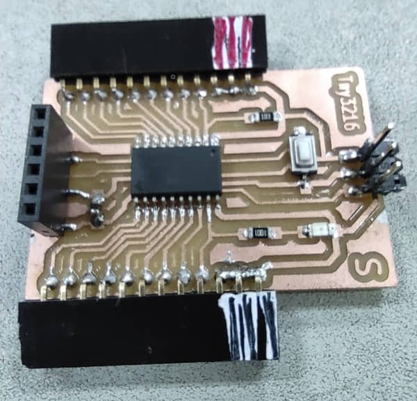
Create board for sensors connector
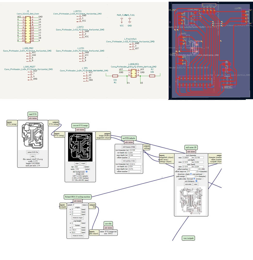
as the instructions on the 12th week assignment (input device), the sensor device will be connected to the MCU using the board, so I have to first design the board that will be used to connect the sensor to the MCU. On this board I designed connections from the MCU to several sensors that I will most likely use in the final project. The schematic and board designs are as follows:
To display the sensor readings I also use an output device in the form of an LCD Display 20x4 I2C. It is also displayed on the serial monitor.
here’s the PCB I used to assemble some sensors. but in this task I will try them one by one and then try to combine the sensors needed for the final project.
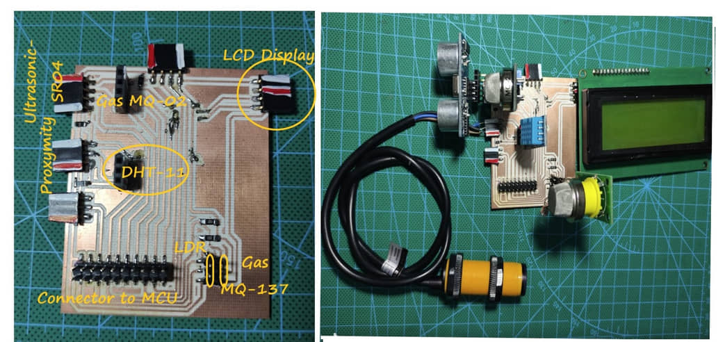
The overall connection with the MCU that I use in this task is as shown below:
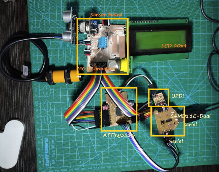
For programmers I use SAMD11C which is made dual serial (continuous from week 2) so that I can upload sketches as well as monitor communication to the MCU (attiny 3216). All GPIO ports from Attiny are connected to the sensor board and one of them (SDA and SCL) is used for LCD displays.
Sensor for Temperature and Humidity
To capture these two physical properties I use the DHT-11 sensor. The datasheet of this sensor can be found at here.
The DHT11 is a basic, ultra low-cost digital temperature and humidity sensor. It uses a capacitive humidity sensor and a thermistor to measure the surrounding air, and spits out a digital signal on the data pin (no analog input pins needed). Its fairly simple to use, but requires careful timing to grab data.
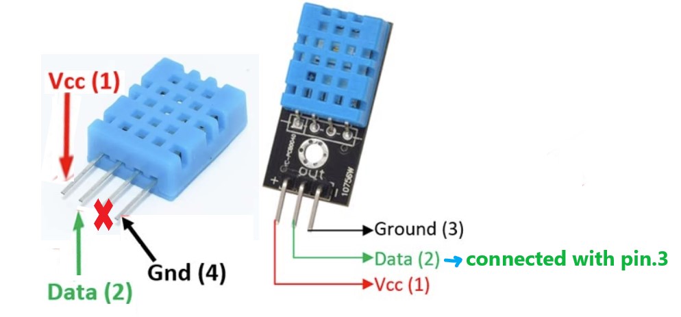
In this task I tried to use DHT-11 to sense temperature and humidity by connecting to the sensor board that I made with the connection on pin3 on my MCU.
The program below is a program to read the DHT-11 sensor and display the temperature and humidity values on the I2C LCD display and serial monitor. This program requires the DHT-11 library which can be downloaded at: DHT-11 library
#include  <Wire.h>
#include  <LiquidCrystal_I2C.h>
#include <DFRobot_DHT11.h>
DFRobot_DHT11 DHT;
#define DHT11_PIN 3


LiquidCrystal_I2C lcd(0x27, 20,4);  // Change 0x27 with your I2C address

void setup()
{

  Serial.begin(115200);

  lcd.begin();
  lcd.backlight();
  delay(250);
  lcd.noBacklight();
  delay(250);
  lcd.backlight();

  lcd.setCursor(0,0);
  lcd.print("Fablab Kamakura");
  delay(1000);
  lcd.setCursor(0,1);
  lcd.print("Setyawan UGM");
  delay(2000);
      lcd.clear();
}

void loop()
{

  DHT.read(DHT11_PIN);
  Serial.print("temperature:");
  Serial.print(DHT.temperature);
  Serial.print("humidity :");
  Serial.println(DHT.humidity);
  lcd.setCursor(0,0);
  lcd.print("Temperature:");
  lcd.setCursor(13,0);
  lcd.print(DHT.temperature);
  lcd.setCursor(0,1);
  lcd.print("Humidity   :");
  lcd.setCursor(13,1);
  lcd.print(DHT.humidity);
  delay(200);

}

Photoresistor Sensor
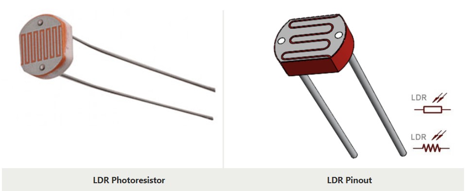
A Photoresistor or LDR (Light Dependent Resistor) is a resistor which made of semi-conductor material,and the conductance changes with luminance variation .The photoresistor can be manufactured with different figures and illuminated area based on this characteristic. As the name suggests will change it resistance based on the light around it. This property helps the LDR to be used as a Light Sensor. It can detect the amount of light falling on it and thus can predict days and nights.
we can find the shape of the photoresistor as follows (source: components101.com). We can get a sample LDR datasheet here
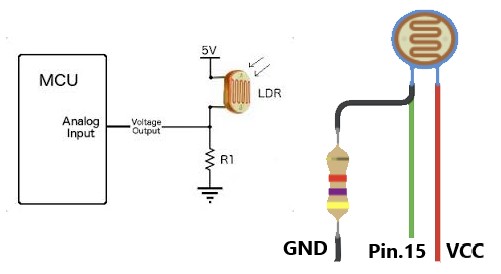
In this program I will use the LDR as a light sensor. The ambient light received by the LDR will be captured as an analog signal and processed by the MCU via the analog input (pin.15). The received data is processed and used to decide the conditions of day or night. The results of this decision are used to state the night or day conditions written on the LCD and serial monitor and also turn on the MCU’s internal light (pin.16) during night conditions.
#include  <LiquidCrystal_I2C.h>
LiquidCrystal_I2C lcd(0x27, 20,4);
int ldr = 15; // analog pin 3
int ledPin = 16; // led
int val ;

void setup()
{
  pinMode(ldr,INPUT);
  pinMode(ledPin, OUTPUT);
  Serial.begin(9600);
  lcd.begin();
  lcd.backlight();
  delay(50);
  lcd.noBacklight();
  delay(50);
  lcd.backlight();
  lcd.setCursor(0,0);
  lcd.print("Fablab Kamakura");
  delay(500);
  lcd.setCursor(0,1);
  lcd.print("Setyawan UGM");
  delay(500);
  lcd.clear();
}

void loop()
{
  val=analogRead(ldr);
  Serial.print("LDR value :");
  Serial.print(val);
  if (val<300){  //decision for Night and Day
     Serial.println("--> Night");
     digitalWrite(ledPin, HIGH);
     lcd.setCursor(0,2);
     lcd.print("LDR value :");
     lcd.setCursor(13,2);
     lcd.print(val);
     lcd.setCursor(0,3);
     lcd.print("Status :");
     lcd.setCursor(13,3);
     lcd.print("Night");
     lcd.clear();
  }
  else {
     Serial.println("--> Day");
     digitalWrite(ledPin, LOW);
     lcd.setCursor(0,2);
     lcd.print("LDR value :");
     lcd.setCursor(13,2);
     lcd.print(val);
     lcd.setCursor(0,3);
     lcd.print("Status :");
     lcd.setCursor(13,3);
     lcd.print("Day");
     lcd.clear();
  }

}
Visualization data with Python
For visualization purposes, we can also use interfacing with computers using python programming. In this task I try to visualize the photoresistor data. The data obtained from the sensor is sent via serial data (COMxx). serial data is captured by Python and displayed in the form of a graph (a circle variable that changes its diameter).
import tkinter
from tkinter import *
from time import *
import serial

arduinoData = serial.Serial('COM25', 9600)
master = Tk()

canvas = Canvas(master, width = 700, height = 700)
canvas.pack()

center_x = 350
center_y = 350
circle_size = 10

canvas.create_oval( center_x-circle_size, center_y-circle_size, center_x+circle_size, center_y+circle_size,fill = "red", tags = "circle1")
teksLabel = Label(master, text="Light Sensor", width=20, height=5)
teksLabel.pack()

def resize_circle_blue():
    global circle_size
    global canvas
    while True:
        myData = arduinoData.readline().strip()
        circle_size = int(myData)/2

        canvas.delete('circle1')
        canvas.create_oval( center_x-circle_size, center_y-circle_size, center_x+circle_size, center_y+circle_size,fill = "red", tags = "circle1")
        canvas.update()
        sleep(0.001)

master.after(100, resize_circle_blue)
master.mainloop()
Ultrasonic distance sensor
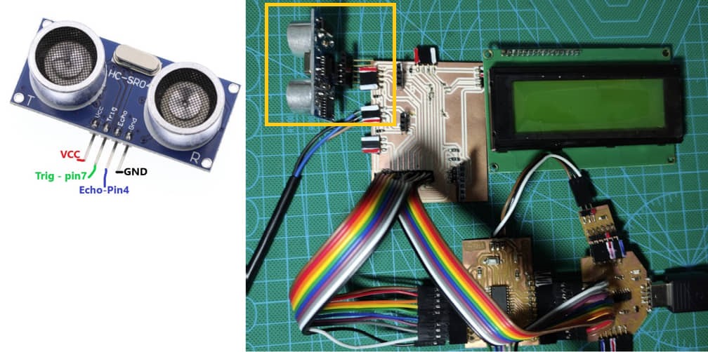
An ultrasonic sensor is an instrument that measures the distance to an object using ultrasonic sound waves. An ultrasonic sensor uses a transducer to send and receive ultrasonic pulses that relay back information about an object’s proximity. the datasheet can be viewed here
How the HC-SR04 Ultrasonic Distance Sensor Works? It emits an ultrasound at 40 000 Hz which travels through the air and if there is an object or obstacle on its path It will bounce back to the module. Considering the travel time and the speed of the sound you can calculate the distance (source : howtomechatronics.com).
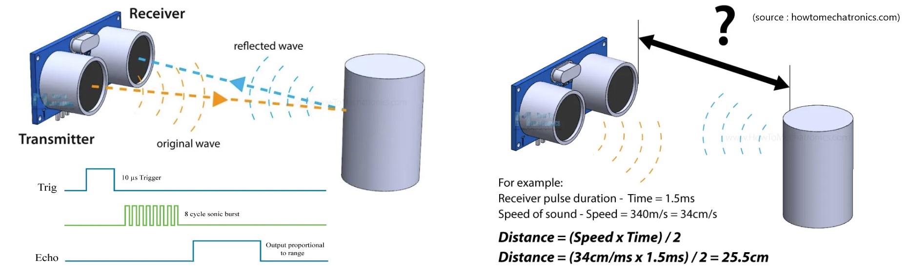
in this program we try to access the SR04 sensor and try to provide a barrier to get the measuring distance in several distance variations. The measurement results are displayed on the LCD display and serial monitor. We connect Echo-pin to pin 4 while trigger we connect to pin 7 on MCU.
#define echoPin 4 //Echo Pin
#define trigPin 7 //Trigger Pin
#include  <LiquidCrystal_I2C.h>
LiquidCrystal_I2C lcd(0x27, 20,4);

float duration, distance;

void setup() {
Serial.begin (9600);
//pin declarations
  pinMode(trigPin, OUTPUT);
  pinMode(echoPin, INPUT);
  lcd.begin();
  lcd.backlight();
  delay(50);
  lcd.noBacklight();
  delay(50);
  lcd.backlight();
  lcd.setCursor(0,0);
  lcd.print("Fablab Kamakura");
  delay(500);
  lcd.setCursor(0,1);
  lcd.print("Setyawan UGM");
  delay(500);
  lcd.clear();
  lcd.setCursor(0,0);
  lcd.print("Sensor HC-SR04 Test");
}

void loop() {
  digitalWrite(trigPin, LOW);delayMicroseconds(2);
  digitalWrite(trigPin, HIGH);delayMicroseconds(10);
  digitalWrite(trigPin, LOW);
  duration = pulseIn(echoPin, HIGH);
  distance = duration/58.2; //calculation of distance
  Serial.print("Distance: ");
  Serial.print(distance);
  Serial.println(" cm");
  lcd.setCursor(0,2);
  lcd.print("Distance(cm):");
  lcd.setCursor(13,2);
  lcd.print(distance);
  delay(200);
  Serial.println();
}
Proximity sensor
A proximity sensor is a device that can detect or sense the approach or presence of nearby objects and for this it does not need physical contact. There are different kinds of proximity sensors (Gajjar, 2017). Some of them are listed :
- Inductive: This type of sensor is used to detect nearby metallic objects. The sensor creates an electromagnetic field around itself or on a sensing surface.
- Capacitive: This type of sensor is used for detection of metallic objects and nonmetallic objects.
- Photoelectric: This type of sensor is used to detect objects. A light source and receiver are the main components of such sensors.
- Magnetic: This type of sensor uses an electrical switch that is operated based on the presence of permanent magnets in a sensing area.
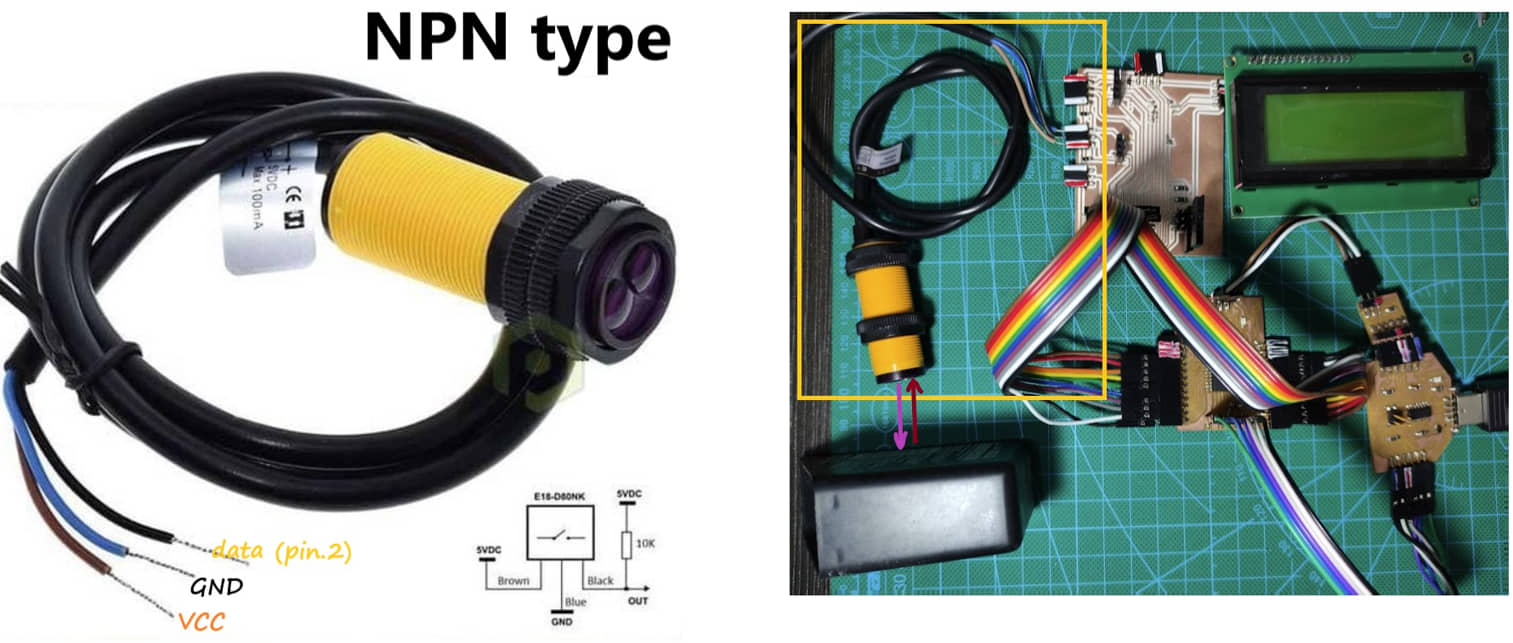
in this program I use the IR proximity sensor to detect any obstacles or objects in front of the sensor. The distance of the detected object can be adjusted by adjusting the screw on the back of the sensor. When there is an object in front of the sensor, the data will be sent to the MCU via pin.2 and shown on the LCD, serial monitor, and turn on the internal lights of the MCU pin.16. When the obstacle disappears, the sensor will notify the MCU and the light will turn off and show it on the LCD and serial monitor.
#include  <LiquidCrystal_I2C.h>
const int Pin=2;
const int ledPin = 16;

LiquidCrystal_I2C lcd(0x27, 20,4);  // I2C adress

void setup()
{

  pinMode(Pin, INPUT);
  pinMode(ledPin, OUTPUT);
  Serial.begin(115200);

  lcd.begin();
  lcd.backlight();
  delay(250);
  lcd.noBacklight();
  delay(250);
  lcd.backlight();

  lcd.setCursor(0,0);
  lcd.print("Fablab Kamakura");
  delay(1000);
  lcd.setCursor(0,1);
  lcd.print("Setyawan UGM");
  delay(2000);
  lcd.clear();
  lcd.setCursor(0,0);
  lcd.print("Proximity Sensor");
}

void loop()
{

  int sensorValue = digitalRead(Pin);
    if(sensorValue==1){
     digitalWrite(ledPin, LOW);
       lcd.setCursor(0,2);
       lcd.print("Box Empty");
        Serial.print("Proximity Sensor Status :");
        Serial.println("Full");
}
else
{
  digitalWrite(ledPin, HIGH);
        lcd.setCursor(0,2);
        lcd.print("Box Full");
        Serial.print("Proximity Sensor Status :");
        Serial.println("Empty");
}
  delay(200);

}
Gas Sensor
MQ02 Sensor
The MQ-2 module is a gas sensor to detect the content of flammable hydrocarbon gases such as isobutane (C4H10 / isobutane), propane (C3H8 / propane), methane (CH4 / methane), ethanol (ethanol alcohol, CH3CH2OH), hydrogen (H2 / hydrogen), smoke (smoke), and LPG (liquid petroleum gas). Datasheet of MQ-02 Sensor can be download here.
To do programming using this MQ02 sensor we need to first download the MQ-02 Library
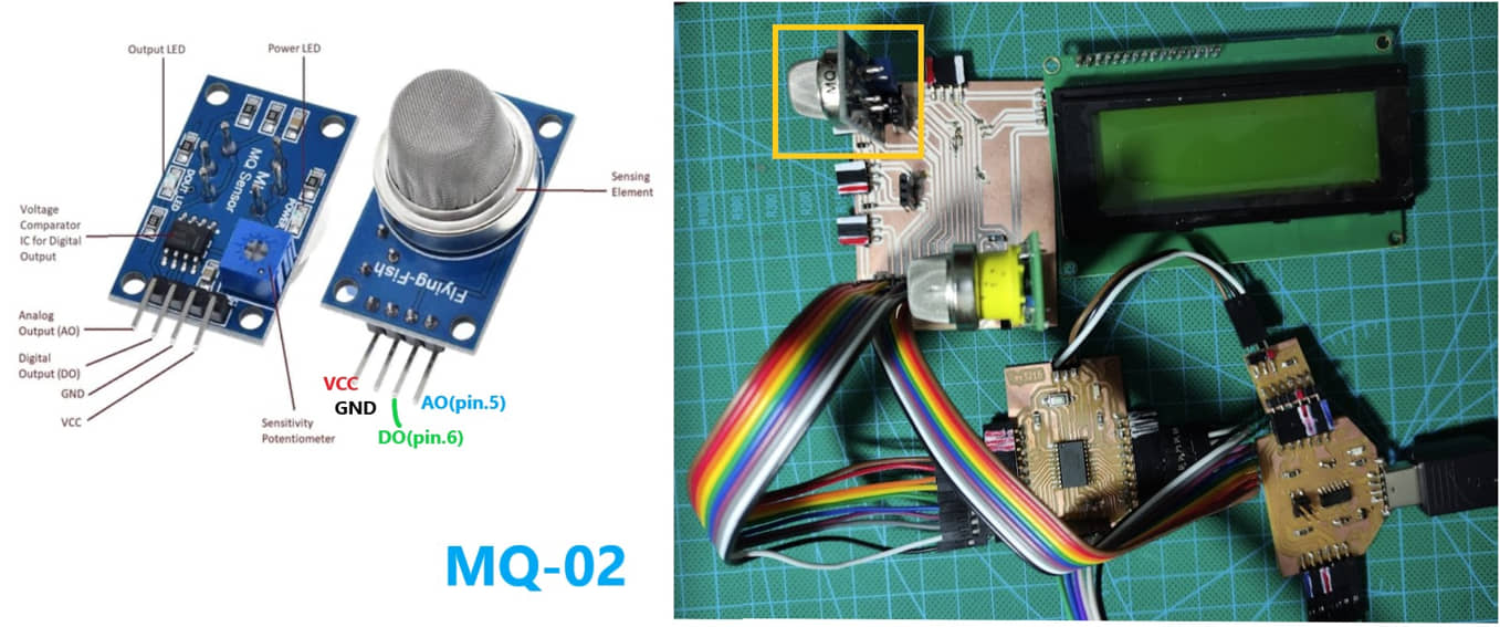
The program below is to access the MQ-02 sensor using the library. From the data obtained in the form of:
- LPG in ppm
- CO in ppm
- SMOKE in ppm
then the value is displayed on the LCD and serial monitor. To check, use a gas lighter (butane gas) that is emitted near the sensor. the result is an increase in the value of LPG.
#include <MQ2.h>
#include  <Wire.h>
#include  <LiquidCrystal_I2C.h>
LiquidCrystal_I2C lcd(0x27, 20,4);

//change this with the pin that you use
int pin = 5;
float lpg, co, smoke;

MQ2 mq2(pin);

void setup(){

  Serial.begin(115200);
  lcd.begin();
  lcd.backlight();
  delay(250);
  lcd.noBacklight();
  delay(250);
  lcd.backlight();

  lcd.setCursor(0,0);
  lcd.print("Fablab Kamakura");
  delay(1000);
  lcd.setCursor(0,1);
  lcd.print("Setyawan UGM");
  delay(2000);
      lcd.clear();
  // calibrate the device
  mq2.begin();
}

void loop(){

  /*
   * read the values from the sensor, it returns
   * an array which contains 3 values.
   * 0 : LPG in ppm
   * 1 : CO in ppm
   * 2 : SMOKE in ppm
   */
  float* values= mq2.read(true); //set it false if you don't want to print the values to the Serial

  // lpg = values[0];
  lpg = mq2.readLPG();
   lcd.setCursor(0,0);
  lcd.print("LPG(ppm)  :");
  lcd.setCursor(11,0);
  lcd.print(lpg);

  // co = values[1];
  co = mq2.readCO();
    lcd.setCursor(0,1);
  lcd.print("CO(ppm)   :");
  lcd.setCursor(11,1);
  lcd.print(co);

  // smoke = values[2];
  smoke = mq2.readSmoke();
  lcd.setCursor(0,2);
  lcd.print("Smoke(ppm):");
  lcd.setCursor(11,2);
  lcd.print(smoke);
   delay(1000);
}
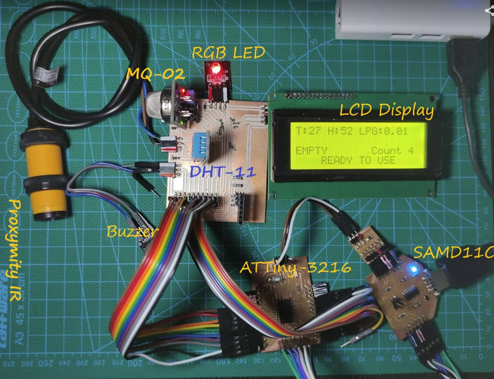
Integrated Sensors
In this section I will try to integrate several sensors and output devices that will describe the general system in my final project. Some of the devices that I will use include:
- DHT-11 . sensor
- MQ-02 . sensor
- IR Proximity sensor
- LCD display 20x4 I2C
- Buzzer
- RGB LED
The working principle is as follows:
- at idle, the LED will light up red, the LCD will monitor the temperature, humidity and LPG gas content (this will also be displayed on the serial monitor)
- when there is an obstacle in front of the proximity sensor, the LED turns green, the status on the LCD becomes: “IN USE”,
- if the obstacle goes/disappears from the front of the sensor, the counter will count (add one), turn on the buzzer and the blue LED will flash (this condition will be used to drive the motor in the next development program)
- every time there is an obstacle and the obstacle leaves the sensor, it will conting and turn on the buzzer mechanism.
- Likewise, if the LPG gas sensing exceeds a certain value (>2), there will be a mechanism to turn on the buzzer.
- after the buzzer mechanism, the display shows temperature, humidity, LPG consentration, number of uses (count) and the description “Ready to Use”.
#include  <Wire.h>
#include  <LiquidCrystal_I2C.h>
#include <DFRobot_DHT11.h>
#include <MQ2.h>
DFRobot_DHT11 DHT;
LiquidCrystal_I2C lcd(0x27, 20,4);  // I2C adress
#define DHT11_PIN 3

const int IRPin=2;
const int ledPin = 16;
const int ledPinG = 10;
const int ledPinB = 12;
const int BuzPin = 1;
const int pin = 5;
int sensorValue = 0;
int prestate = 0;
int count=0;
int stat=0;
float lpg, co, smoke;
MQ2 mq2(pin);


void setup()
{
  Serial.begin(115200);
  pinMode(IRPin, INPUT);
  pinMode(ledPin, OUTPUT);
  pinMode(ledPinG, OUTPUT);
  pinMode(ledPinB, OUTPUT);
  pinMode(BuzPin, OUTPUT);

  mq2.begin();
  lcd.begin();
  lcd.backlight();
  delay(250);
  lcd.noBacklight();
  delay(250);
  lcd.backlight();
  lcd.setCursor(0,0);
  lcd.print("Fablab Kamakura");
  delay(1000);
  lcd.setCursor(0,1);
  lcd.print("Setyawan UGM");
  delay(2000);
  lcd.clear();
 // digitalWrite(BuzPin, HIGH);
}

void loop()
{
  DHT.read(DHT11_PIN);


  Serial.print("temperature:");
  Serial.print(DHT.temperature);
//  Serial.print(char(176));
  Serial.println("\u00b0 C");
  Serial.print("humidity :");
  Serial.print(DHT.humidity);
  Serial.println("%");
  lcd.setCursor(0,0);
  lcd.print("T:");
  lcd.setCursor(2,0);
  lcd.print(DHT.temperature);
  lcd.setCursor(5,0);
  lcd.print("H:");
  lcd.setCursor(7,0);
  lcd.print(DHT.humidity);

  float* values= mq2.read(true);
  lpg = mq2.readLPG();
  lcd.setCursor(10,0);
  lcd.print("LPG:");
  lcd.setCursor(14,0);
  lcd.print(lpg);
         lcd.setCursor(4,3);
        lcd.print("READY TO USE");

    sensorValue = digitalRead(IRPin);
    if(sensorValue==0){
          lcd.clear();
      if (count==stat){
             count++;
      }
       digitalWrite(ledPin, HIGH);
       digitalWrite(ledPinG, HIGH);
       digitalWrite(ledPinB, LOW);
       lcd.setCursor(0,2);
       lcd.print("IN USE");
       Serial.print("Status :");
       Serial.println("Full");
       Serial.println();
       prestate = 1;

    }
    else
    {
       digitalWrite(ledPin, LOW);
       digitalWrite(ledPinB, LOW);
       digitalWrite(ledPinG, LOW);
       lcd.setCursor(0,2);
       lcd.print("EMPTY ");
       Serial.print("Status :");
       Serial.println("Empty");
       Serial.println();
       stat = count;
       if (prestate == 1||lpg>2){
        for (int i=1; i<=10; i++) {
        digitalWrite(BuzPin, HIGH);
        digitalWrite(ledPinB, HIGH);
        delay(500);
        digitalWrite(BuzPin, LOW);
        digitalWrite(ledPinB, LOW);
        delay(700);
        lcd.setCursor(2,3);
        lcd.print("CHANGE THE LITTER");

        }
        lcd.clear();
       }
       prestate = 0;

}
 lcd.setCursor(12,2);
 lcd.print("Count");
 lcd.setCursor(18,2);
 lcd.print(count);

}
Result (Hero Video):
References
- Kamakura : Week 12 - Input Device
- Input Devices - Kamakura local session
- DHT sensor library
- How HC-SR04 Ultrasonic Sensor Works
- Manish J. Gajjar, in Mobile Sensors and Context-Aware Computing, 2017
Documentation Files
- DHT program (.ino)
- Proximity IR program (.ino)
- Photoresistor LDR program (.ino)
- Distance Ultrasonic SR-04 program (.ino)
- Gas MQ-02 program (.ino)
- integration sensor program (.ino)
- Sensor Board trace(.svg)
- Sensor Board interior(.svg)
- Visualization data with python (.py)
- Sensor Board KiCAD Project (.zip)
Group assignment learning
- In the group assignment, we measure the signal of input device
- Understanding the type of signal at input device
Lessons learned (week 12 : Input Device):
- Understanding of MCU pin assignment as input ATtiny 3216)
- Understanding several type of sensors, the function and how to choose it
- Understand how to program the input device (sensor) for ATtiny (Analog and Digital type)
- Understanding algorithm to integrated several input device