13. Networking and communications
Week 13 : To do checklist
- Learn about type and protocol of communications and networking
- Individual Practice
- make the “hub” for I2C communication
- Programming MCU using I2C, SPI, and UART protocol for communication several devices
- try for wireless communication programming
- Group work
- Make program and test for communication between two devices
- Repo to push group work (Kamakura) 2022
- Continue the final Project Process
- Documentations
Assignment (week 13):
Individual assignment:
- design, build, and connect wired or wireless node(s) with network or bus addresses
Group assignment:
- Send a message between two projects
This week I worked on Networking and communications
Please click the button for Group Assignment
Wired - Serial Communications
There are several types of Serial Communication used in microcontrollers, including: 1-Wire, UART, JTAG, I2C, SPI, USB, RS-232, MIDI , SBUS, PPM, CAN. Each communication model has its own protocol and characteristics.
In this week’s assignment I tried a few that are widely used today. General comparison of several types of communication that are widely used:
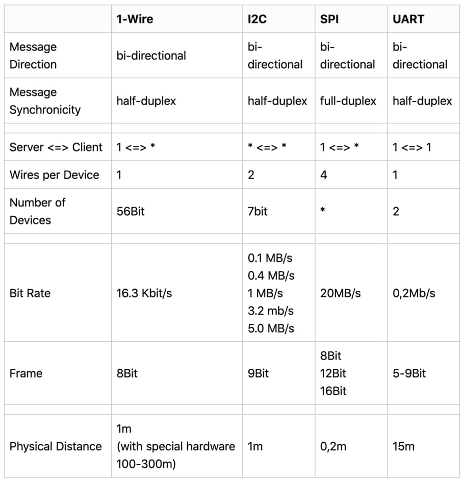
source : http://electronoobs.com/
I2C (Inter-Integrated Circuit)
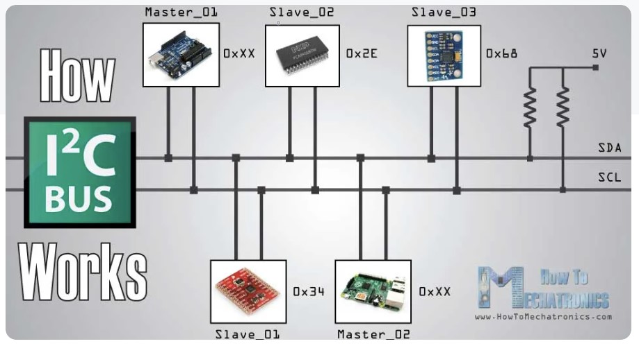
I2C stands for Inter Integrated Circuit, is a protocol for serial communication between ICs, and is often called Two Wire Interface TWI. Buses are used for communication between the microcontroller and peripheral devices such as memory, temperature sensors, and IO expanders.
Two channels/buses in serial communication are known as SCL and SDA. SCL / Serial clock serves to synchronize the existing data between the master and slave. Meanwhile, SDA/Serial Data functions as a data channel.
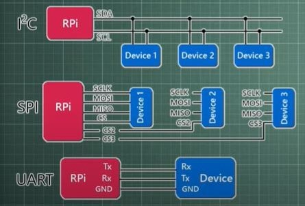
source : https://howtomechatronics.com/
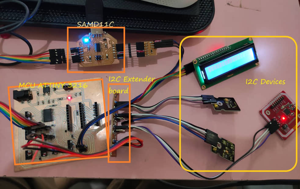
I am trying to communicate between Attiny MCU (as master) with some devices using I2C protocol. Some of these devices include:
- LCD Display with I2C
- Proximity Detection Module (Ks0269 keyestudio TMD27713)
- Digital Acceleration Tilt Sensor (Ks0270 keyestudio MMA8452Q)
- NFC RFID PN532
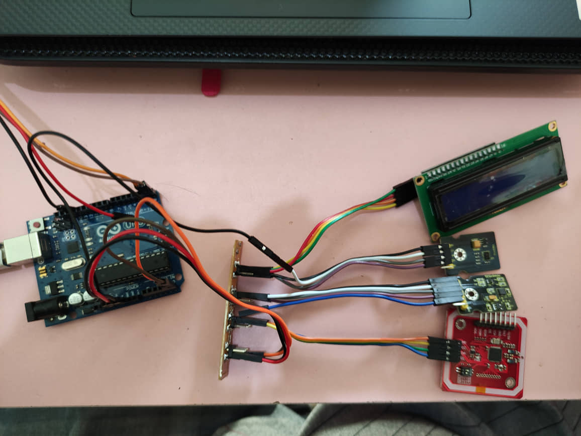
Previously I made a PCB for an I2C extender, so that it can be used for several devices at once.
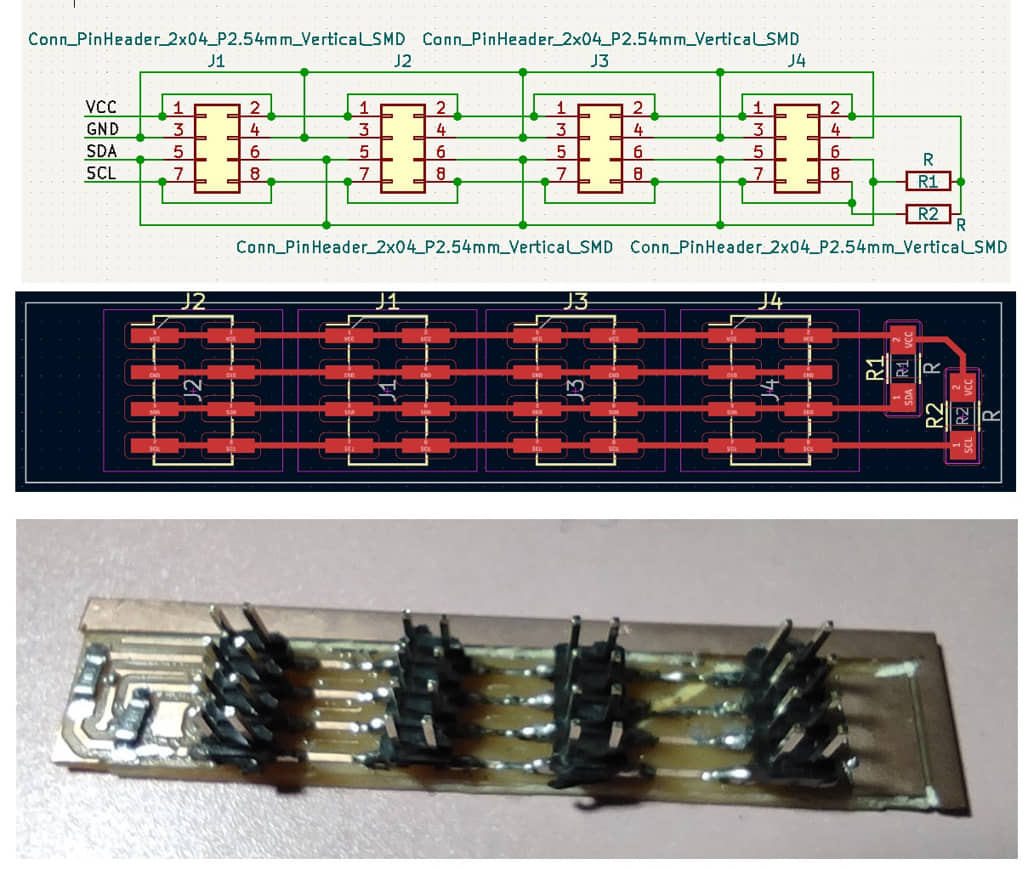
After the PCB was finished, I connect several devices that use I2C communication on the I2C extender board as shown in the following picture.
Before doing I2C programming, I tried to scan connected devices via the I2C extender board using the I2C scanning program as in week 10
Scan results can be seen in the following image
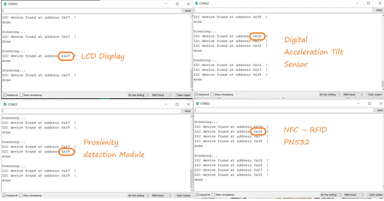
In all connected conditions, I tried to access the existing I2C devices one by one.
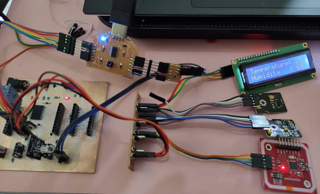
LCD Display
As in the previous week’s task, the LCD can be used to display the results of data processing using ATTiny 3216. The program used as an example is to display the DHT11 sensor (one wire).
#include  <Wire.h>
#include  <LiquidCrystal_I2C.h>
#include <DFRobot_DHT11.h>
DFRobot_DHT11 DHT;
#define DHT11_PIN 3

LiquidCrystal_I2C lcd(0x27, 16,2);  // Ganti 0x3F dengan address I2C anda

void setup()
{
  Serial.begin(115200);
  lcd.begin();
  lcd.backlight();
  delay(250);
  lcd.noBacklight();
  delay(250);
  lcd.backlight();
  lcd.setCursor(0,0);
  lcd.print("Fablab Kamakura");
  delay(1000);
  lcd.setCursor(0,1);
  lcd.print("Setyawan UGM");
  delay(3000);
      lcd.clear();
}

void loop()
{
  DHT.read(DHT11_PIN);
  Serial.print("temp:");
  Serial.print(DHT.temperature);
  Serial.print("  humi:");
  Serial.println(DHT.humidity);
  lcd.setCursor(0,0);
  lcd.print("Temperature:");
  lcd.setCursor(13,0);
  lcd.print(DHT.temperature);
  lcd.setCursor(0,1);
  lcd.print("Humidity   :");
  lcd.setCursor(13,1);
  lcd.print(DHT.humidity);
  delay(1000);
}
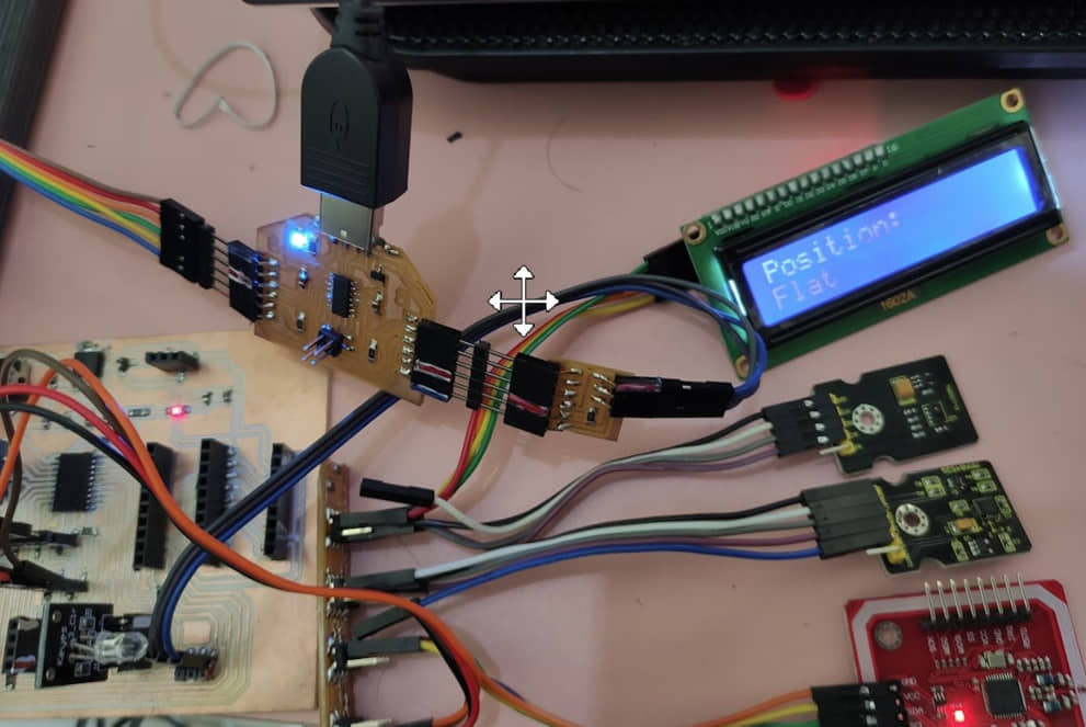
Digital Acceleration Tilt Sensor
MMA8452Q is a smart low-power, three-axis, capacitive micromachine acceleration sensor with 12-bit resolution. This acceleration sensor has a rich embedded performance, featured with flexible user programmable options and two interruption pins configuration. The embedded interruption function can save the overall power consumption and remove the burden of constantly polling the data in the main processor (keyestudio).
This program is used to detect the tilt of the sensor in either the x-axis or y-axis direction. We can put this sensor on an object that we will detect the slope of, so that when the object changes its slope it will be detected by the sensor. The library of SparkFun_MMA8452Q can be download here
#include <Wire.h> // Must include Wire library for I2C
#include <SparkFun_MMA8452Q.h> // Includes the SFE_MMA8452Q library
#include  <LiquidCrystal_I2C.h>
MMA8452Q accel;

LiquidCrystal_I2C lcd(0x27, 16,2);

void setup()
{
  Serial.begin(9600);
  Serial.println("MMA8452Q Test Code!");
  accel.init();
  lcd.begin();

  lcd.setCursor(0,0);
  lcd.print("Fablab Kamakura");
  delay(1000);
  lcd.setCursor(0,1);
  lcd.print("Setyawan UGM");
  delay(3000);
  lcd.clear();
}
void loop()
{
  if (accel.available())
  {
    accel.read();
    printCalculatedAccels();
    printOrientation();

    Serial.println(); // Print new line every time.
  }
}

void printAccels()
{
  Serial.print(accel.x, 3);
  Serial.print("\t");
  Serial.print(accel.y, 3);
  Serial.print("\t");
  Serial.print(accel.z, 3);
  Serial.print("\t");
}

void printCalculatedAccels()
{
  Serial.print(accel.cx, 3);
  Serial.print("\t");
  Serial.print(accel.cy, 3);
  Serial.print("\t");
  Serial.print(accel.cz, 3);
  Serial.print("\t");
}

// This function demonstrates how to use the accel.readPL()
// function, which reads the portrait/landscape status of the
// sensor.
void printOrientation()
{
  // accel.readPL() will return a byte containing information
  // about the orientation of the sensor. It will be either
  // PORTRAIT_U, PORTRAIT_D, LANDSCAPE_R, LANDSCAPE_L, or
  // LOCKOUT.
  byte pl = accel.readPL();
  lcd.clear();
  switch (pl)
  {
  case PORTRAIT_U:
    Serial.print("Portrait Up");
    lcd.setCursor(0,0);
    lcd.print("Position:");
    lcd.setCursor(0,1);
    lcd.print("Portrait Up");
    delay(200);
    break;
  case PORTRAIT_D:
    Serial.print("Portrait Down");
    lcd.setCursor(0,0);
    lcd.print("Position:");
    lcd.setCursor(0,1);
    lcd.print("Portrait Down");
    delay(200);
    break;
  case LANDSCAPE_R:
    Serial.print("Landscape Right");
    lcd.setCursor(0,0);
    lcd.print("Position:");
    lcd.setCursor(0,1);
    lcd.print("Landscape Right");
    delay(200);
    break;
  case LANDSCAPE_L:
    Serial.print("Landscape Left");
    lcd.setCursor(0,0);
    lcd.print("Position:");
    lcd.setCursor(0,1);
    lcd.print("Landscape Left");
    delay(200);
    break;
  case LOCKOUT:
    Serial.print("Flat");
    lcd.setCursor(0,0);
    lcd.print("Position:");
    lcd.setCursor(0,1);
    lcd.print("Flat");
    delay(200);

    break;
  }
}
Proximity Detection Module & NFC RFID PN532
When compiling these two modules, the library used does not support to ATTiny 3216. Even though when scanning, I2C addresses can be detected, but the program accesses cannot be used. So finally I tried to use Arduino Uno to access these two modules.
Proximity Detection Module
Tests the proximity interrupt abilities of the APDS-9930. The library of APDS9930 can be download here
#define DUMP_REGS
#define PWM_LED_PIN       10
#include  <LiquidCrystal_I2C.h>
#include <Wire.h>
#include <APDS9930.h>
LiquidCrystal_I2C lcd(0x27, 16,2);
// Global Variables
APDS9930 apds = APDS9930();
uint16_t proximity_data = 0;
int proximity_max = 0;

void setup() {
  //analogReference(EXTERNAL);
  pinMode(PWM_LED_PIN, OUTPUT);

  // Initialize Serial port
  Serial.begin(9600);
    lcd.begin();
  Serial.println();
  Serial.println(F("------------------------"));
  Serial.println(F("APDS-9930 - ProximityLED"));
  Serial.println(F("------------------------"));

  // Initialize APDS-9930 (configure I2C and initial values)
  if ( apds.init() ) {
    Serial.println(F("APDS-9930 initialization complete"));
  } else {
    Serial.println(F("Something went wrong during APDS-9930 init!"));
  }

  // Adjust the Proximity sensor gain
  if ( !apds.setProximityGain(PGAIN_1X) ) {
    Serial.println(F("Something went wrong trying to set PGAIN"));
  }

  // Start running the APDS-9930 proximity sensor (no interrupts)
  if ( apds.enableProximitySensor(false) ) {
    Serial.println(F("Proximity sensor is now running"));
  } else {
    Serial.println(F("Something went wrong during sensor init!"));
  }

#ifdef DUMP_REGS
  /* Register dump */
  uint8_t reg;
  uint8_t val;

  for(reg = 0x00; reg <= 0x19; reg++) {
    if( (reg != 0x10) && \
        (reg != 0x11) )
    {
      apds.wireReadDataByte(reg, val);
      Serial.print(reg, HEX);
      Serial.print(": 0x");
      Serial.println(val, HEX);
    }
  }
  apds.wireReadDataByte(0x1E, val);
  Serial.print(0x1E, HEX);
  Serial.print(": 0x");
  Serial.println(val, HEX);
#endif
}

void loop() {

  // Read the proximity value
  if ( !apds.readProximity(proximity_data) ) {
    Serial.println("Error reading proximity value");
  } else {
    Serial.print("Proximity: ");
    Serial.print(proximity_data);

    // This is an ugly hack to reduce sensor noise.
    // You may want to adjust POFFSET instead.
    /*
    proximity_data -= 200;
    if (proximity_data > 50000) {
      proximity_data = 0;
    }
    if (proximity_data > proximity_max) {
      proximity_max = proximity_data;
    }
    proximity_data = map(proximity_data, 0, proximity_max, 0, 1023);
    */

    Serial.print(F("  Remapped: "));
    Serial.println(proximity_data);
    analogWrite(PWM_LED_PIN, proximity_data);
    if (proximity_data<100)
    {
       lcd.setCursor(0,0);
       lcd.print("ON");
       delay(200);
       lcd.clear();
    }
   else {
       lcd.setCursor(0,0);
       lcd.print("OFF");
       delay(200);
       lcd.clear();
   }
  }

  // Wait 250 ms before next reading
  delay(10);
}
NFC RFID PN532
Near Field Communication (NFC) is a technology standard based on Radio Frequency Identification (RFID), transmitting information wirelessly over short distances. NFC operates on the principle of inductive coupling, at least for short-range implementations. This essentially involves the reader device generating a magnetic field by passing an electric current through a coil. When a tag (with its own coil) is brought nearby, the field induces an electric current within the tag — sans any wires or even physical contact. Then, once the initial handshake is complete, any stored data on the tag is wirelessly transmitted to the reader. (source :how2electronics.com)
In this program we will try to access the PN532 module to detect the RFID card and read it on the serial monitor. The library of PN532 can be download here
#include <Wire.h>
#include <PN532_I2C.h>
#include <PN532.h>
#include <NfcAdapter.h>
PN532_I2C pn532_i2c(Wire);
NfcAdapter nfc = NfcAdapter(pn532_i2c);
String tagId = "None";
byte nuidPICC[4];

void setup(void)
{
 Serial.begin(115200);
 Serial.println("System initialized");
 nfc.begin();
}

void loop()
{
 readNFC();
}

void readNFC()
{
 if (nfc.tagPresent())
 {
   NfcTag tag = nfc.read();
   tag.print();
   tagId = tag.getUidString();
 }
 delay(5000);
}
SPI
Serial Peripheral Interface (SPI) is a synchronous serial data protocol used by microcontrollers to communicate with one or more short-range fast peripheral devices. It can also be used for communication between two microcontrollers. With an SPI connection there is always a single master device (usually a microcontroller) that controls the peripheral devices.
There are three main lines of SPI are as follows:
- MOSI : Master Output Slave Input It means that if configured as master then MOSI pin as output but if configured as slave then MOSI pin as input.
- MISO : Master Input Slave Output It means that if configured as master then MISO pin as input but if configured as slave then MISO pin as output.
- CLK : Clock If configured as master then CLK pin acts as output but if configured as slave then CLK pin acts as input.
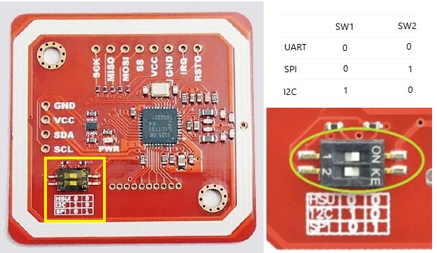
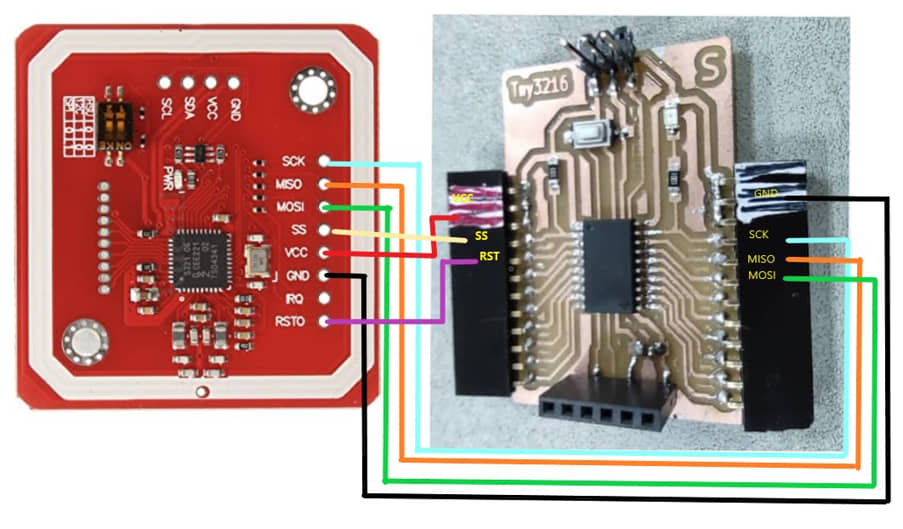
The PN532 NFC RFID Module also has a communication protocol using SPI. to select the type of protocol used we need to select the configuration of the switches found on the board. In using the SPI protocol we can use the following program:
// for SPI Communication
#include <SPI.h>
#include <PN532_SPI.h>
#include <PN532.h>
#include <NfcAdapter.h>
PN532_SPI interface(SPI, 0); // create a PN532 SPI interface with the SPI CS terminal located at digital pin 10
NfcAdapter nfc = NfcAdapter(interface); // create an NFC adapter object
String tagId = "None";

void setup(void)
{
 Serial.begin(115200);
 Serial.println("System initialized");
 nfc.begin();
}

void loop()
{
 readNFC();
}

void readNFC()
{
 if (nfc.tagPresent())
 {
   NfcTag tag = nfc.read();
   tag.print();
   tagId = tag.getUidString();
 }
 delay(5000);
}
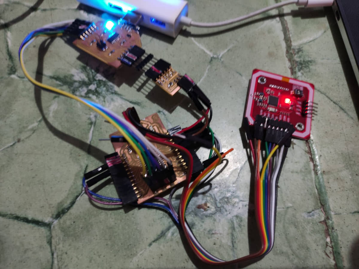
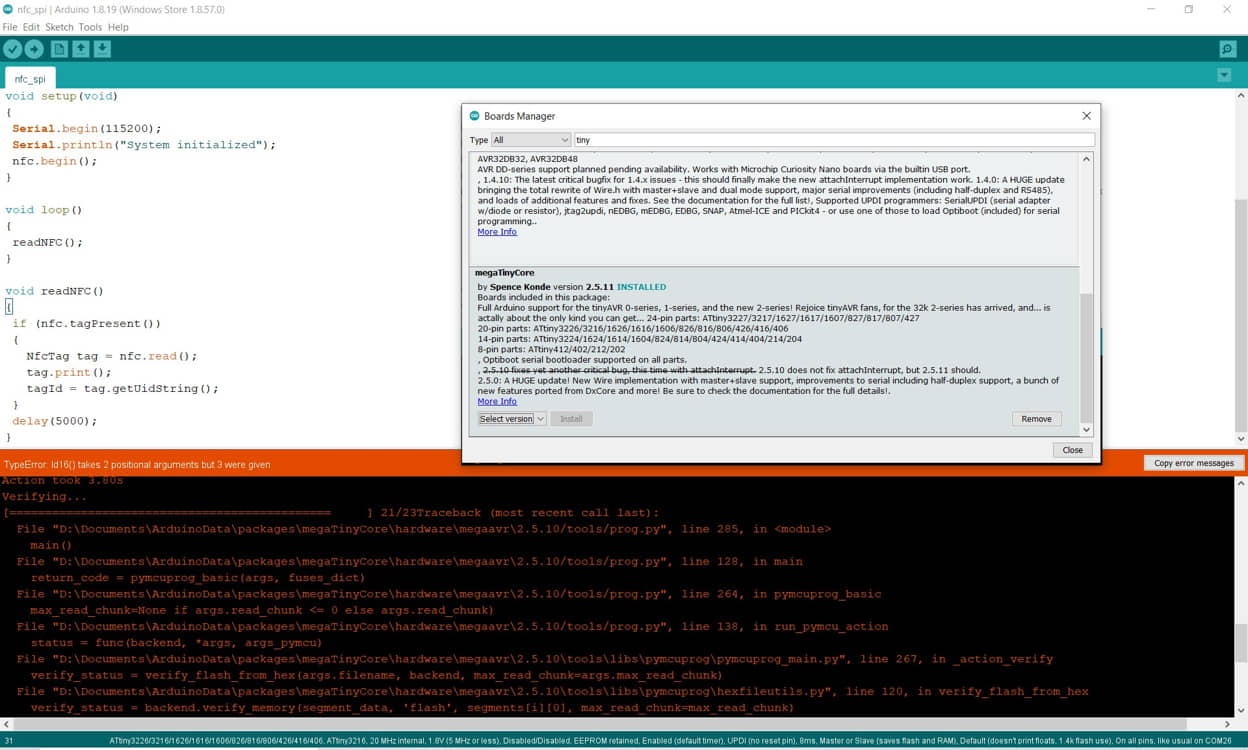
when running this program compile sketch for attiny3216 an error occurred as shown. Then I tried to update the board manager for MegaTinyCore to version 2.5.11.
After the update I tried to compile and upload the sketch again, and it worked. After that I tried to see the results on the serial monitor. It takes a long time (about 30 seconds) to be read on the serial monitor and can read the RFID card. Furthermore, it can work as in the program with SPI.
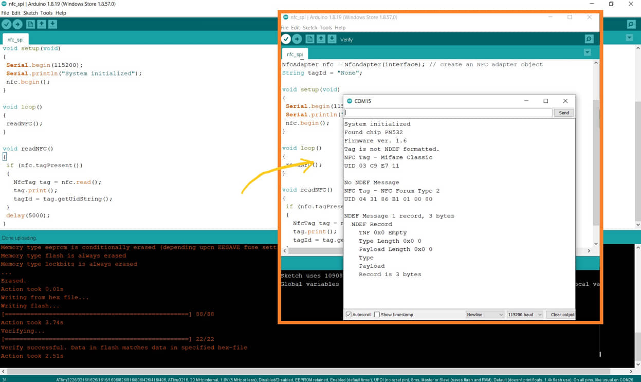
Comment : Using NFC RFID Sensor PN532 using AT-Tinny 3216
The PN532 module is a module that can read (and write) NFC/RFID tags. The PN532 module has three alternative communication ports, namely SPI (Serial Perpheral Interface), I2C (Inter-Integrated Circuit) and HSU (High Speed UART). we can choose one of the communication models to be used.
When using this sensor with the ATtiny 3216 MCU initially it didn’t work for all types of communication, always an error occurred. This is because the library used does not support the Attiny 3216 MCU. So I tried to use Arduino Uno. When using Arduino UNO communication and sensor readings can work (library support on Arduino Uno).
When I checked on the latest ATtiny board manager (ver. 2.5.11) it turned out that there was an improvement in the SPI communication system, so I took the initiative to update the Arduino IDE.
The result after I tried to communicate with this sensor using SPI communication ..... it worked. But for other communications using Attiny has not been successful.
UART
UART or Universal Asynchronous Receiver Transmitter is a communication protocol that is commonly used in sending serial data between devices. For example, communication between fellow microcontrollers or microcontrollers to a PC. In sending data, the clock between the sender and receiver must be the same because the data packets sent each bit rely on the clock.
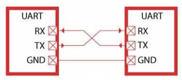
I’m trying to make a simple program for communication via UART using the Arduino MCU and ATTiny 3216. The two systems are connected via a serial port in a cross manner.
I uploaded a sketch to send data to the serial port on the Arduino uni as a transceiver. and on Attiny I upload a sketch to receive data from the serial and display it on the serial monitor
Program on transceiver (Arduino Uno)
void setup() {
  Serial.begin(9600);
 }
void loop() {
  Serial.print("Serial Communication");
  delay(500);
}
Program on Receiver (ATtiny3216)
String data;
void setup() {
 Serial.begin(9600);
}
void loop() {
  while(Serial.available()>0){
    delay(10);
    char c = Serial.read();
    data+=c;
  }
  if(data.length()>0){
    Serial.println(data);
    data="";
  }
}
other program for serial communication
I am trying to compile a program to access the proximity sensor (using I2C communication, like the above program) using Arduino, then the data from the proximity is sent to the serial port. If an object is detected, it will define the value “1” while if there is no object it will be “0”. While the other MCU (attiny 3216) will detect serial data from the serial port. If the serial data is “1” it will turn on the LED on ATTiny and if it is “0” it will turn off the LED.
#define DUMP_REGS
#define PWM_LED_PIN       10
#include  <LiquidCrystal_I2C.h>
#include <Wire.h>
#include <APDS9930.h>
LiquidCrystal_I2C lcd(0x27, 16,2);
// Global Variables
APDS9930 apds = APDS9930();
uint16_t proximity_data = 0;
int proximity_max = 0;

void setup() {
  //analogReference(EXTERNAL);
  pinMode(PWM_LED_PIN, OUTPUT);

  // Initialize Serial port
  Serial.begin(9600);
    lcd.begin();
 // Serial.println();
 // Serial.println(F("------------------------"));
 // Serial.println(F("APDS-9930 - ProximityLED"));
 // Serial.println(F("------------------------"));

  // Initialize APDS-9930 (configure I2C and initial values)
  if ( apds.init() ) {
 //   Serial.println(F("APDS-9930 initialization complete"));
  } else {
 //   Serial.println(F("Something went wrong during APDS-9930 init!"));
  }

  // Adjust the Proximity sensor gain
  if ( !apds.setProximityGain(PGAIN_1X) ) {
  //  Serial.println(F("Something went wrong trying to set PGAIN"));
  }

  // Start running the APDS-9930 proximity sensor (no interrupts)
  if ( apds.enableProximitySensor(false) ) {
 //   Serial.println(F("Proximity sensor is now running"));
  } else {
  //  Serial.println(F("Something went wrong during sensor init!"));
  }

#ifdef DUMP_REGS
  /* Register dump */
  uint8_t reg;
  uint8_t val;

  for(reg = 0x00; reg <= 0x19; reg++) {
    if( (reg != 0x10) && \
        (reg != 0x11) )
    {
      apds.wireReadDataByte(reg, val);
   //   Serial.print(reg, HEX);
   //   Serial.print(": 0x");
    //  Serial.println(val, HEX);
    }
  }
  apds.wireReadDataByte(0x1E, val);
 // Serial.print(0x1E, HEX);
 // Serial.print(": 0x");
 // Serial.println(val, HEX);
#endif
}

void loop() {

  // Read the proximity value
  if ( !apds.readProximity(proximity_data) ) {
 //   Serial.println("Error reading proximity value");
  } else {
 //   Serial.print("Proximity: ");
  //  Serial.print(proximity_data);

    // This is an ugly hack to reduce sensor noise.
    // You may want to adjust POFFSET instead.

//    Serial.print(F("  Remapped: "));
//    Serial.println(proximity_data);
    analogWrite(PWM_LED_PIN, proximity_data);
    lcd.clear();
    if (proximity_data>200)
    {

      Serial.print("1");
       lcd.setCursor(0,0);
       lcd.print("ON");
       delay(200);

   }
   else {
    Serial.print("0");
           lcd.setCursor(0,0);
       lcd.print("OFF");
       delay(200);
   }
  }
  delay(10);
}
for receiver
int ledR = 11;
int ledG = 12;
int ledB = 13;
String data;

void setup() {
 Serial.begin(9600);
 pinMode(ledR, OUTPUT);
 pinMode(ledG, OUTPUT);
 pinMode(ledB, OUTPUT);
 digitalWrite(ledG, LOW);    // turn the LED off by making the voltage LOW
    delay(1000);
}
void loop() {
  while(Serial.available()>0){
    delay(100);
    char data = Serial.read();
 //   data+=c;
    Serial.println(data);
    if(data == '1'){
    digitalWrite(ledG, HIGH);
    digitalWrite(ledR, LOW);
    digitalWrite(ledB, LOW);
    }
    else {
    digitalWrite(ledG, LOW);
    digitalWrite(ledR, HIGH);
    digitalWrite(ledB, LOW);

    }
  }
}
Wireless
Bluetooth
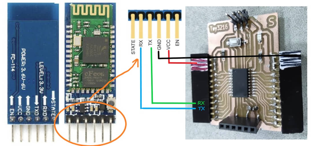
Another communication I have tried is using wireless. In this task I use the bluetooth module hc-05. This module communicates to the MCU using the UART protocol. I will make a program to turn on the RGB lights on the MCU (attiny3216) with control from a smartphone. Some steps that need to be done are:
- attach the HC-05 module by connecting the RX pin (hc-05) TX (MCU), and the TX pin (hc-05) to the RX leg (MCU) -upload the following program sketch to the MCU
- on the smartphone we need to install from the playstore “arduino bluetooth controller”
- HC-05 bluetooth pairing with smartphone
- run the arduino bluetooth controller application on the BUTTON menu
- defined: button 1 (on: 1, off:4), button 1 (on: 2, off:5), button 3 (on: 3, off:6)
- press button 1, 2 or 3 on the application to turn on the RGB led.
int ledR = 11;
int ledG = 12;
int ledB = 13;
String data;

void setup() {
  Serial.begin(9600);
  pinMode(ledR, OUTPUT);
  pinMode(ledG, OUTPUT);
  pinMode(ledB, OUTPUT);
  digitalWrite(ledG, LOW);
  digitalWrite(ledR, LOW);
  digitalWrite(ledB, LOW);
  delay(1000);
}
void loop() {
  while (Serial.available() > 0) {
    delay(100);
    char data = Serial.read();
    //   data+=c;
    Serial.println(data);
    if (data == '1') {
      digitalWrite(ledR, HIGH);
    }
    else if (data == '2') {
      digitalWrite(ledG, HIGH);
    }
    else if (data == '3') {
      digitalWrite(ledB, HIGH);
    }
    else if (data == '4') {
      digitalWrite(ledR, LOW);
    }
    else if (data == '5') {
      digitalWrite(ledG, LOW);
    }
    else if (data == '6') {
      digitalWrite(ledB, LOW);

    }
  }
}
The Test and Result
comment :
This Bluetooth can be used as a wireless connection between two systems such as an MCU with a Smartphone. The advantage of being wireless is that you can still be connected without the hassle of cables. We can control the system on the MCU with a smartphone so that it becomes practical. Very interesting !!!
Some of the tests on reading the sensor apart from what I did with the At-tiny 3216 development board that I made the previous week. Also I do with MCU Attiny 3216 which I have customized for my final project needs. to try a functional PCB for FP.
Conculsion :
What I learned : To read a sensor (input devices) or actuator (output devices) then I have to know the communication model used (SPI, I2C, UART, One wire, Digital, Analog) so that the MCU has the communication.
On devices with libraries for communication sometimes do not support certain types of MCU. Usually the Arduino type is more common and is widely supported by various libraries. so using Arduino to test communication and programming/debugging devises is more convincing. Only after successful can be tried for other types of MCU.
References
- Kamakura : Week 13 - Networking and communications
- Input Devices - Kamakura local session
- Wired Communication Protocols in Embedded Design
- Interfacing PN532 NFC RFID Module with Arduino
- Manish J. Gajjar, in Mobile Sensors and Context-Aware Computing, 2017
Documentation Files
- Bluetooth (.ino)
- LCD I2C with DHT11 Sensor (.ino)
- Tranceiver Serial TX (.ino)
- Receiver Serial RX (.ino)
- Digital Acceleration Tilt Sensor (.ino)
- I2C extender board trace(.svg)
- I2C extender board interior(.svg)
- I2C extender board KiCAD Project (.zip)
- Board for FP test KiCAD Project (.zip)
Group assignment learning
- In the group assignment, we connect several project (MCU)
- Understanding the types and protocols of communication between two device MCU
Lessons learned (week 13 : Networking and communications):
- Understanding of MCU communications type and protocol
- Understanding how to access the device with I2C, SPI and UART communication
- Understand how to used some wireless communication (bluetooth)
- Understanding algorithm to integrated several device with communication protocol.