11. Mechanical Design & Machine design
Week 11 : To do checklist
- Group work (individual contributions)
- Team discussion about the design machine concept that will be made
- Making mechanical designs
- Planning and supply of necessary materials
- Drive system planning (linear system)
- Printing/Milling components of mechanical building
- Helping electronic device development
- Equipment assembly
- Debugging and testing
- Repo to push group work (Kamakura) 2022
- Continue the final Project Process
- Documentations
Assignment (week 11):
Group assignment:
-
Mechanical Design
- design a machine that includes mechanism+actuation+automation+application
- build the mechanical parts and operate it manually
- document the group project and your individual contribution
-
Mechine Design
- actuate and automate your machine
- document the group project and your individual contribution
This week I worked on Mechanical Design & Machine design
Please click the button for Group Assignment
In this week’s assignment we will create machine for Automatic Filling Beverages.
This machine functions to mix several drinks (traditional drinks) automatically based on the desired type of drink.
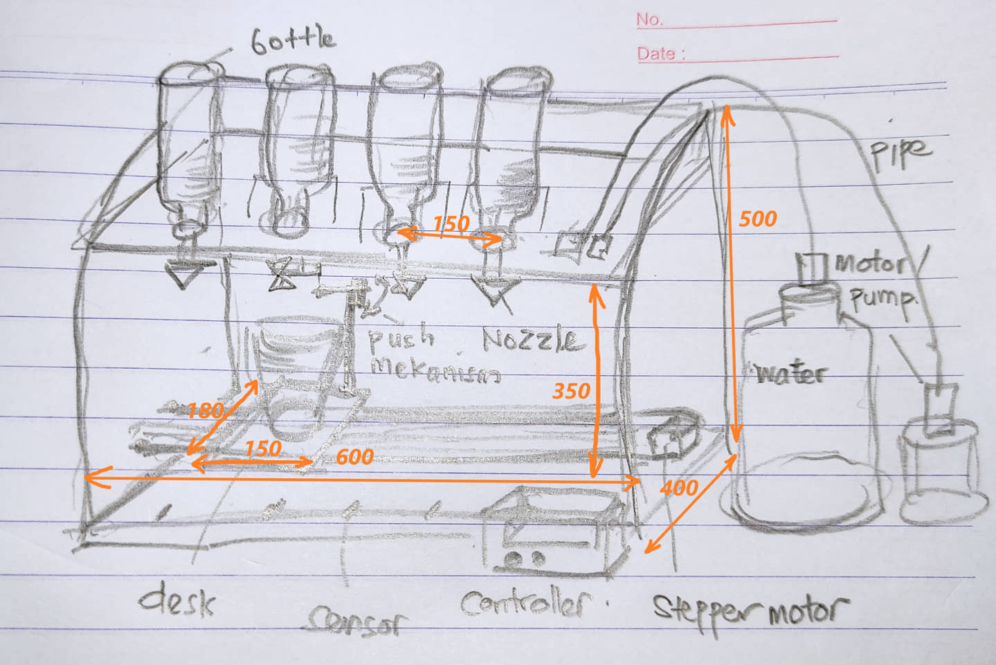
The machine consists of a machine body made using MDF board, at the top there is a place to put a bottle of beverage sources, in the middle there is a table where a glass can be placed that can be shifted with an automatic drink bottle opening mechanism and a controller on the front for orders for taking the type of drink along with sensors. required.
Based on the distribution of this machining contribution, I work on the design and production of the main body, construction, assembly
Based on sketch we define in Group assignment, I try to specific the dimensions:
To do this part there are several things I do are:
- designing body parts, the wall material is made of MDF board with a thickness of 15mm. Because the material will use a MDF/plywood, so I tried several designs with reference to the size that I had previously determined. My design uses Fusion 360.
- designing other required equipment, such as bottles, table linear motion system, controller and sensor placement, etc.
First design
This design will use a press-fit model on each part (top, side, back, bottom).
- The top wall with a size of about 600 mm x 300 mm. The wall is perforated for the end of the bottle. At the top of the surface will also be made a bottle holder so that the bottle does not roll over. To reduce the load on the top I also made holes in the board and to make it look better.
- the sidewall has a hole in the middle to make it visible from the side.
- the back serves as reinforcement so that it fully covers the back
- The bottom as a retaining force so that the wall does not shift.
- The table is made the size of a glass with a holder from MDF or a 3D printer that is given a bearing for the linear movement system.
The simulation of the movement of the machine can be seen below:
Second design
This design is actually similar to the first one, except that the main body parts (front, top and rear) are made using a kerf-bending mechanism.
the design results are displayed in a form like this
Update Design
The design that will be implemented depends on the availability of other available supporting materials. We have to change some parts so we need a design change.
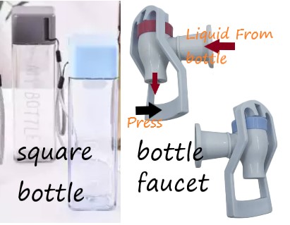
Some of the parts that we update are bottles and faucets. Bottles for drinks that we change at the top into a type of box. Initially we will use direct drink bottles, but the many variations of bottles make it difficult to make bottle holders. So we decided to use a box bottle as a temporary storage for liquid drinks.
From the results of the discussion by considering the ease of placing the sensors, the availability of materials in the local market, the ease of manufacturing and assembling processes, we decided on the first design to be realized.
After the design is approved to be made, the next stage is preparation for manufacturing.
Manufacturing Process
The manufacturing process we will use a CNC router. To prepare an image that will be created by the G Code program, we can use a ready-made design from Fusion 360.
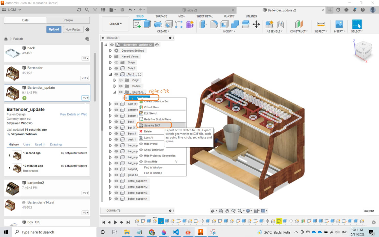
- when we will milling the top shape, then we can export the top sketch component. We expand the tree-menu on the left of Fusion 360 on the component that we will export the 2D shape to. In the sketch section, we select export to DXF, and we name the file.
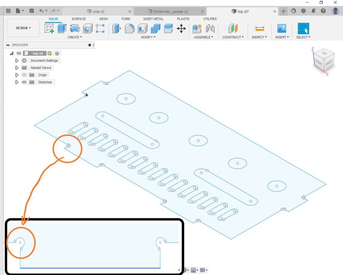
- we open the DXF file earlier as a 2D sketch, make modifications, such as giving a slot according to the router tool diameter for joining. Make sure in the sketch all the lines are connected and there are no double lines. after that we save and we download the DXF file (save it on the local computer).
- do it for other parts that will be routed so that a DXF file is generated to be read in Cut 2D Pro
- Open Cut 2D Pro - Create new file (adjust the size of the material with what you have (I used a size of 1200x2400x15))
- Import vector, select the image (DXF) that was downloaded earlier from Fusion 360. To speed up the process, you can select all images to be processed (as long as the material size is sufficient)
- Adjust the position of the image on the location based on the material shown in the software.
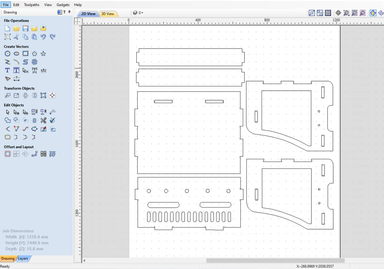
- To check whether the drawing/vector is ready for the toolpath process, it can be viewed with Vector Validator, if it is OK, then it can be continued with the “profile toolpath”.
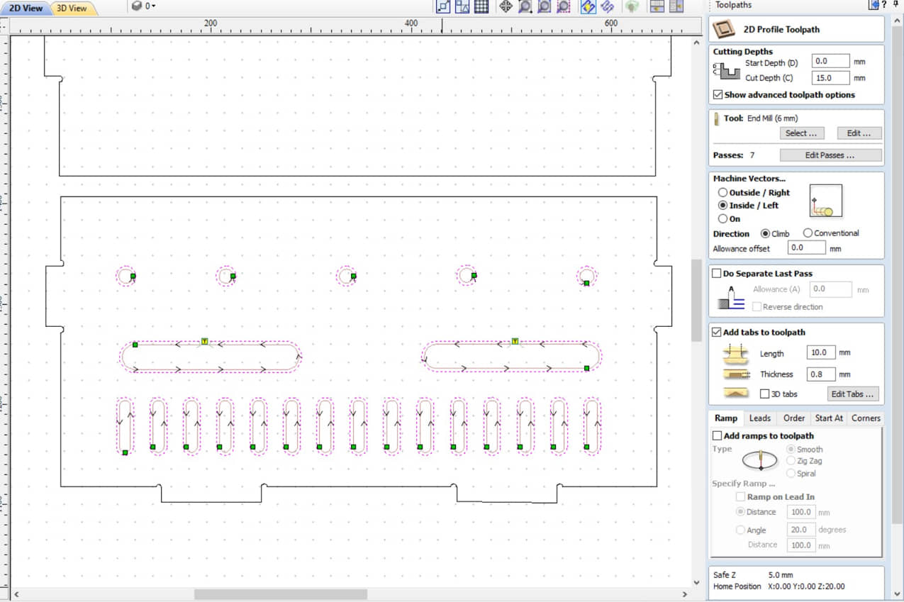
- Select the path to be cut, select the Profile Toolpath menu, depth 15 mm (= thickness); then Calculate
- Do the same for the other path
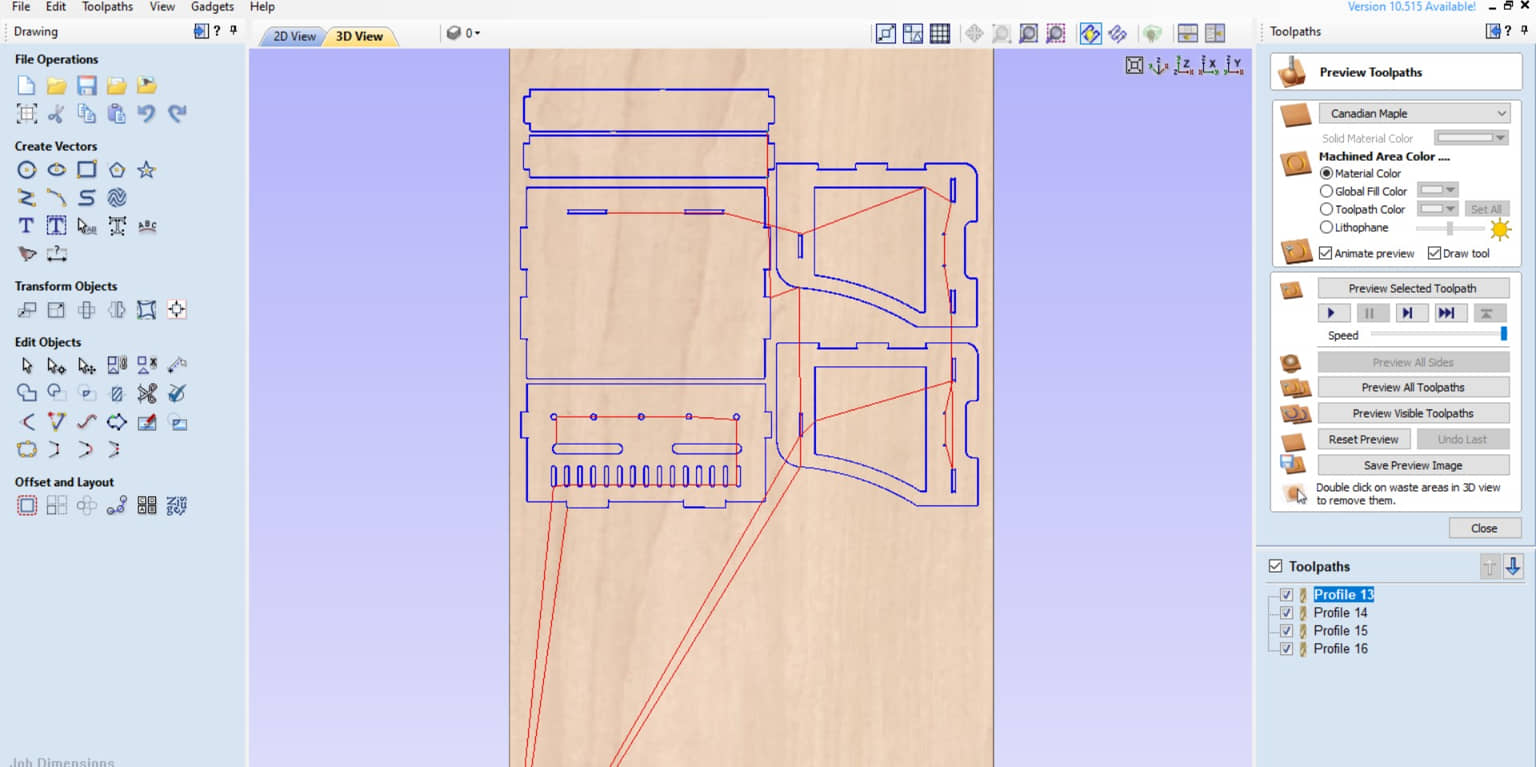
- I preview the toolpath to make sure the cut order, position and shape of the cuts are correct in the provided material.
- After that, I can export the toolpath into G-Code according to the router’s CNC processor. I use General Processor.
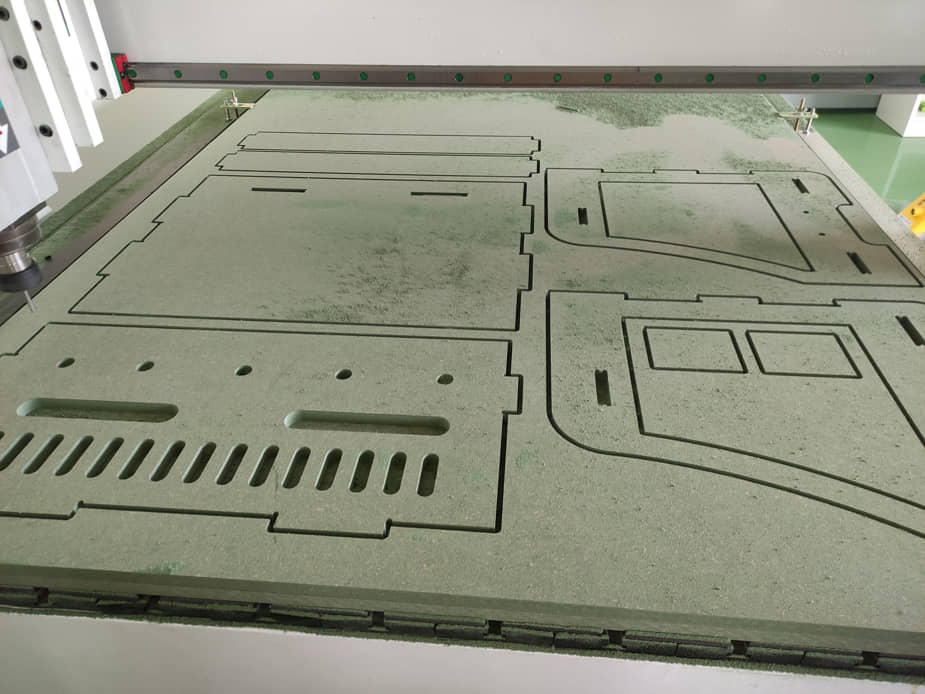
After obtaining the G-Code file, then it is sent to the Handheld controller of the CNC router machine to run.
Info
The setting process, the procedure for running the machine can be seen in assignment week 7
I also designed the table for the glass holder. The table design will have a bend for the cup holder. On the side there is a hole for attaching the belt and the bottom for the bearing on a linear moving system. At the top of the table is also given a place to put a servo motor that functions as a mechanism for opening and closing the bottle tip. This table will be made using a 3D Printer.
Assembling Process
After all the objects are finished, the assembly process is carried out.
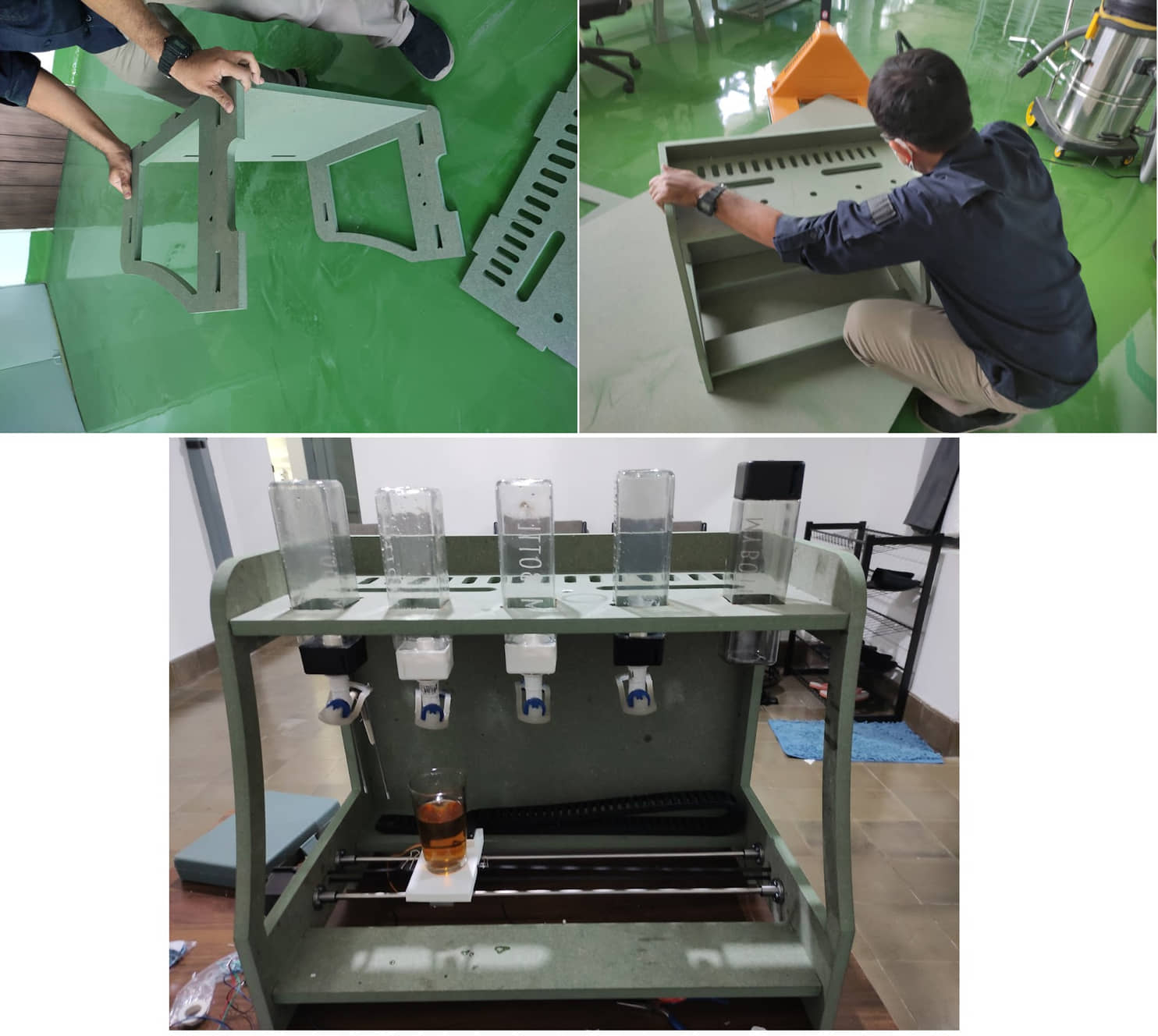
Final Machine
References
Documentation Files
- Top Design (.dxf)
- Wall Side Design (.dxf)
- Wall Back Design (.dxf)
- Wall Bottom Design (.dxf)
- Desk Design (.f3d)
Group assignment learning
- work together to make machines that work automatically
- designing the mechanics system of a machine
- can determine the components system needed to build a machine and also for automation system
- can build and integrate electronics and mechanical systems