3. Computer Controlled Cutting
Week 3 : To do checklist
- Learn about 2D CNC Operations
- Group work
- Lasercutter “Characterization” (focus, power, speed, rate)
- Kerf and joint clearance
- Repo to push group work 2022
- Individual Practice
- Design and cut with vinylcutter
- 2D Parametric Modeling & Toolpath generation
- Starting final Project Process
- Documentations
Assignment (week 3):
Group assignment:
- characterize your lasercutter’s focus, power, speed, rate, kerf, joint clearance and types
Individual assignment:
- cut something on the vinylcutter
- design, lasercut, and document a parametric construction kit, accounting for the laser cutter kerf, which can be assembled in multiple ways, and for extra credit include elements that aren’t flat
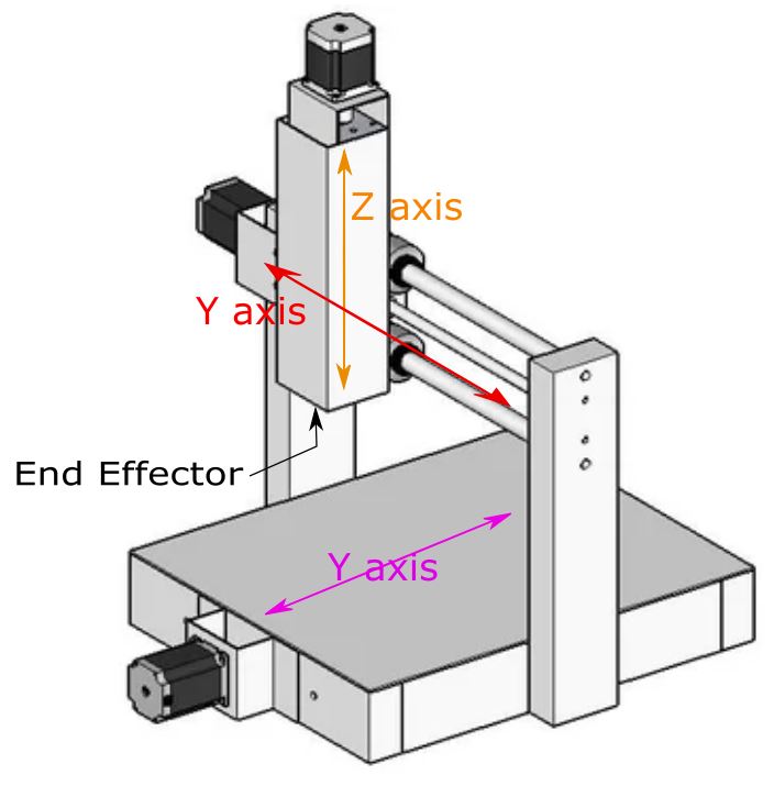
CNC Concept
CNC (Computer Numerical Control) is a machine for the manufacturing process that is equipped with a controller to move the end effector (tools) automatically according to the program being run (G/M Code). This CNC machine concept is now widely used for manufacturing digital machines, such as 3D Printers, 3D scanners, Laser Cutters, Vinyl Cutters, etc. The difference between each of these tools is only in the actuator or end effector used (Nozzle 3d printer, cutter, laser, etc.).
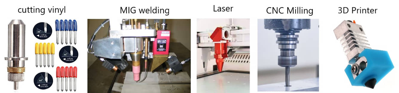
sample of end effector / actuator at various CNC models machines
This week I worked on Computer controller cutting and here the documentation process.
Please click the button for Group Assignment
Group assignment learning
In the group assignment, we studied the characteristics of laser cutting machines :
- Procedure and characteristic for using laser cutting machine (speed, power).
It is necessary to understand so that the laser cutting process can be good and effective. Starting from making the right design, selecting lines and colors for the type of cutting or engraving. Procedures also include machine setup (setting focus, materials) and safety. - There is a “KERF” factor for laser cutting. When the material is cut using a laser cutter, the material on the path will burn so a gap will be occur (KERF laser, around 0.1 - 0.5 mm depending on the material, power, speed). When going to make the material to be paired, this effect needs to be considered so that the material pair can fit.
Vinyl Cutter
Machine settings and cutting
We used the BROTHER SDX1200 Vinyl cutter machine. This machine is very easy and has a lot of features like scan and cutting.
From previous experience, one of the important settings on a vinyl cutter machine is to determine the cut pressure and cut of depth. At the beginning of trying this machine I will see the effect of cutting pressure on the cutting results.
I tried to cut the existing free form provided by the machine, then I varied the pressure settings from -9 to -4. I use this setting to cut 80gr copy paper.
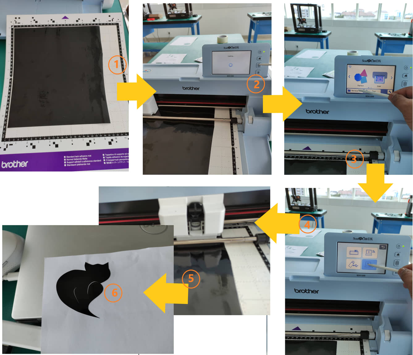
- The first step is a load mat that has been given the paper to be cut
- Load sample pattern, determine the size and place it on the paper position
- Select the cut operation mode, select the cut setting by adjusting the cut pressure variation,
- Do it for several variations of pressure cut.
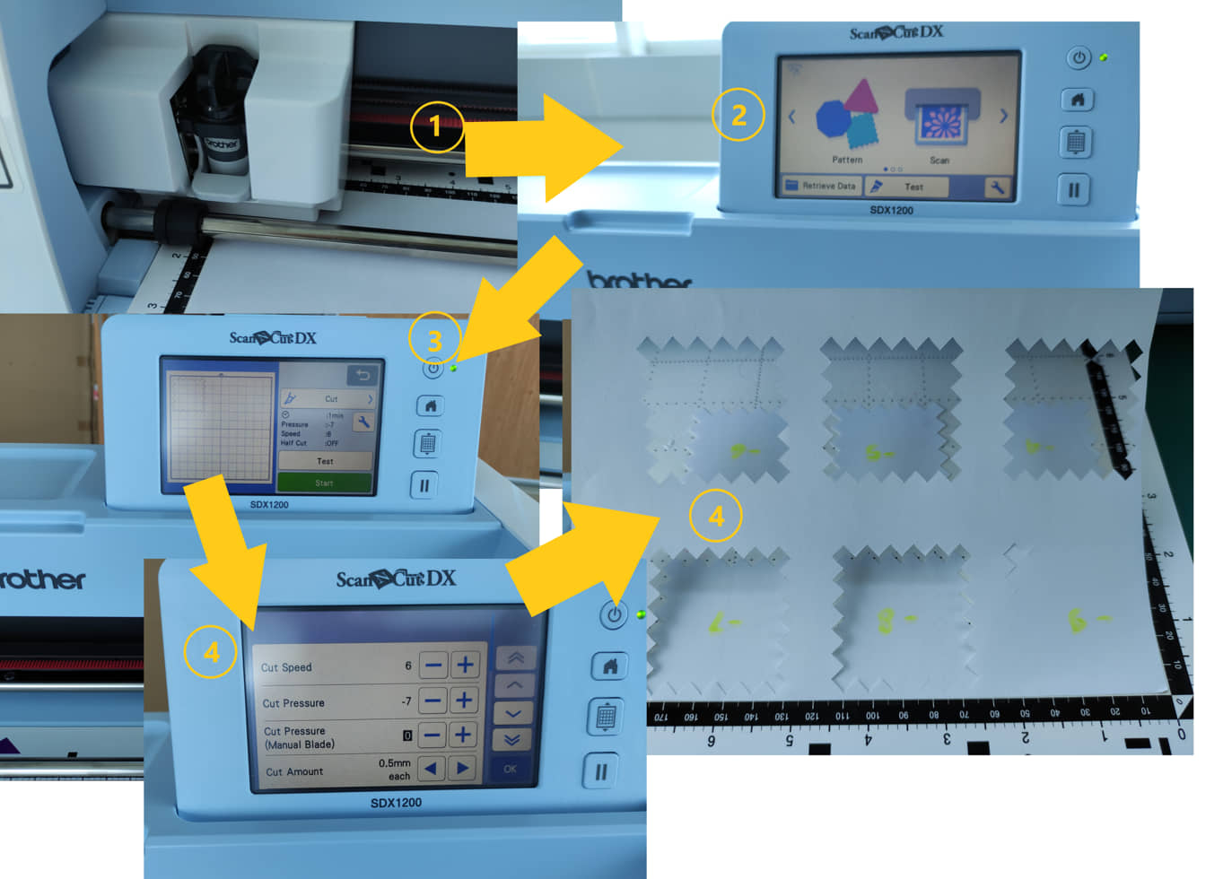
The result shows that the paper can be cut perfectly when the pressure is at least -7.
Design and cut with vinylcutter
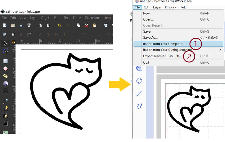
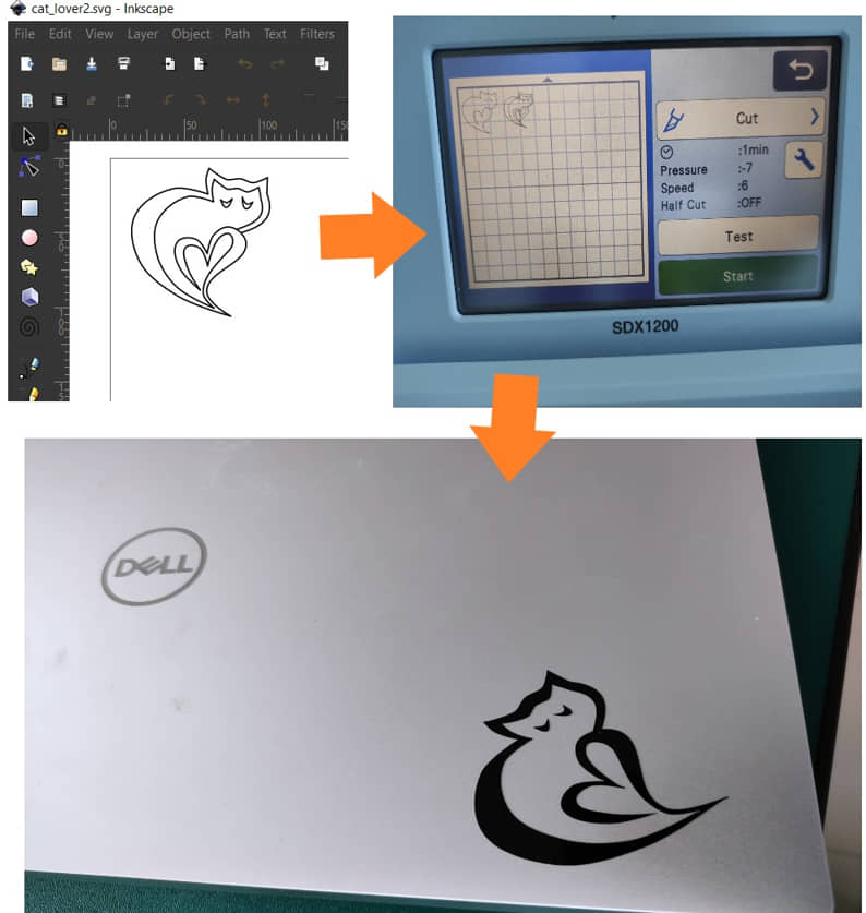
- Design logo using Inkscape, send to vinyl cutter with Brother CanvasWorkspace
- I use the inkcape to draw the “Cat Lover” using Bezier Curve
- save the file (.svg)
- Open the Brother CanvasWorkspace and import the file (.svg)
- Arrange the size, line width, position
- Send to the vinyl cutter machine
Preparation on the machine:
- Paste the vinyl sticker on the mat
- load the mat
- prepare the design, place the image in the cutting position, select “cut”
It turns out that the result of cutting is only on the vector line that is made. cutting results are not satisfactory. Therefore, a design was made by offset on the vector line so that the cut results were better.
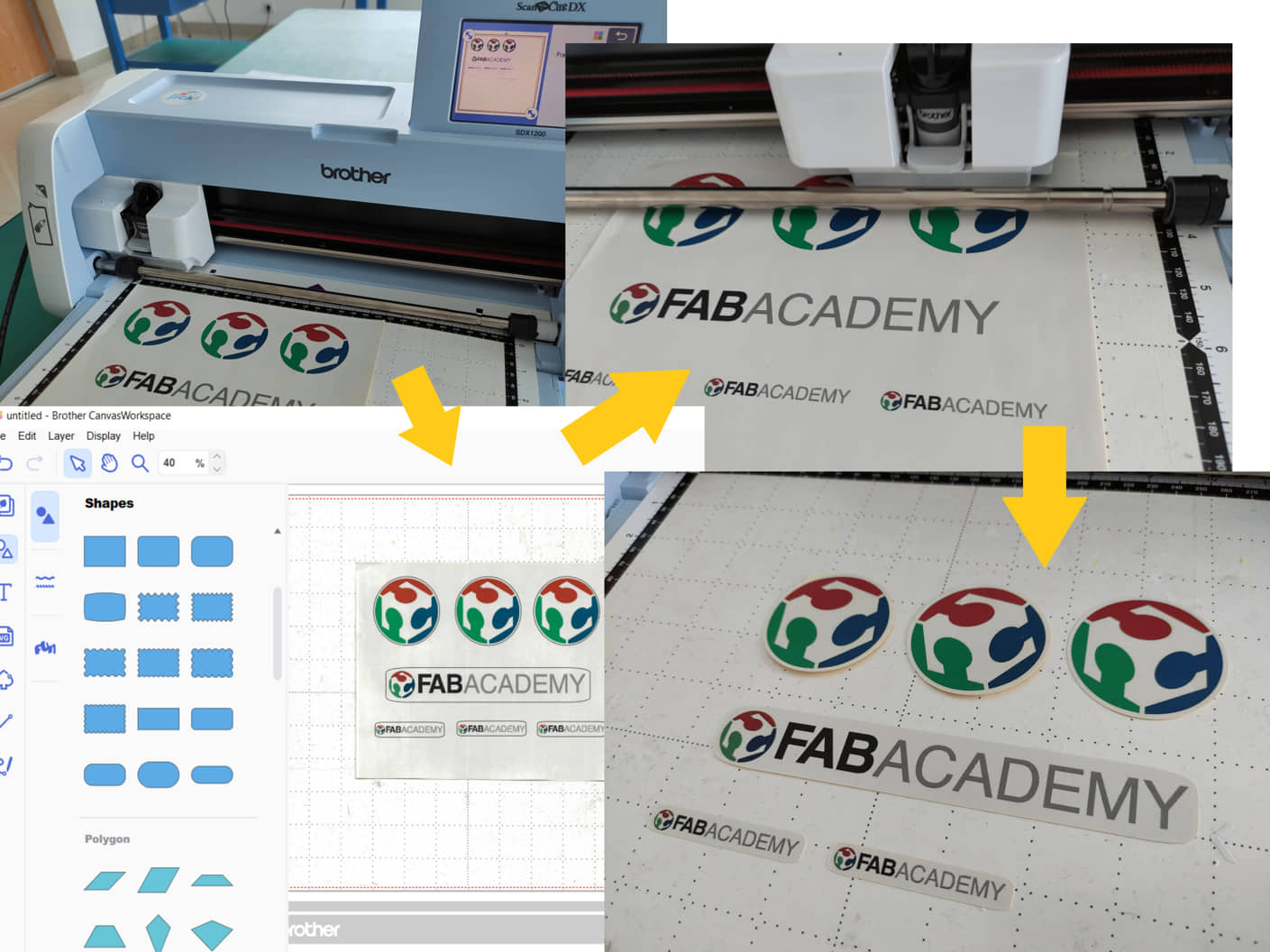
I also did the cutting for the sticker that had been printed on the sticker paper (Print - Scan it and then Cut)
- The first step is to determine the image that will be made a sticker. Designs can be created using Gimp or Inkscape or take pictures from internet sources.
- Logo design printed on vinyl paper
- Perform scanning by a vinyl cutter machine. The results of the scan can be processed on a computer or directly cut directly on the outline object
And this is my Laptop sticker :

2D Parametric Modeling & Toolpath generation
I will make a pair of objects that will take advantage of the gap in the assembly. This design will be cut using laser cutting. The design will also utilize parametric for flexibility in the thickness of the material to be used.
Project I
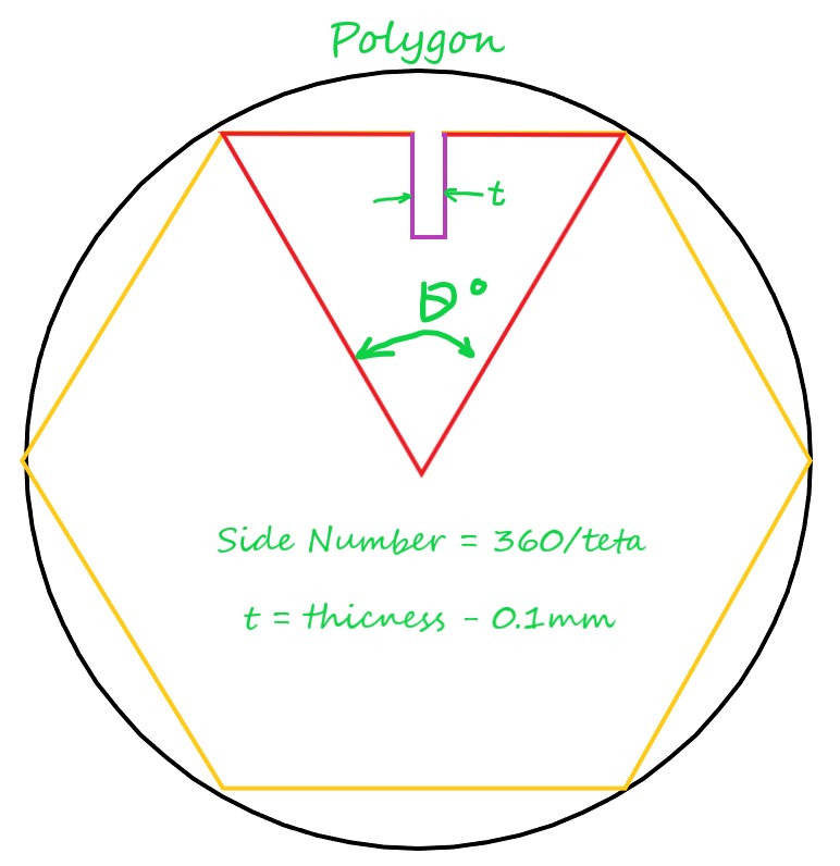
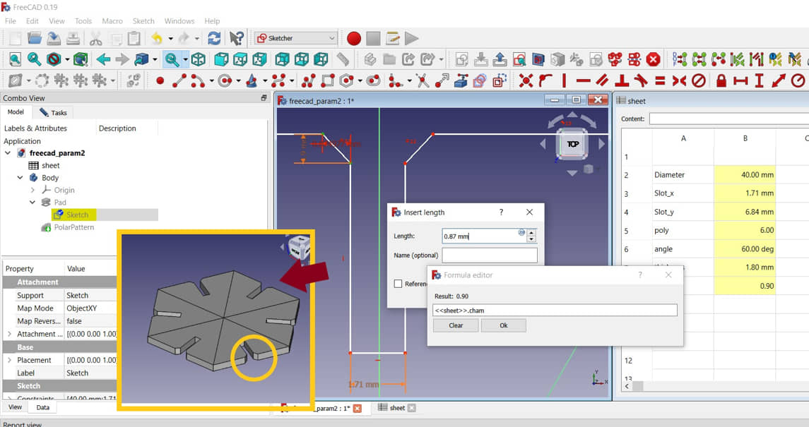
In this task I will create a polygon shape for the shape to press fit then print it using a laser cutter. We created this polygon design using FreeCAD using parametric design. This shape can be customized according to our wishes (number of polygon sides, size / diameter, material thickness), and some dimensions will adjust according to the parameters we enter. As a design basis, it starts from forming a triangular shape as a constituent of polygons. We determine the size of the outer circle and the angles that form the triangle (the number of sides of the polygon is 360 degrees divided by the interior angles of the triangle). From the design using these parameters we can make accordingly materials and shapes without having to draw from scratch.
We start with the design with FreeCAD with free dimension
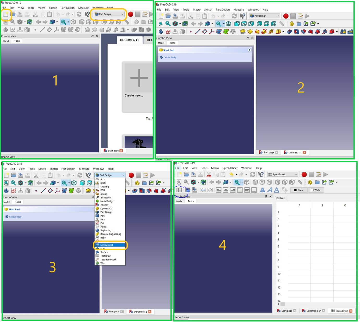
- Open freeCAD, starting with creating a spreadsheet and specifying parameters. To create the spreadsheet we need follow the saveral steps :
- set workbench as part design, create new Document
- Change the workbance to spreedsheat, create new spreadsheet
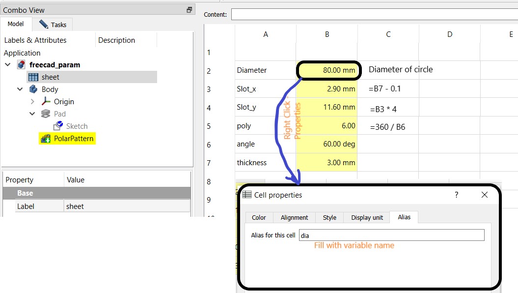
- Setting parameters to be created (Create parameters on the Spreadsheet):
- diameter (outside): 40 mm
- thickness : 3mm
- slot x direction: (thickness-0.1mm)
- slot y direction : thickness * 4
- angle (teta): 60 degree
- side number : 360/angle
Note
We can make the function (like at ms.excel, etc) from cell address (eg. =B2*4)
- Create the Part design (Sketcher) :
- The first step is to make a triangle with sides equal to the radius of the circle.
- Create a symmetric “constraint” between the sides of the triangle
- create a slot to pair between parts (fit-press connection)
- The slot size is the thickness minus the KERF factor (about 0.1 mm for cardboard). The size of the KERF factor can be seen at here
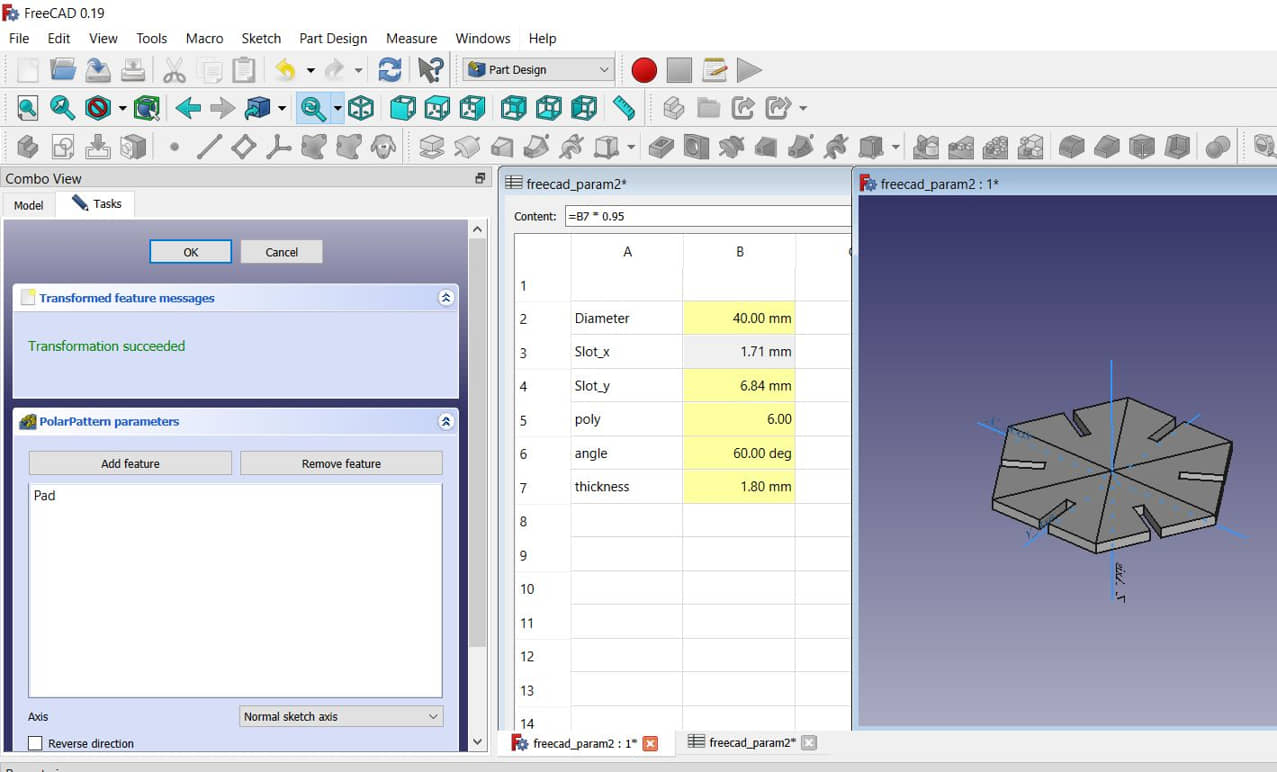
- Enter dimension values using data from a spreadsheet
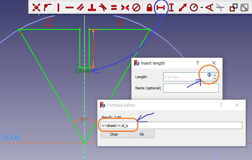
Complete all dimensions with the data in the spreadsheet. if needed add data that has not been entered.
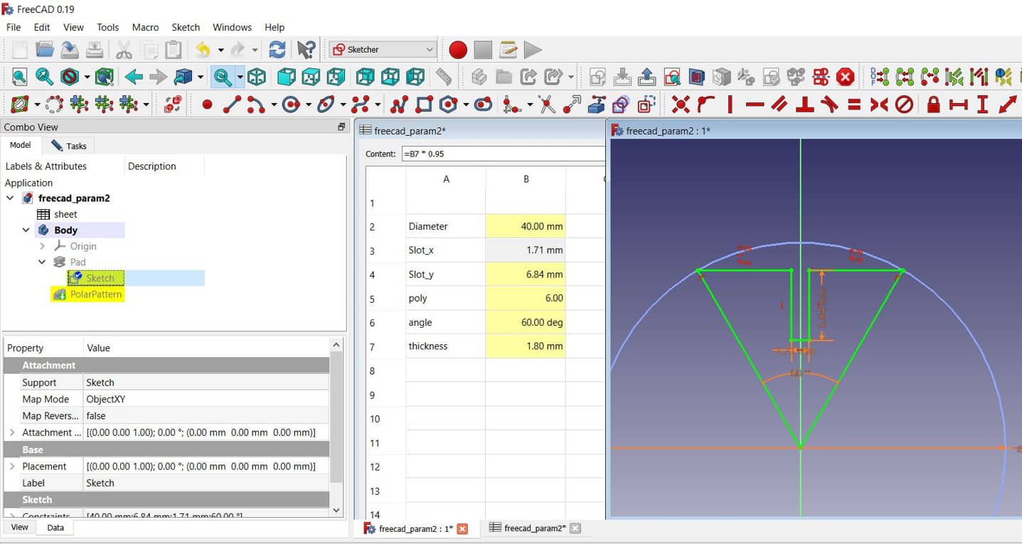
We can change the size of radius or the material thickness (pad) on the parametric (Spreadsheet). For example we use will change the diameter, thickness and angle (number of side). so we can make various shapes as we want by simply changing the values in the spreadsheet.
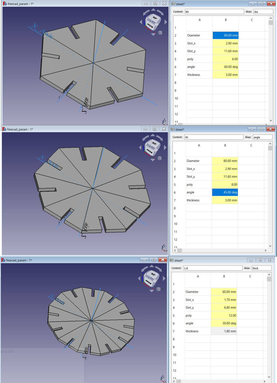
And for this assignment for laser cutting we have “cardboard” with thickness 1.8mm. and we will set the diametrer with 40 mm
- after the design is completed (adapted with the material), we can export the design to the dxf.
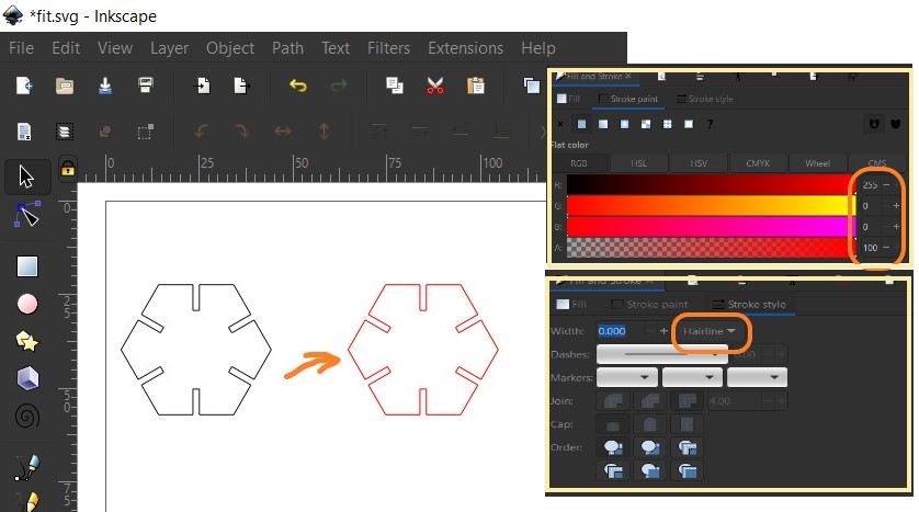
- From the Inkscape program we can import the dxf design graphic
- Seting the color and linetype (hairline) for laser cutting processing
- Duplicate and arrange the object position, setting the type material
- Print it
Laser Cutting Processing
To run laser cutting machine there are several stages: (Details of Laser Cutting Operating Procedure can be seen in Group Assignment)
- prepare printer (from inkscape) settings according to the characteristics of the laser cutting machine,
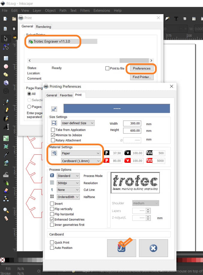
- determine the material template, the type of material affects the power and speed to be set. In the Group Assignment, several examples of the optimal power and speed characteristics used for several materials have been given.
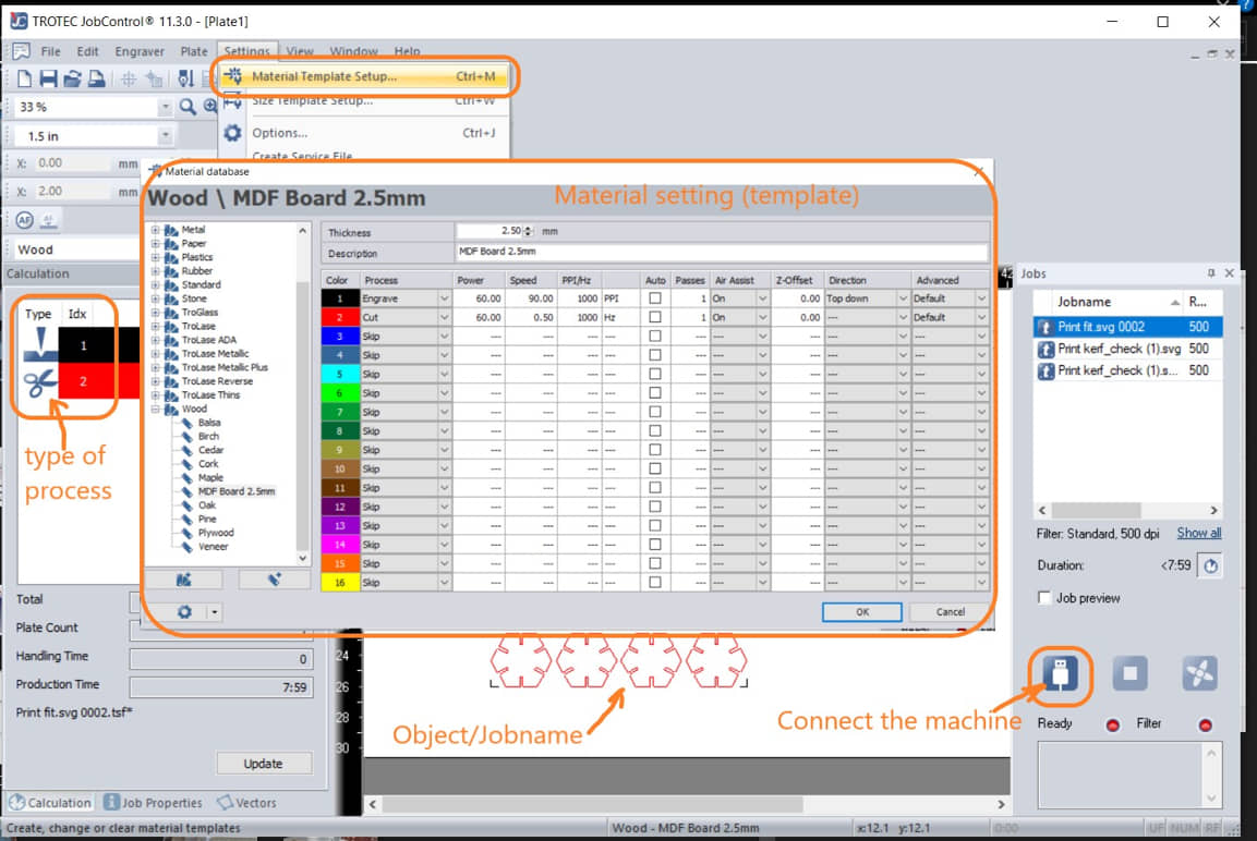
After the print command will appear jobname on the Jobcontrol. we need to prepare the machine first by:
- connect the computer to the machine,
- put materials
- setting focus of laser (Attach the jig to the side of the laser. Slowly raise the table until it hits the jig and falls. This position is the laser focus distance)
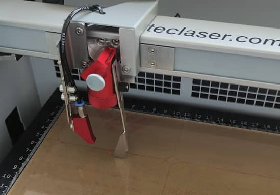
- positioning the laser on the material to be cut,
- if everything is ready it can be RUN to execute the machine
The results : this shape can be paired from several directions and the installation is quite strong because in determining the width of the gap the KERF factor has been considered.
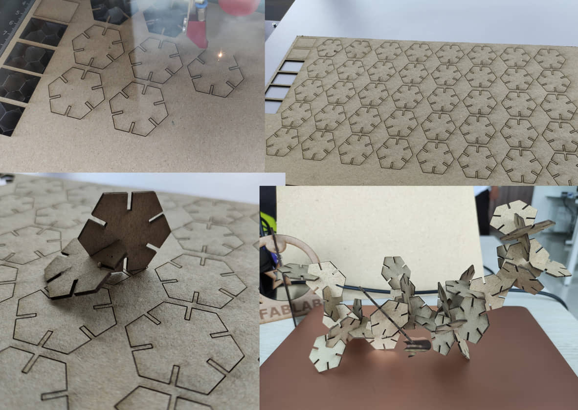
To facilitate installation during assembly, a chamfer is provided at the end of the slot as a guide to assist the fitting process.
- we add chamfer to the sketch
- made parametric chamfer size of 0.5 * thickness
Project II
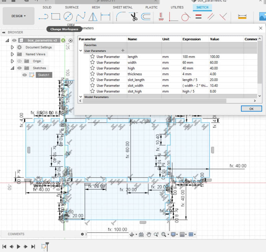
- Desain the object using Fusion 360, make the parametrer for the dimension. Esspesialy for the gap for joining object.
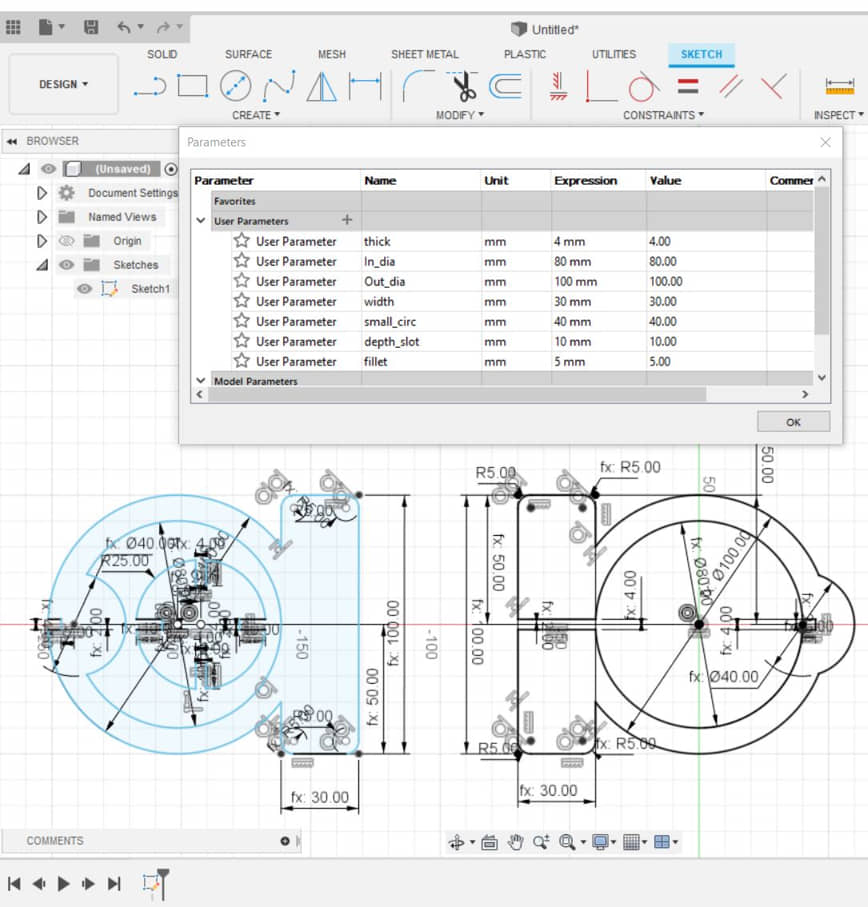
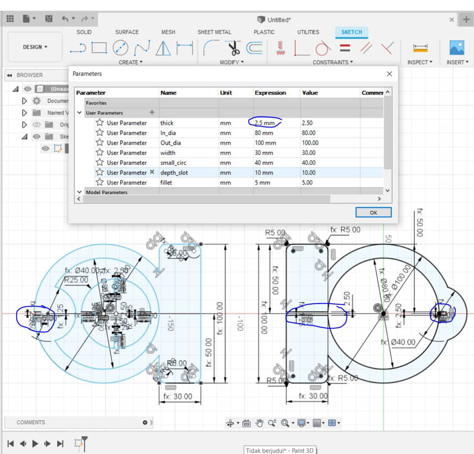
We can change the dimensions on the parametric sheet, the design will update itself, this is useful if in the design of contact between materials and the fitting process. If we want to change the thickness of the board then we don’t need to change the whole design. Automatic use of parameters will update the design. For example, if from the initial design we will change the thickness of the board to 2.5 mm. then the new slot size will change automatically.
- if the design was OK, then we can finish the sketch then export the sketch to dxf file
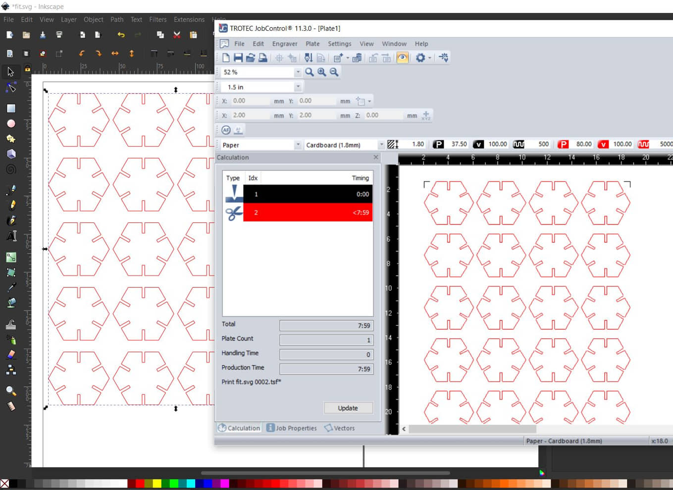
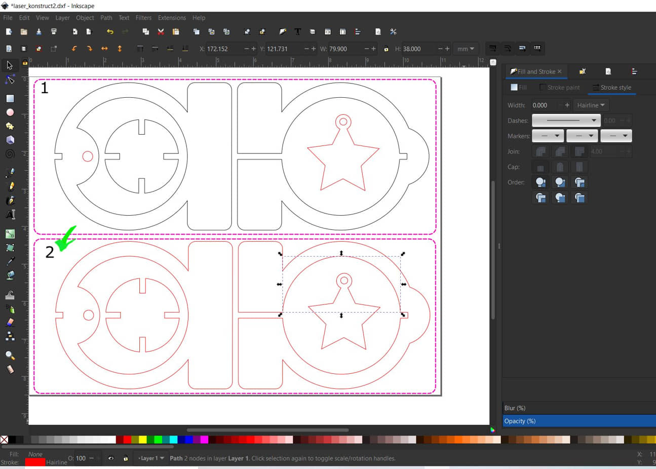
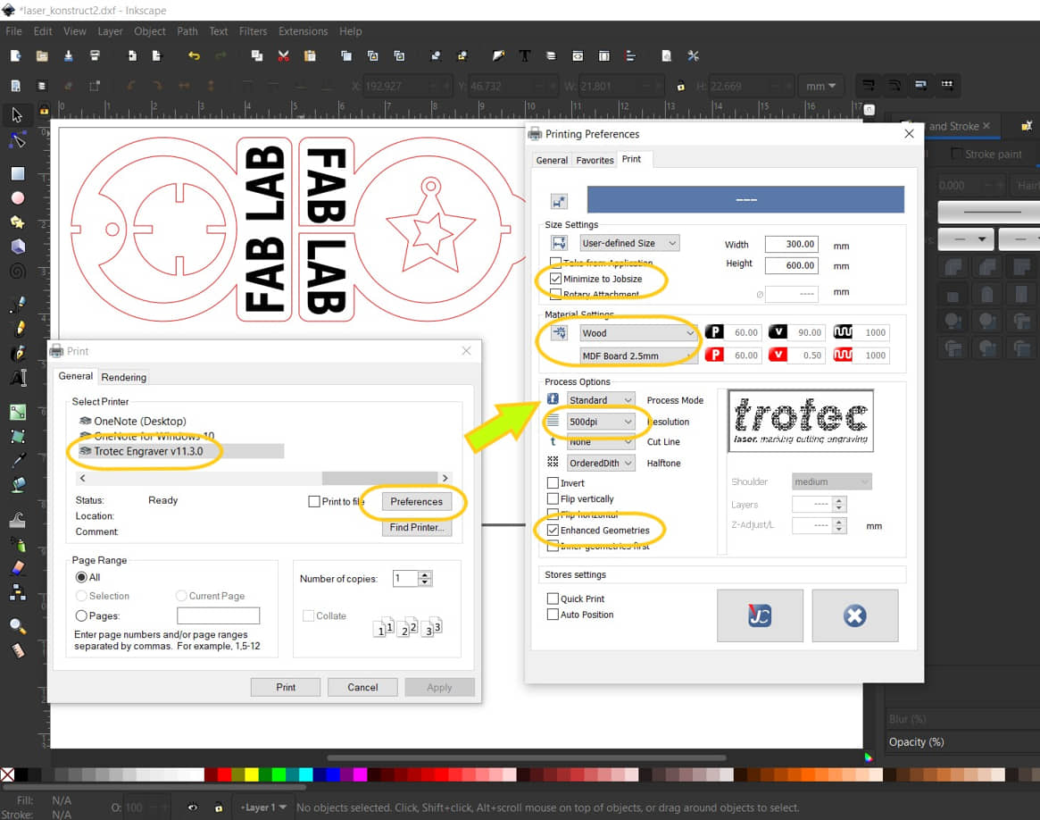
- To prepare the laser cutting proses, we will working with Inkscape - open the Inkscape software
- Import the .dxf file (from Fusion 360), place the object drawing to the page in inkscape
- We need to retouch and modified the drawing :
- Ungroup the object
- Change the colour to the cutting color (red) and the type/style of line to Hairline
- add the another object (if necessary ) and align the position to make efficient process
- Prepare to laser cutting process (Refer to the Group Assignment)
- Setting material cutting
- Prepare materials and machines laser cutting
Project III
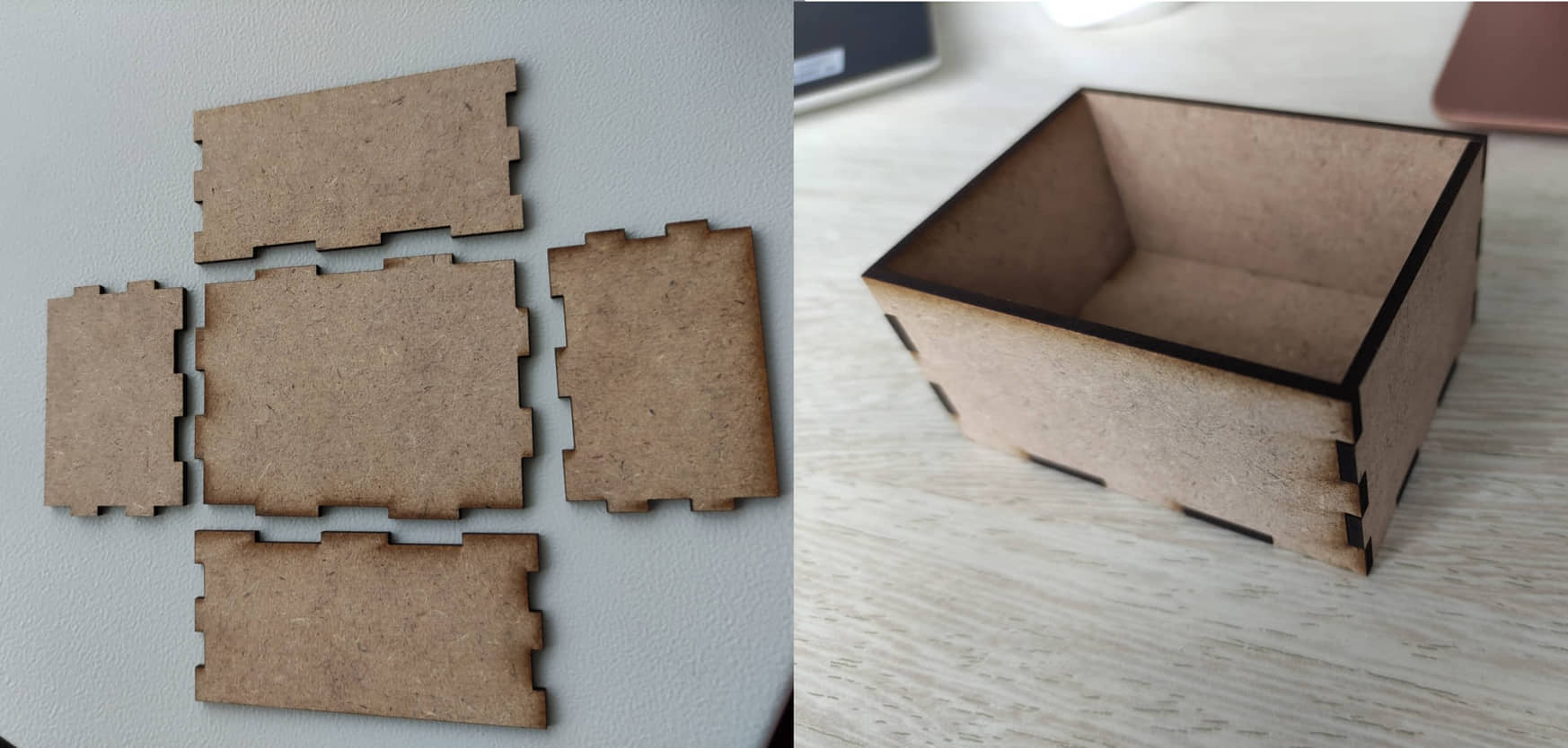
In construction that will be paired, interference slots for fittings will usually be made, known as Press-fit construction. In the design of objects made by laser cutting, press-fit construction is strongly influenced by the thickness of the material. So that each design does not need to be repeated, it is necessary to make a parametric design so that changes in the thickness of the material will adjust automatically. I’m trying to make a box with press-fit construction using parametric on Fusion 360. The existing designs mostly make one side of the box in a separate object. My design tries to economize the movement with one movement as the interface between the sides. This saves on the processing. Also the use of the parametric method can be used to automatically update the design for the thickness and size of the outer box.
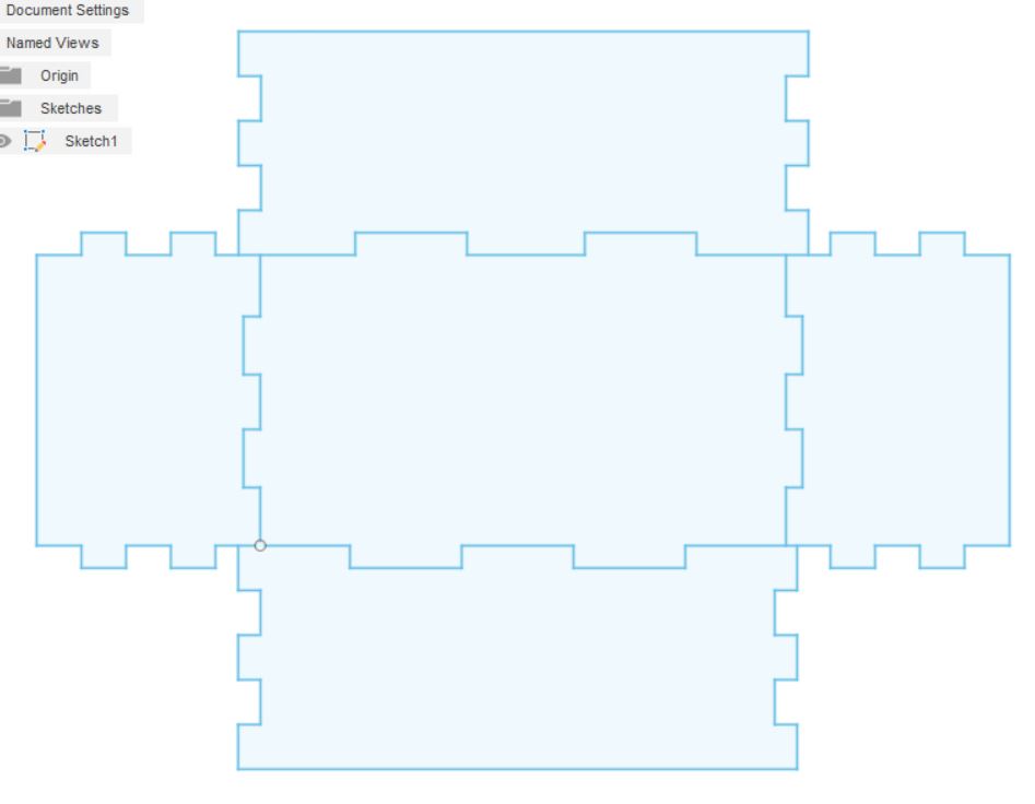
the box design can be access at : Parametric Box for Laser Cutting
- from the design can be export from the Sketch : save as .dxf
- Proses the file with inkscape to proses the laser cutting
- laser cutter kerf effect be minimized by reducing power and maximizing speed by referring to the test results on the Group Assignment
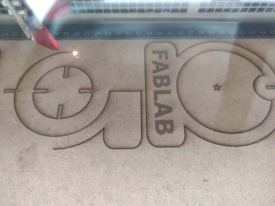
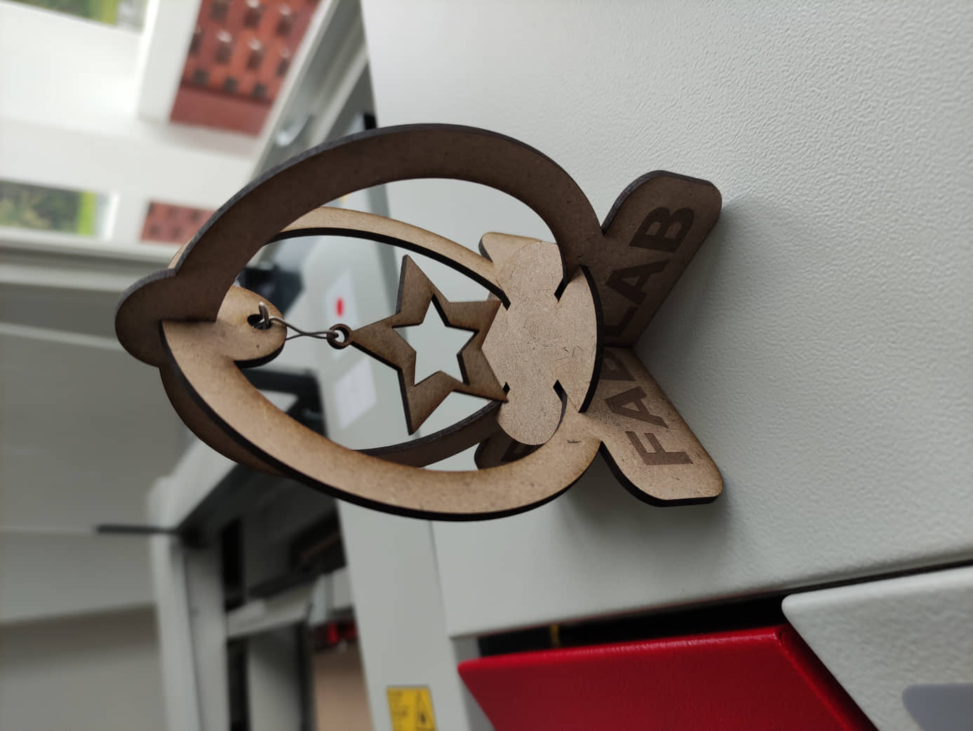
The results :
References
- Kamakura : FA2022/Computer Controlled Cutting
- Kamakura : FA2019 computer-controlled cutting
- Press-Fit Construction Tips
- Parametric SVG
- UNDERSTANDING THE “KERF” OF THE LASER
- Guide To Papercutting - How To Use ScanNCutDX /SDX1200
Documentation Files
- Sticker design (.svg)
- CanvasWorkspace Sticker (.fcm)
- Project I (FreeCAD) (.FCStd)
- Project I (Inkscape) (.svg)
- Project II (Fusion 360) (.f3d)
- Project II (Inkscape) (.svg)
- Project III (Parametric Box for Laser Cutting) (.f3d)
Lessons learned (week 3):
- Understand how CNC machines work
- Understand procedure operational laser cutting machine and the safety
- Can design the shape of objects (assembling) that are processed using a laser cutting machine (parametric, kerf, press-fit)
- Can design and use a vinyl cutter machine