2. Computer Aided Design
Week 2 : To do checklist
- Learn about Raster (Image) and Vector (file type)
- Evaluate and select 2D and 3D software
- 2D Design
- Inkscape : command
- Other CAD 2D Software
- 3D Design
- FreeCAD
- Fusion 360
- Parametric, Assembling
- Renders and Animation
- Design on my Project and Compressing image/video
- Documentations
Assignment (week 2):
Model (raster, vector, 2D, 3D, render, animate, simulate, …) a possible final project
- Compress your images and videos
- and post a description with your design files on your class page
This week I learned about design using both 2D and 3D software. Next I need to update my final project idea and document the process. Before learning about software, we need to understand the concepts of vector and raster.
Warning
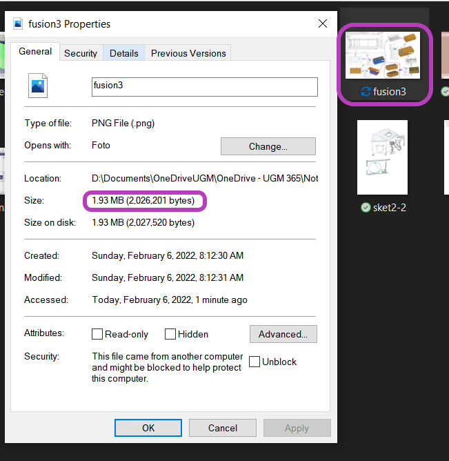
Don’t forget…BEFORE you push your Local Repository to your Cloud Repository…make sure your images have been compressed to less than 200KB each (note KB not MB)..
Raster and Vector
Quote : helpx.adobe.com
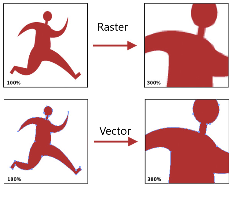
Raster (or bitmap) images are described by an array or map of bits within a rectangular grid of pixels or dots. Vector images are described by lines, shapes, and other graphic image components stored in a format that incorporates geometric formulas for rendering the image elements.
Raster (bitmap) image: At 100% the bitmap, or raster, version of the image looks almost the same as the vector version. Notice that as soon as the raster version is scaled, the pixels on the edge begin to show and the edges no longer look smooth.
Vector image: The vector image is created by defining points and curves. (This vector image was created using Adobe Illustrator.) When vector graphics are scaled, the edges remain crisp and sharp no matter the size.
 We tried to compare images and vectors using inkscape
(copy some image and write/draw object then compare it)
We tried to compare images and vectors using inkscape
(copy some image and write/draw object then compare it)
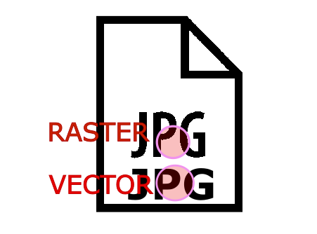
and then zoom in :
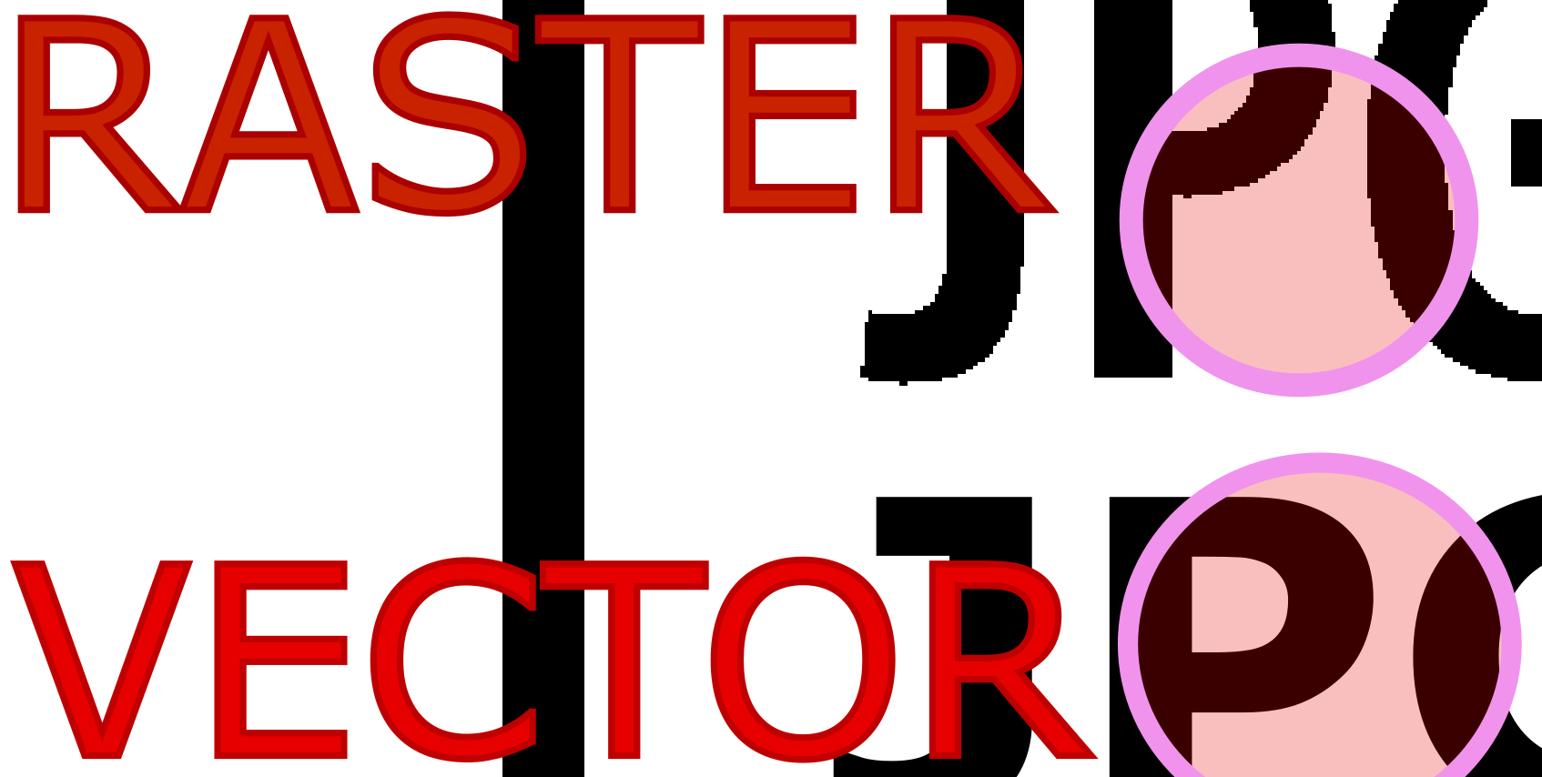
It can be seen that the raster/image when zoomed in to a certain magnification will look not smooth because it is based on pixels, while in the vector image when zoomed the image remains in a smooth state.
2D Design
2D Design is a drawing of objects that have two dimensions such as length and width. 2-Dimensional Graphics is a drawing technique that is generally based on the coordinates of the x and y axes (flat). There are many 2D software, both raster and vector based.
- Raster-based software include: GIMP, BIMP, Photoshop, Pixlr, MyPaint, Krita, Geeqie, ImageMagick.
- While vector-based ones such as: Inkscape, lodraw, Illustrator, Sketchpad, CorelDRAW, Scribus, QCAD, FreeCAD.
I will try to use and explore one of the 2D Design software for drawing
Inkscape
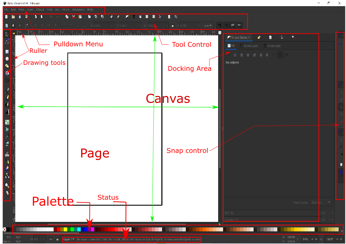
Inkscape is a 2D Design software, free, open-source, cross-platform (Windows, Linux, Mac), 2D, vector graphics software (similar to Adobe Illustrator). When inkscape is opened, you will see an image area (canvas) and several menus and toolbars.
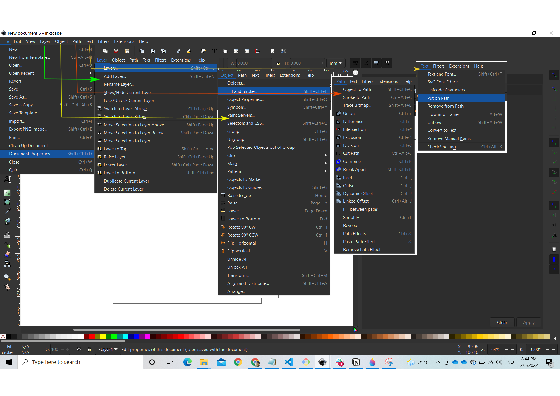
Some important things to know about inkscape operation:
- Setting page (Document Properties)
- Export and Import file
- Layer
- Drawing (Lines, Shape, Object)
- Object Menu:
- Fill & Stroke
- Group & Ungroup
- Raise/Lower
- Path Menu :
- Boolean Operations,
- Object to Path,
- Stroke to Path
Drawing practice (for my project)
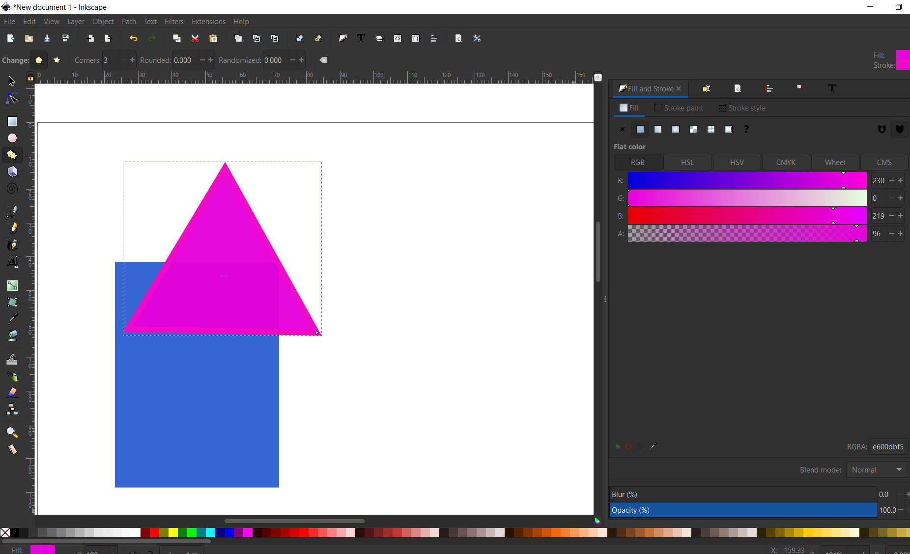
- File - New (drawing) -> Draw rectangle and polygon (triangle) -> fill and stroke
- Import image (cat) -> create circle, place the image and reposisioning the shape
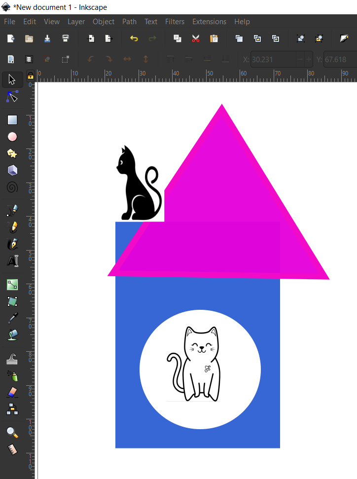
- Draw bezier near the circle -> edit paths by node -> select every node with auto-smooth
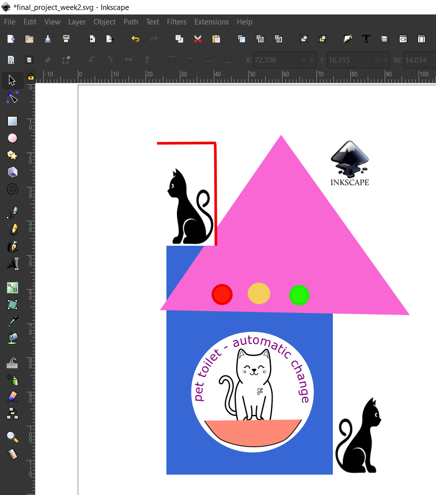
- create text “pet toilet - automatic change” -> select the text and path -> put on path (text)

- rearrange and retouch some image shapes
Warning
Don’t forget…to save your project (Ctrl+s)
Reference :
Other software 2D Design
We also try to learn with other software like : photoshop, gimp, paint, coreldraw, etc. Not very deep but it has provided interesting things for me to know some of these software.
GIMP
free and open-source raster graphics editor used for image manipulation (retouching) and image editing, free-form drawing, transcoding between different image file formats, and more specialized tasks. It is not designed to be used for drawing (Wikipedia).
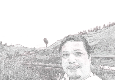
I’m trying to edit my profile picture into a pencil sketch using Gimp.
- open the image using Gimp
- duplicate the layer with (Ctrl - Shift- D) twice
- at the top layer : change the mode to the Dodge
- Invert color
- Apply value Propagate Filter do it 2-3 times
- Merge the layer
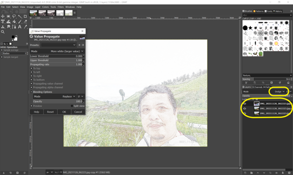
source image :

results image :
3D Design
FreeCAD
FreeCAD is made primarily to design objects for the real world. Everything you do in FreeCAD uses real-world units, be it microns, kilometers, inches or feet, or even any combination of units. FreeCAD offers tools to produce, export and edit solid, full-precision models, export them for 3D printing or CNC machining, create 2D drawings and views of your models, perform analyses such as Finite Element Analyses, or export model data such as quantities or bills of materials.
Drawing practice
I will try to use FreeCAD to get experience making 3D Model objects.
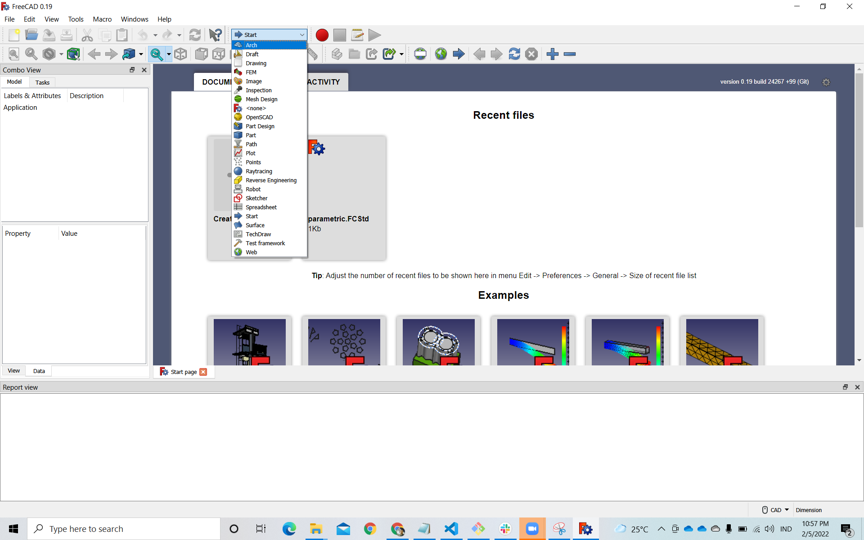
It is very important to determine the type of workbench when working with FreeCAD
- Create the new Document -> save the name
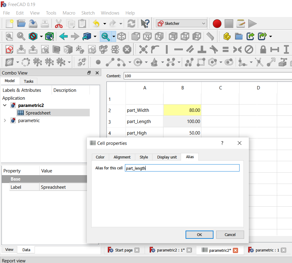
- Start with parameter : start with spreadsheet workbench -> create new spreedsheet : fill each parameter and value, create the alias of the value (by right-click the value)
Info
Parametric design is a process based on algorithmic thinking that enables the expression of parameters and rules that, together, define, encode and clarify the relationship between design intent and design response
- Create the new sketch (schether worbench) -> xy plane orientation
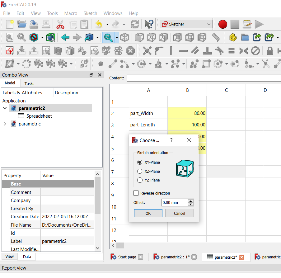
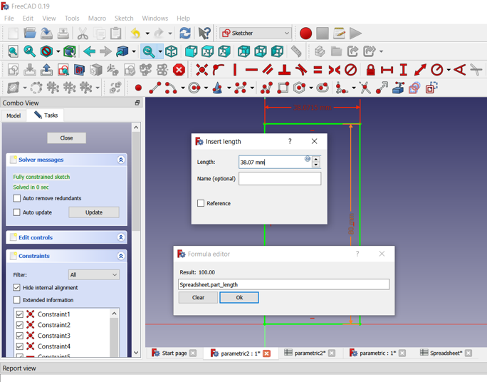
- create the rectangle and give the dimension (vertical and horizopntal) with parameter dimension (spreedsheet) according to the determination of the dimensions on the parameters.
Spreadsheet.part_width
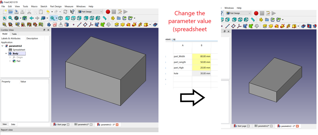
 we will get a sketch drawing with a size according to the parameters. If we change the parameter value then the size of the sketch also changes.
If we want to create a 3-dimensional part, then we can use the “part” workbench. then the sketch that we have created can be directly extruded with the desired height.
another way
There is another way to make 3D parts so that each part can be identified in the body part.
- After creating a spreadsheet, the workbench is actived into a part design.
- Make a sketch by specifying the base plane (xy plane)
- Create the sketch (exp : rectangle), enter the dimension value with the spreadsheed parameter -> finish
- Make the 3D design with pad, enter the extrusion value with the high parameter value
- We also can create dimension with parameter wit expression
Spreadsheet.part_width / 2
Info
There are still many other menus that must be studied to be able to produce 3D drawing models.
Reference :
Fusion 360
Fusion 360 is a cloud-based 3D modeling, CAD, CAM, CAE, and PCB software platform for product design and manufacturing.
- Design and engineer products to ensure aesthetics, form, fit, and function.
- Reduce the impact of design, engineering, and PCB changes and ensure manufacturability with simulation and generative design tools.
- Directly edit existing features or model fixtures with the only truly integrated CAD + CAM software tool.
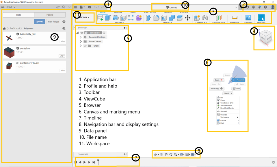
Introduction
When using Fusion 360 we must begin to recognize the appearance of the interface. Fusion 360 is a cloud application-based 3D modeling design software. When we first log in we are asked to enter an account. For students or educators, we can register for an education license.
To start drawing with Fusion, we have to set the location where the file is saved by selecting/creating a folder in the Data section of the panel
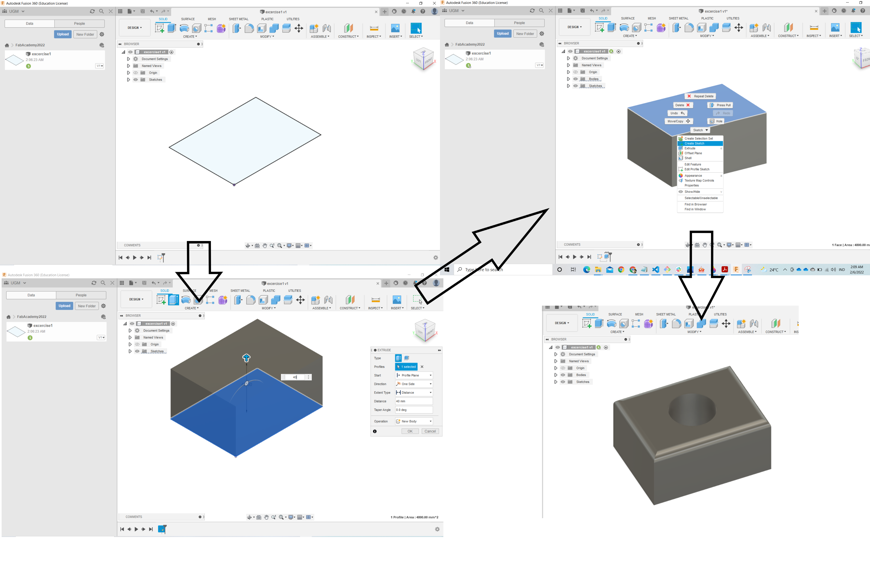
- Draw a sketch by selecting a plane or planar face.
- choose a sketch shape (eg: rectangle), dimensions can be entered (change dimensions by pressing the “Tab” button
- After finishing the sketch, press finish sketch
- To make a 3D model, we extrude our sketch, enter the required height value
- We can also make holes. By making a sketch on the surface of the object (pick the surface then -right click- select new sketch)
- Create profile sketch that will be used to make holes (eg : circle)
- Extrude the sketch towards the object (choose cut) then the main object will be perforated
- We can also do other modifications such as chamfer, fillet, shell, split.
Parametric CAD Modeling Workflow
Very similar in any Parametric CAD software (include Fusion 360)…only the names and location of tools differ in the software’s interface.
- Create a SPREADSHEET of parametric dimensions. 3D modeling is a key process for getting your ideas from a concept to a reading state for creation, making it the core foundation of the product development process.
- 2D SKETCH on a drawing plane. Many features that you create in Fusion 360 start with a 2D sketch. In sketching complex objects, certain strategies are needed so that the results can be obtained accurately and quickly.
Note
- In Fusion 360 it is important to “snap” entities to the origin when possible. This accurately grounds the objects and ensures they will behave as expected.
- We must “stop” a sketch before you can continue building geometry since Sketch is a mode that you enter and exit within workspaces.
- One sketch may contain multiple profiles. In this case there is a profile inside the circle you drew and a profile between the outer edge and the inner circle. You can select multiple profiles for an extrude feature. In this case you will only select the outer profile.
- DIMENSION & CONSTRAIN the drawn Sketch lines
Note
Constraints create relationships in your sketch. By saying that these two points are “vertical” determines how the will be aligned in the sketch. These relationships are persistent, meaning that if the center of the face moves, the sketch will move also.
- EXTRUDE/REVOLVE the 2D Sketch into a 3D object (often called a Body) with feature operation
- MANIPULATE, COMBINE, TRANSFORM bodies…into the final object
- The final object can then be RENDERED & ANIMATED…to aid visualization
- If required drawings must be made in working DRAWING to documentation and transfer of information to other sections
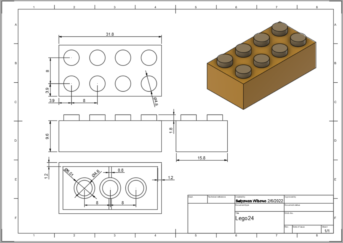
Drawing practice
Make sketch and model 3D
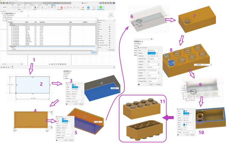
- Starting with make the parametric data : “click Modify menu - Change Parameter”
- Fill the parameter and the value
- Create the Component (Brick) : Create the sketch, fill the dimension with the parameter
- Create the Component 2 (Nubs) : Array the component to the x (4 pcs) and y (2 pcs) direction
- Create the Component 2 for lower (NubsBT) : Array the component to the x (2 pcs) direction
Rendering
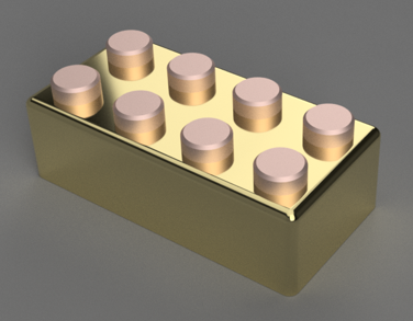
We can change the appearance of the part to make it attractive and look like a real object with the rendering process. The rendering process is carried out using the Rendering Workspace. Select Rendering and then select the color or material for each component. Rendering can be done on a cloud system or if our computer is capable enough to render it can be done in our computer. We can setup the the material; appearance, scene of the part before we render.
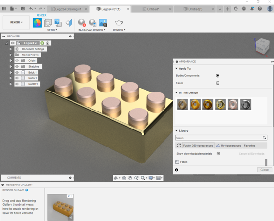
the result :
Drawing
The working drawing can be develop with DRAWING Workspace.
- We can create the drawing from the design or from the animation
- We can set the configuration (projection style, paper size, border, etc.)
- Place the base view on the page as front view (Usually the most informed view is put as the front view)
- Place the Projected view based on the based view. Determine the number of views as needed (top view, right/left view, section, etc.)
- We can change the parameter value, and then the dimension of the part will be change according to the new size entered
Assembling
If we used two or more parts that we created and then we need to assembling, we will used Assemble Menu
Animations
File support documentations
The link of Fusion file (.f3d) can be access at : lego fusion or download at Fusion 360 File
The drawing can be download at Drawing file
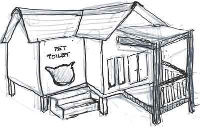
Design my Final Project
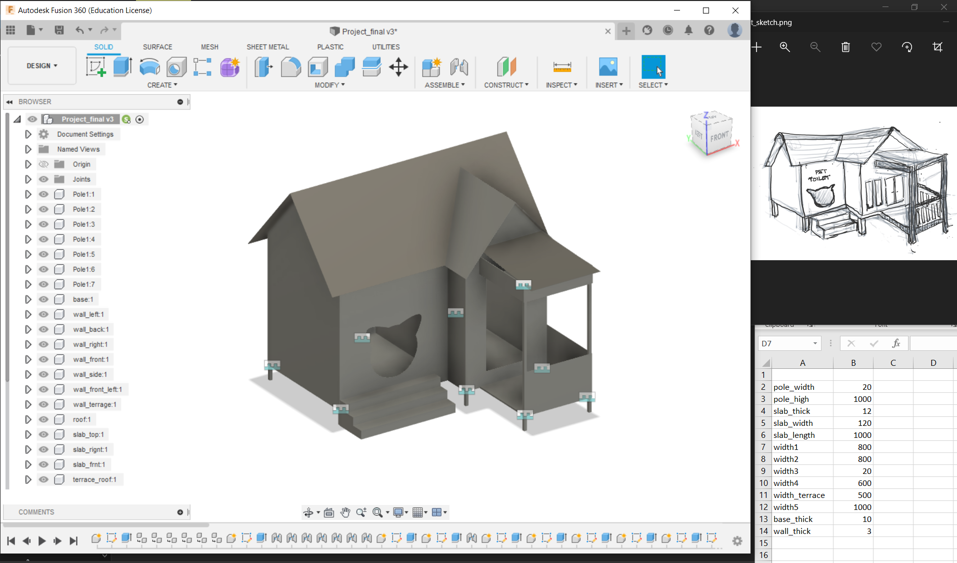
There was input from the instructor in the final project (Smart Cat House), that the house could be designed using traditional houses in Indonesia. I think this is a very amazing suggestion, and the house was modified like a traditional Sunda House. The sketch after updating the sketch design becomes the following
To create the design model with Fusion 360 take the following steps:
- Create the new file on the project directory and save the file
-
Make the parameter value from “modify -> change parameter”
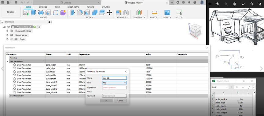
-
Create the component for each part in design, it will be construct or assembling to be one device
-
Create the sketch and enter the dimension withe the parameter, after finis the sketch “finish sketch” then extrude
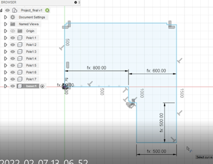
-
After we get several part/component, we can assembling into one device. Select plan and snap position for each part that will be construct, Apply and then the part will be join. Do it for each component that was created
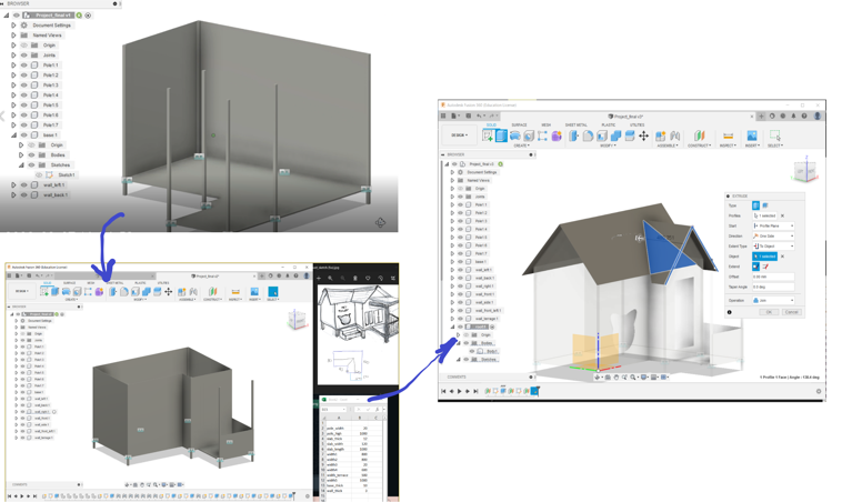
this is the results:
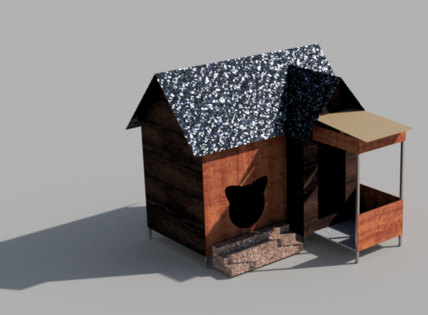
To make the image more attractive, we can render it. We can adjust the material, background, lighting, color, etc. The results are as follows:
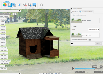
The render can be add with the environment as the background. A environment template from Fusion 360 has been provided, but we can add our own environment using an image of type .hdr. The source of the image can be obtained one of them from the following link: Source. After download the image, we have to convert it to hdr file.
Info
The design still the house, the mechanism and electronic devices not shown yet. It will be completed in the next lesson.
The Fusion 360 Project file can be found it in : Project fusion 360
or can be download at Final Project 3D Design
Reference :
Editing nad Compressing Images/Video
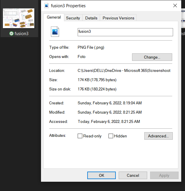
For documentation purposes on the website, management of the file system and file size is very important. Especially on images and videos that will be used for web materials. If the size is too large then the space becomes full quickly and the website loading takes a long time. So we need compression techniques for website material such as images and videos.
Images
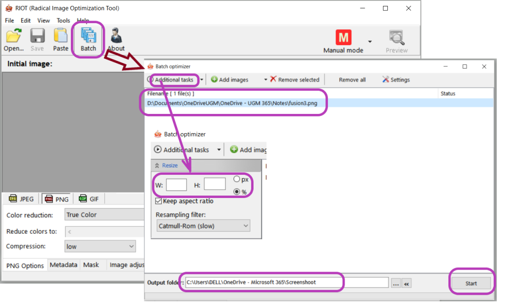
There are lots of software to resize images, such as: Image Magic, XnConvert, Riot and others
for example using Riot
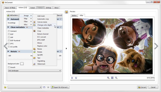
XnConvert
Video
Several software for Video editing and recording :
-
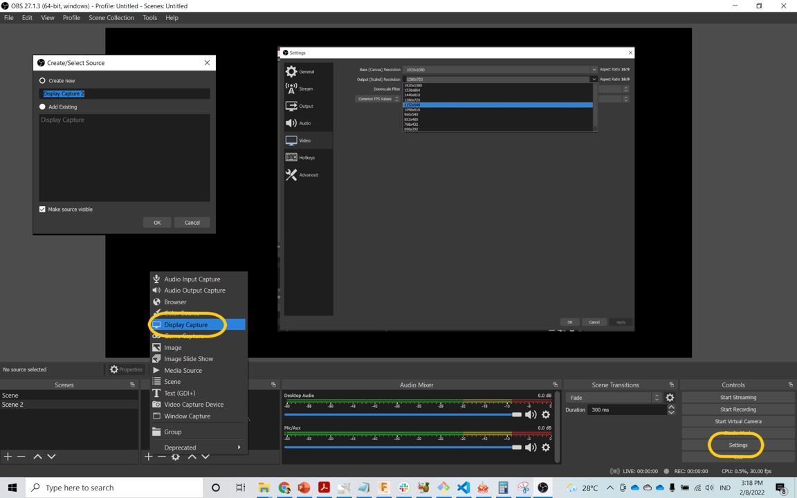
OBS Studio
Free and open source software for video recording and live streaming. I try to record my screen laptop with OBS Studio. We can add the source with : Display Capture. To manage and setup the video configuration, select the setting menu and choose the Video configuration. set the HotKeys to start/pause/stop the recording.
-
ffmpeg
the software that powerful video compression, command line interface. ffmpeg is a very powerful text-based tool for processing videos such as compressing or converting videos. There are several commands that are commonly used:
- Command-line - Compress and Convert MP4 to Webm for YouTube, Ins, Facebook
ffmpeg -i source.mp4 -c:v libvpx-vp9 -b:v 0.33M -c:a libopus -b:a 96k \-filter:v scale=960x540 target.webm- Command-line - Compress and Convert H.264 to H.265 for Higher Compression
ffmpeg -i input.mp4 -crf 30 output.mp4// "input.mp4" is source video // "output.mp4" is target video // 28 is compression ratio- Command-line -Set CRF in FFmpeg to Reduce Video File Size
ffmpeg -i input.mp4 -vcodec libx264 -crf 24 output.mp4- Command-line - resize video in FFmpeg to reduce video size
ffmpeg -i input.avi -vf scale=852×480 output.avi
-
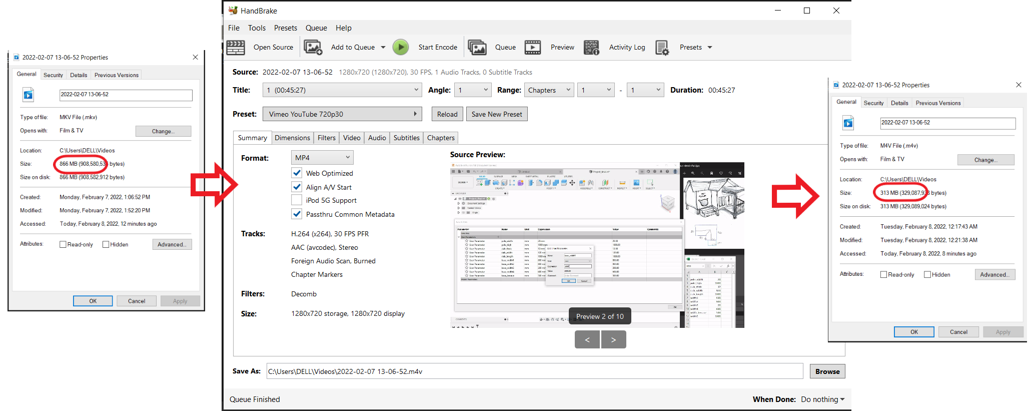
Handbrake
The IDE version of ffmpeg. 233 / 5.000 To install Handbrake we must first install the code .NET 6.0 Desktop Runtime (v6.0.1) - Windows x64 Installer!
When we have videos to upload to the web. we have to compress the file size so that the website can be displayed smoothly and does not meet the storage limit. I try to use the Handbrake (the IDE software for video compression). I have video from my documentation of screen recording when I operated the Fusion 360. I’m trying to use Handbrake (IDE software for video compression). I have a video from my screen recording documentation when I ran the Fusion 360, but the file size is big enough (866 MB) that it needs to be compressed. when compressed the file size is made for web support. The final result is a file size of 313 MB.
Documentation Files
- Inscape Exercise .svg
- FreeCAD Exercise .FCStd
- Fusion 360 Exercise .f3d
- Fusion Drawing .pdf
- Fusion 360 Final Project 3D Design .f3d
Lessons learned (week 2):
- Able to use 2D design software such as inkscape and use it to create project drawings
- Designing the final project with 3D CAD design (Fusion 360)
- Using and selecting several CAD software (Inkscape, FreeCAD, Fusion 360)
- Compressing image/video