8. Embedded programming
Week 8 : To do checklist
- Learn and Practice read the datasheet of Microcontroller (ATtiny 3128)
- Group work
- check the avalibilty of MCU (different architecture)
- Test and running the MCU
- Repo to push group work 2022
- Individual Practice
- programming MCU (ATtiny 3128 with IDE, AVR and Python communication)
- compare the results
- Continue the final Project Process
- Documentations
Assignment (week 8):
Group assignment:
- compare the performance and development workflows for other architectures
Individual assignment:
- read the data sheet for your microcontroller
- use your programmer to program your board to do something
- extra credit: try other programming languages and development environments
This week I worked on Embedded programming
Please click the button for Group Assignment
Group assignment learning
- In the group assignment, we studied the saveral type of MCU
- What is the difference of MCU
- How and why we choose the MCU
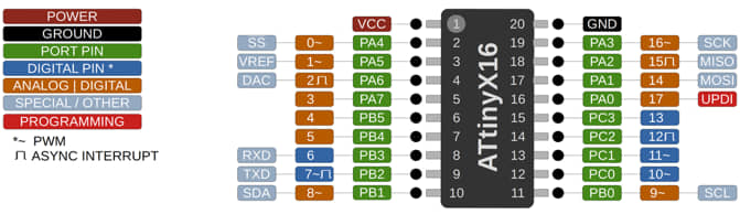
Read datasheet ATtiny-3216
Datasheet is an information sheet made by an electronic component manufacturer that contains information about the electronic components it makes. The datasheet will provide all information about the component, from the shape, characteristics, properties and everything related to the component so that the use of the tool can be correct and optimal.
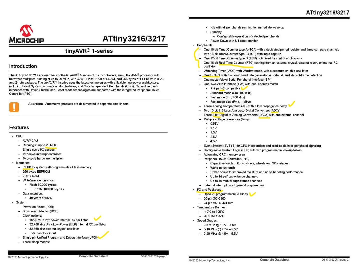
The ATtiny3216 series of microcontroller features the 8-bit AVR® processor with hardware multiplier, running at up to 20 MHz and with up to 32 KB Flash, 2 KB SRAM and 256B of EEPROM in 20-pin packages. The series uses the latest Core Independent Peripherals with low-power features. It also includes an Event System, intelligent analog and advanced peripherals. Capacitive touch interfaces with proximity sensing and driven shield are supported by the integrated QTouch® Peripheral Touch Controller (PTC) (source : Microchip).
data sheet can be downloaded here
Some important things that can be learned from this datasheet include:
-
General features
In reading this datasheet, I usually look at the General feature. The general features will convey information on the overall characteristics of the chip. After that, if needed, detail data for new features can be seen on the detail page. For example, this ATtiny-3216 has several important features to note, such as:
- bit value on the microcontroller: 8 bit
- working frequency: 20 MHz
- memory capasity: 32kb
- peripherals: Timer/Counter, RTC, ADC (bit)/DAC, I/O port
From this feature data, we can get an overview whether this chip is eligible for us to use or not. If required, detailed data can be seen in the further information in the datasheet.
-
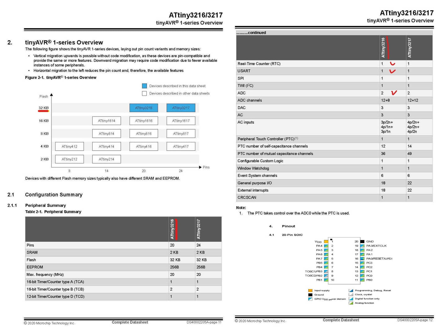
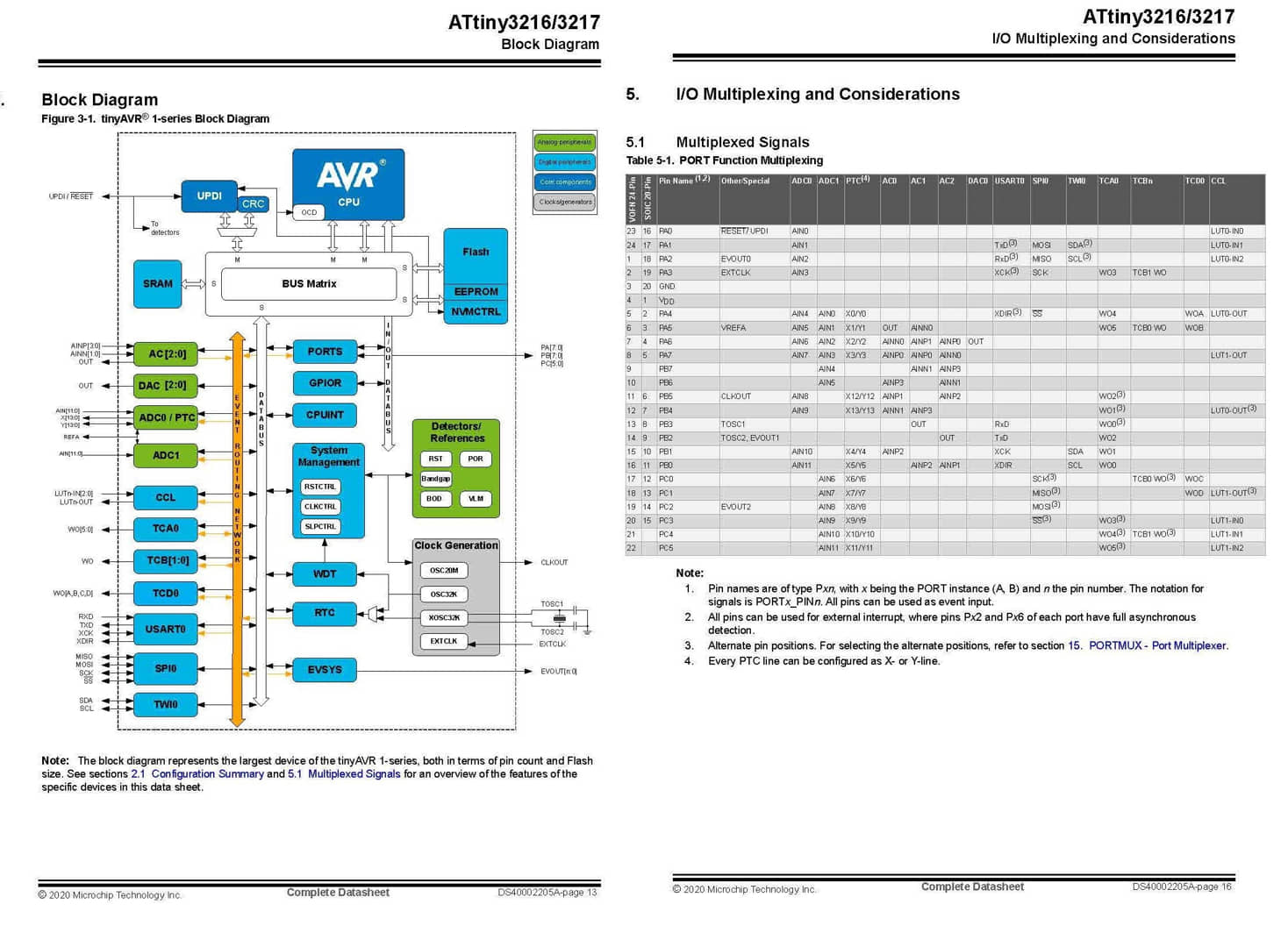
Block Diagram and I/O Multiplexing
This section contains the block diagram of the microcontroller system, how the parts of the microcontroller are connected and work. It also includes port mapping (I/O Multiplexing) to see what ports are available and what their functions are. This we need to see what certain ports can be used for (eg as analog inputs, and as UPDI, or also sometimes functioned as PWM, etc.).
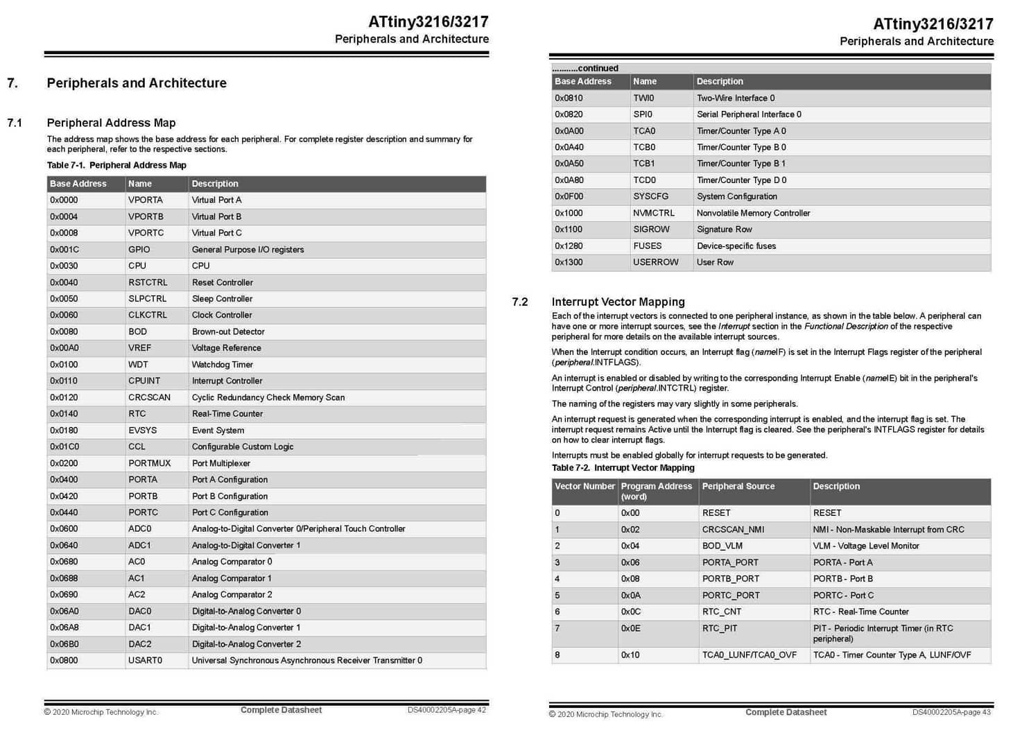
- Peripheral Architecture In Peripheral Architecture we can see the existing ports along with the addresses used. we can see for addressing when we will use a certain pin according to its function.
-
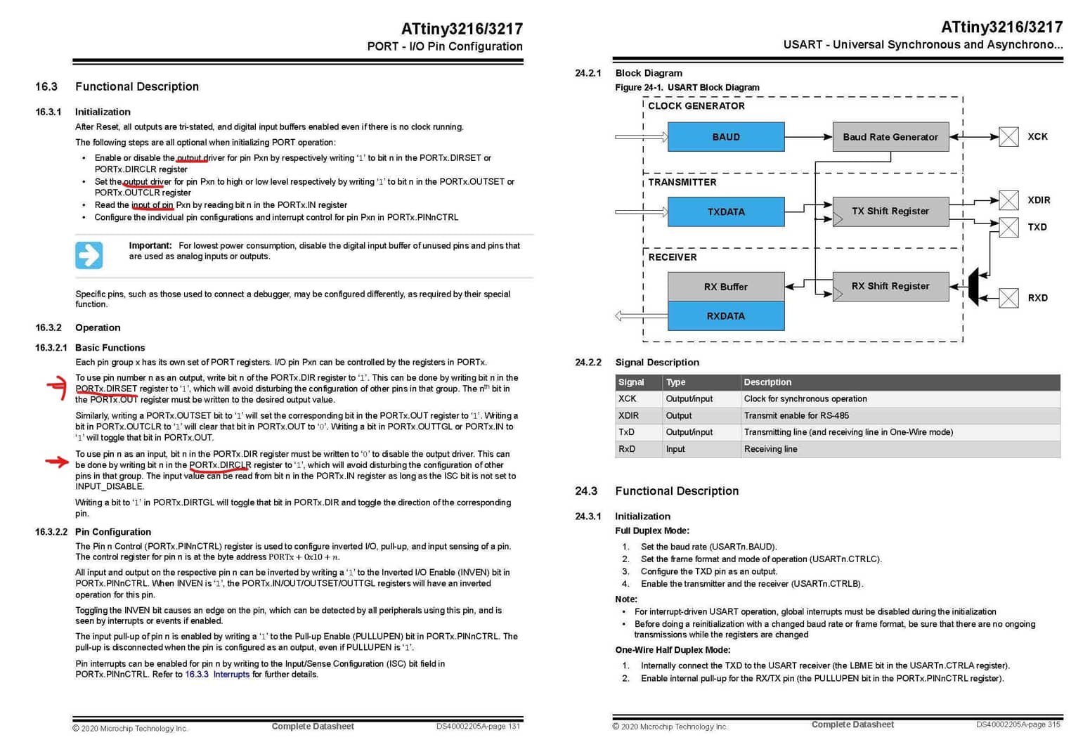
Port I/O Configuration, and USART
This section describes the I/O port configuration and how to use this port when programming, including the definition of the serial port
-
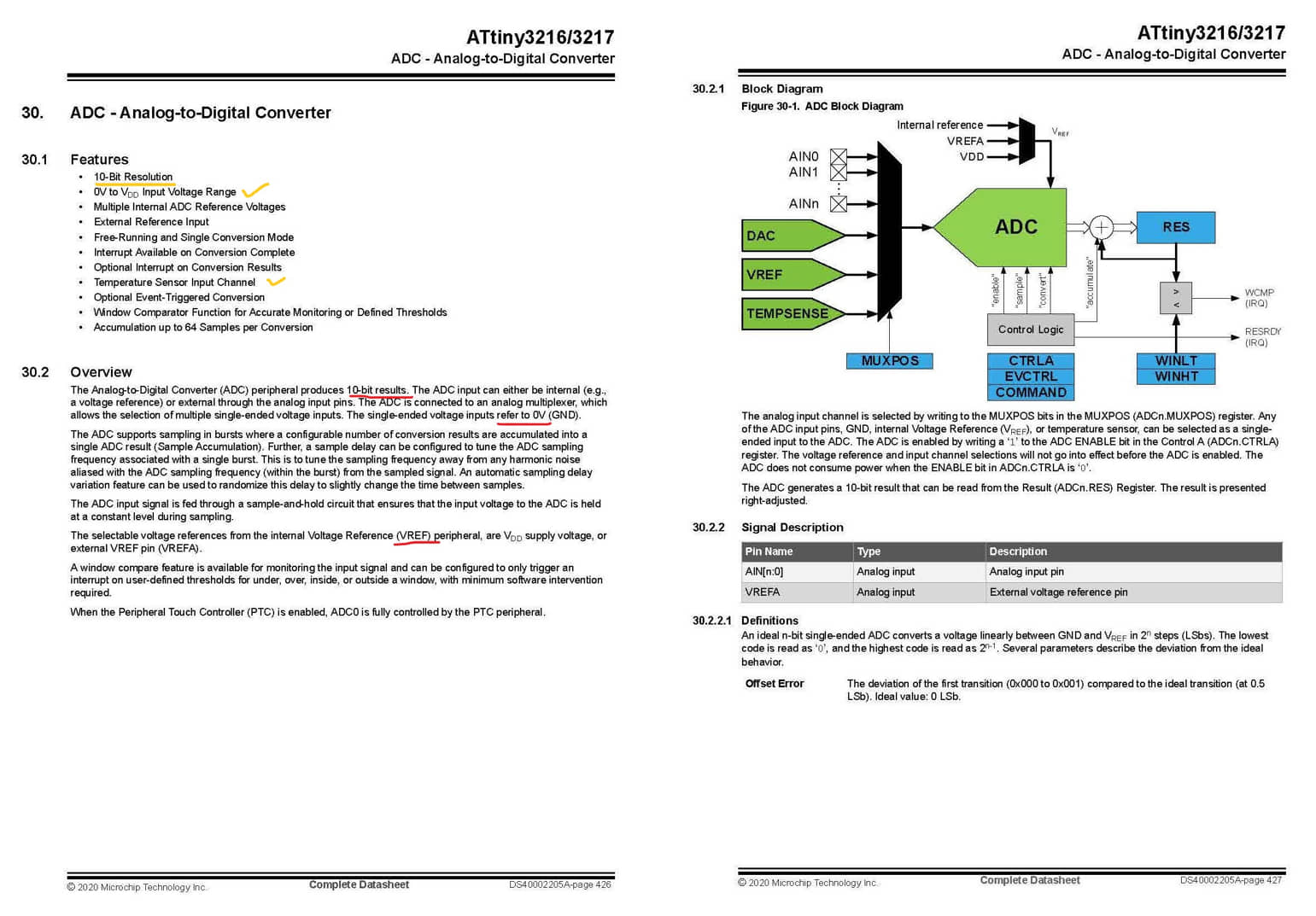
ADC (analog to digital converter)
This port will be used as an analog to digital data processor. the attiny-3128 has 2 10bit channels (there are 1024 dividers for accurate analog data read). For example in my final project I will use 1-2 analog sensors, so this chip is enough to use.
-
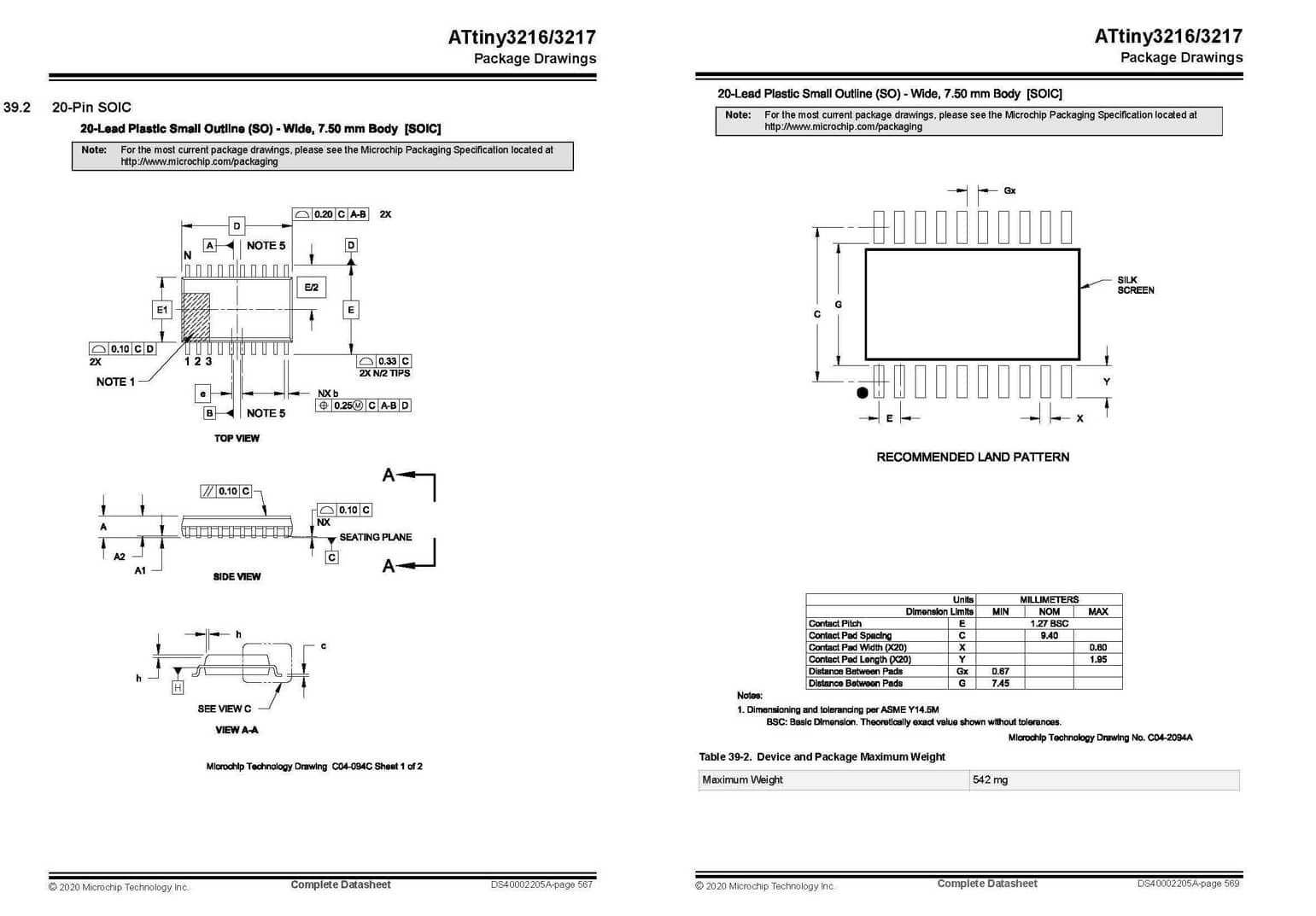
Drawing part
Component drawing is important to see component size, especially to determine when drawing PCB, how to position, leg size, gap size, etc.
Features :
- Max ADC Resolution (bits) : 10
- Number of ADCs : 2
- Program Memory Size (KB) : 32
- Number of Comparators : 3
- CPU Speed (MIPS/DMIPS) : 20
- Data EEPROM (bytes) : 256
- DigitalTimerQty_16bit : 3
- Max 8 Bit Digital Timers : 1
- Ethernet : None
- I2C : 1
- Program Memory Type : Flash
- mtrlcntrlinputcapture : 2
- ADC Channels : 16
- Low Power : No
- Operating Voltage : 1.8 - 5.5
- outputcomparatorPWM : 6
- Pin Count : 20
- SPI : 1
- Temp Range (°C) : -40 - 125
- USART : 1
Programming
This week I will try to do programming on my board ATtiny 3216 for the case of led blink and little bit variation with several programming type, such as:
- Arduino IDE
- AVR
- Python
- VR-GCC Tool-chain (pyupdi/pymcuprog)
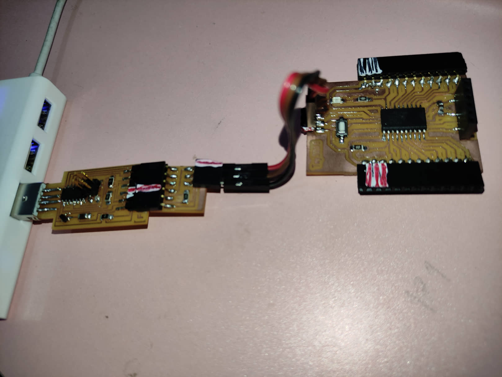
To do programming I need a programmer using the following SAMD11C:
Blink Programming
In this task I will try to make a simple program, namely “Blink” to make a LED light (pin 16) that turns on and off based on several programming models: Arduino IDE and AVR. everything is programmed and uploaded using Arduino IDE with the same configuration.
Programming with Arduino IDE
const int ledPin = 16; //difinition pin 16 as ledPin

void setup() {
  pinMode(ledPin, OUTPUT);
}

// the loop function runs over and over again forever
void loop() {
  digitalWrite(ledPin, HIGH);   // turn the LED on (HIGH is the voltage level)
  delay(1000);                       // wait for a second
  digitalWrite(ledPin, LOW);    // turn the LED off by making the voltage LOW
  delay(1000);                       // wait for a second
}
Programming with AVR
#include <avr/io.h>

#define LED_AVR PIN3_bm //PA3: LED pin

void setup() {
   PORTA.DIRSET = LED_AVR;
}

void loop() {
  PORTA.OUT |= LED_AVR;
  delay(1000);
  PORTA.OUT &= ~LED_AVR;
  delay(1000);
 }
or
#include <avr/io.h>

void setup() {
   PORTA.DIRSET = 0xff;
}

void loop() {
        PORTA.OUT=0b00001000;      // LED on
        delay(1000); // delay 1000ms (1 s)
        PORTA.OUT=0x00; //LED off
        delay(1000); // delay 1000ms (1 s)

} // end program
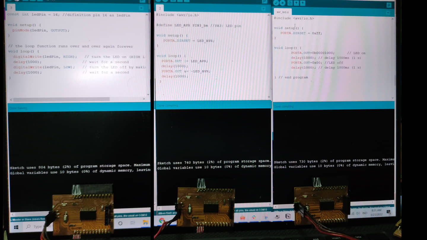
all three programs will be uploaded to ATtiny-3216
Programming with Python
This program is to turn the LED on and off (blink) using python via serial communication (interfacing) with the AT-Tiny 3216.
- first step we have to upload program to read the serial data to attiny-3216
- running python program to send the data via serial communication
-
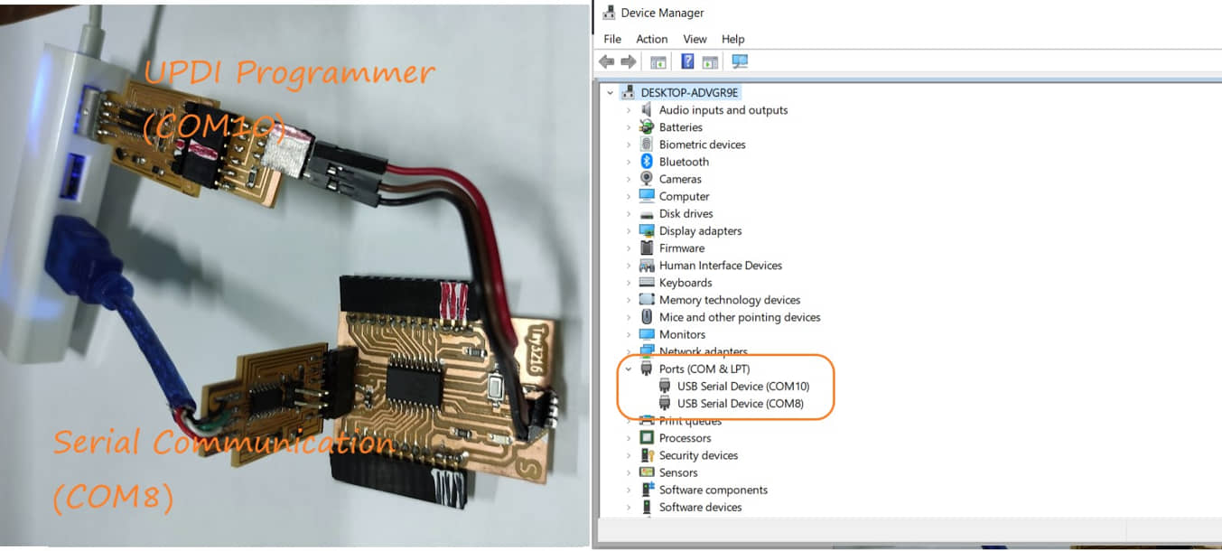
I’m using two SAMD11C boards that work as :
- programmer via UPDI (COM10)
- serial communication (COM8)
This configuration can be seen from the device manager in the windows system.
program upload to attiny-3216 :
byte data;
const int ledPin = 16;

void setup() {
  Serial.begin(9600); //initialize serial COM at 9600 baudrate
  pinMode(ledPin, OUTPUT); //make the LED pin (13) as output
  digitalWrite (ledPin, LOW);
}

void loop() {
while (Serial.available()){
  data = Serial.read();
}

if (data == '1'){
digitalWrite (ledPin, HIGH);
}
else if (data == '0'){
digitalWrite (ledPin, LOW);
}
}
Python Program for Blink
the source python program :
# arduino_blink.py

import serial
import time

ser = serial.Serial('COM8', 9600) # Define the serial port and baud rate.
time.sleep(2) # wait for the serial connection to initialize

while True:

        print("LED is on...")
        ser.write(b'1')
        time.sleep(1)
        print("LED is off...")
        ser.write(b'0')
        time.sleep(1)
we run the python program on computer by running the command :
py arduino_blink.py
the result :
Blink button
This program to turn on led with pressing button on attiny3216
AVR Programming
#include <avr/io.h>

#define LED_AVR PIN3_bm //PA3: LED pin
#define BUTTON_AVR PIN4_bm //PA6: Button pin

void setup() {

   PORTA.DIRSET = LED_AVR;     // use LED_AVR as an output
   PORTA.DIRCLR = BUTTON_AVR;  // use BUTTON_AVR as an input
}

void loop() {
  bool state = PORTA.IN & BUTTON_AVR; // read the state of a pin
  switch(state) {
    case 0:
    PORTA.OUT |= LED_AVR;
    break;
    case 1:
    PORTA.OUT &= ~LED_AVR;
    break;
    default:
    PORTA.OUT |= LED_AVR;
    break;

  }
 }
the result :
Python Program for Keyboard Blink
This program will control the led from the keyboard using python programming. The MCU configuration is the same as in the “blink” program using two SAMD11Cs that function as UPDI programmers and serial communication (need to check the position of the COM port). Programs uploaded on ATtiny3216 are the same as on “blink”. While the source of the python program is as follows:
# arduino_LED_key.py

import serial
import time

# Define the serial port and baud rate.
# Ensure the 'COM#' corresponds to what was seen in the Windows Device Manager
ser = serial.Serial('COM10', 9600)

def led_on_off():
    user_input = input("\n Type on / off / quit : ")
    if user_input =="on":
        print("LED is on...")
        time.sleep(0.1)
        ser.write(b'1')
        led_on_off()
    elif user_input =="off":
        print("LED is off...")
        time.sleep(0.1)
        ser.write(b'0')
        led_on_off()
    elif user_input =="quit" or user_input == "q":
        print("Program Exiting")
        time.sleep(0.1)
        ser.write(b'0')
        ser.close()
    else:
        print("Invalid input. Type on / off / quit.")
        led_on_off()

time.sleep(2) # wait for the serial connection to initialize

led_on_off()
result :
VR-GCC Tool-chain (pyupdi/pymcuprog)
The AVR GCC Toolchain is a collection of tools and libraries used to compile your code for the AVR microcontrollers. This collection includes a compiler, assembler, linker, and some libraries.
Most of the tools are based on efforts from the GNU community (GCC stands for GNU Compiler Collection), and some others are developed by Microchip.
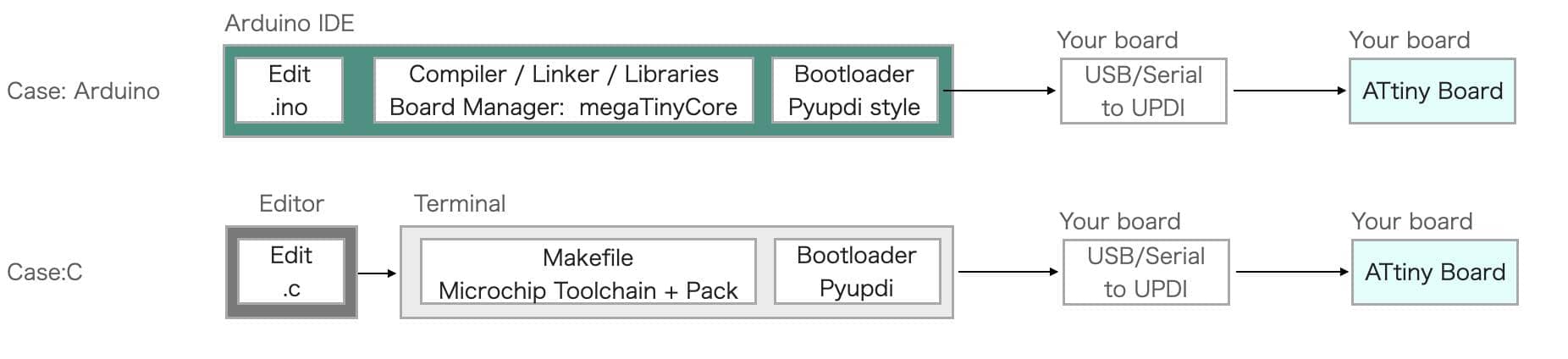
Programming Environment we will program the AVR not using the IDE but using the GCC-based toolchain. workflow programming is described in this image (source: kamakura)
In this task I will use the Windows 10 operating system, before programming on ATtiny-3216, we need to prepare the following steps:
- Install the
pyupdi(refer to Tiny AVR series) -
Download the MicroChip Toolchain
- Select the Toolchains for AVR® Microcontrollers (MCUs) program according to the operating system used, download it
- extract files
- move / put the extract to the folder C: Program Files (x86)
-
Download ATtiny_DFP atpack;
- change the extension file to zip, and extract the file to c:
-
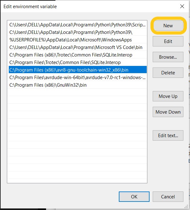
Update the PATH (“Environment Variables”) :
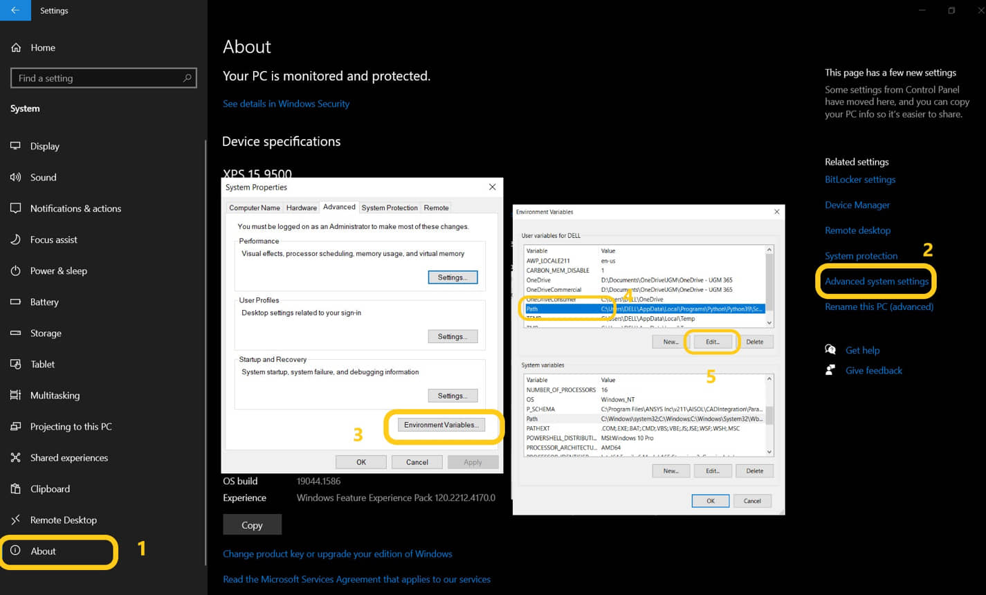
we need to update the path on the system in windows 10 so that the installation can be accessed directly. To add “Environment Variables”, we need to go to : Settings - Advanced System Settings . select the Advanced Tab, click “Environment Variables”. In the User Variable “PATH” add a new value for (adjust the location where we install / put the folder):
- C:\Program Files\avr8-gnu-toolchain\bin
- C:\Program Files (x86)\GnuWin32\bin
Check the installation
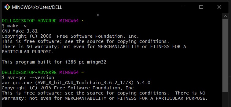
after all the applications are installed, we need to check if it can run. Open the git bash and enter the following command and press the “Enter”
make
make -v
avr-gcc
avr-gcc --version
create the C and make files
The c program that will be uploaded on attiny-3216 was made in c language first. while the make file is used to define the parameters used for the upload programming process. As an example we will use the “blink” program that has been made by Neils, but we need to modify it a bit.
- place both files in the working folder.
- open git bash and change directory to working folder (where the two files were)
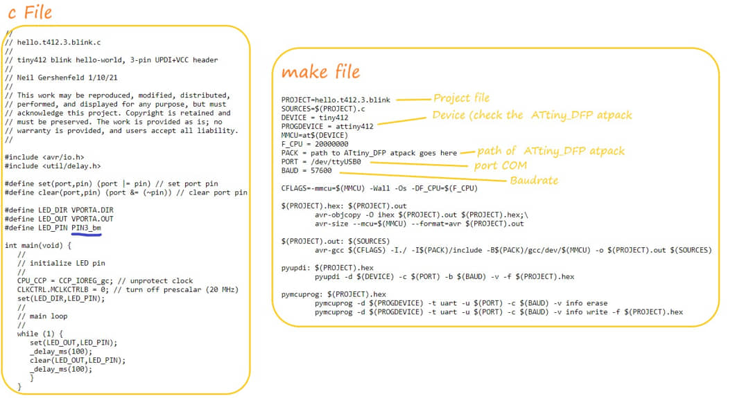
run the following command in your shell:
make -f hello.t3216.blink.make
make -f hello.t3216.blink.make pyupdi
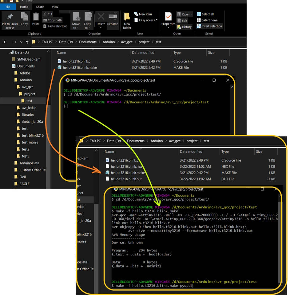
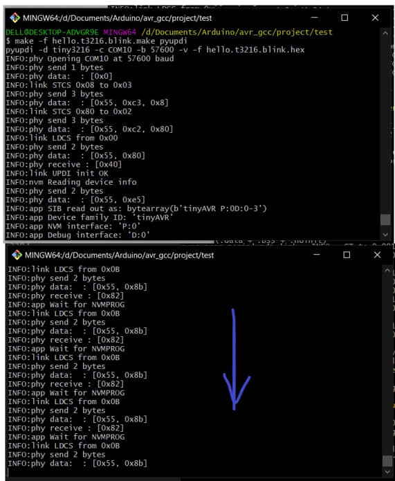
when you run make, it will generate HEX and OUT files. Hex file will be uploaded to MCU with pyupdi command
when running pyupdi, the command on the terminal runs continuously (doesn’t stop). the led is not lit, there is no indication that the hex program can be uploaded to the chip. Looks like this command didn’t work.
After I asked the instructor and looked for a discussion about pyupdi, it turns out that currently pyupdi is no longer maintained. So the alternative is to use Python MCU programmer pymcuprog.
- Install using pip from terminal:
pip install pymcuprog
if you have previously succeeded in generating a hex file, then we just need to upload the hex using pymcuprog. run the following command:
make -f hello.t3216.blink.make pymcuprog
Other Program : Running LED
I tried to make another program that is for running led. Previously I have made a series of LEDs that will be connected to PortA attiny3216. This program will shift the high value on the PartA output pin so that it will make the LED running. because pin0 is used as UPDI, the output data position is changed to PortB.5. We can change the speed of running led by changing the value of variable t.
#include <avr/io.h>
#include <util/delay.h>

const int t = 10;

int main(void) {
   PORTA.DIRSET = 0xff;
   PORTB.DIRSET = 0xff;

while (1)  {
// PORTA.OUT=0b11111110;
// _delay_ms(t);
 PORTA.OUT=0b11111101;
 _delay_ms(t);
 PORTA.OUT=0b11111011;
 _delay_ms(t);
 PORTA.OUT=0b11110111;
 _delay_ms(t);
 PORTA.OUT=0b11101111;
 _delay_ms(t);
 PORTA.OUT=0b11011111;
 _delay_ms(t);
 PORTA.OUT=0b10111111;
 _delay_ms(t);
 PORTA.OUT=0b01111111;
 _delay_ms(t);


 PORTA.OUT=0b01111111;
 _delay_ms(t);
 PORTA.OUT=0b10111111;
 _delay_ms(t);
 PORTA.OUT=0b11011111;
 _delay_ms(t);
 PORTA.OUT=0b11101111;
 _delay_ms(t);
 PORTA.OUT=0b11110111;
 _delay_ms(t);
 PORTA.OUT=0b11111011;
 _delay_ms(t);
 PORTA.OUT=0b11111101;
 _delay_ms(t);
// PORTA.OUT=0b11111110;
// _delay_ms(t);

 PORTB.OUT=0b00001111;
 _delay_ms(t);
 PORTB.OUT=0b11110000;
 _delay_ms(t);
 }
}
References
- Kamakura : Week 8 - Embedded Programming
- Embedded Programming
- Kamakura : Embedded Programming
- ATtiny-3216 Datasheet
- Using the GNU AVR toolchain on Windows 10
- Python MCU programmer
- The AVR GCC Toolchain
- AVR GCC Toolchain – Setup for Windows
Documentation Files
- Arduino IDE blink - tny3216
- AVR1 blink - tny3216
- AVR2 blink - tny3216
- Arduino blink for Python - tny3216
- Python for Blink - tny3216
- Python for Keyboard Blink - tny3216
- hello.t3216.blink.c
- hello.t3216.blink.make
- C for Running LED - tny3216
- make file for Running LED
Lessons learned (week 8 : Embedded programming):
- Understanding several type of architecture of MCU
- Understand how to use and read the datasheet, and select the MCU according to the datasheet
- Understanding several type of programming model for MCU like Arduino IDE, AVR, AVR GCC
- Understanding and applying the programming for MCU