10. Output devices
Week 10 : To do checklist
- Learn about pin assignment of MCU for output (Arduino Uno and ATtiny 3128)
- Individual Practice
- Read the datasheet of each output device (LED, LCD Display, Oled, TFT Display, Motor DC, stepper, Servo)
- Programming MCU to running the output device (ATtiny 3128 and Arduino for comparison)
- add the sample input device (sensor) and display the results to the output device
- Group work
- check the power consumption of an output device
- Repo to push group work (Kamakura) 2022
- Continue the final Project Process
- Documentations
Assignment (week 10):
Individual assignment:
- add an output device to a microcontroller board you’ve designed,
- and program it to do something
Group assignment:
- measure the power consumption of an output device
This week I worked on Output devices
Please click the button for Group Assignment
This week I tried to make a program for several output devices, including:
- LED
- LCD Display 16x2
- LCD 1.3” 128x64 . OLED
- 2.2 Inch TFT Module SPI LCD HD 240X320
- DC Motor
- Servo Motor
- Stepper Motor
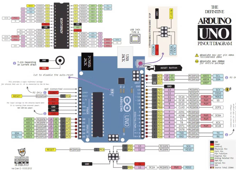
To program this output device I use two kinds of MCU, namely Arduino Uno and ATtiny 3216 (my development board at week 6)
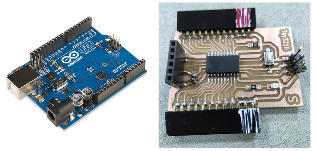
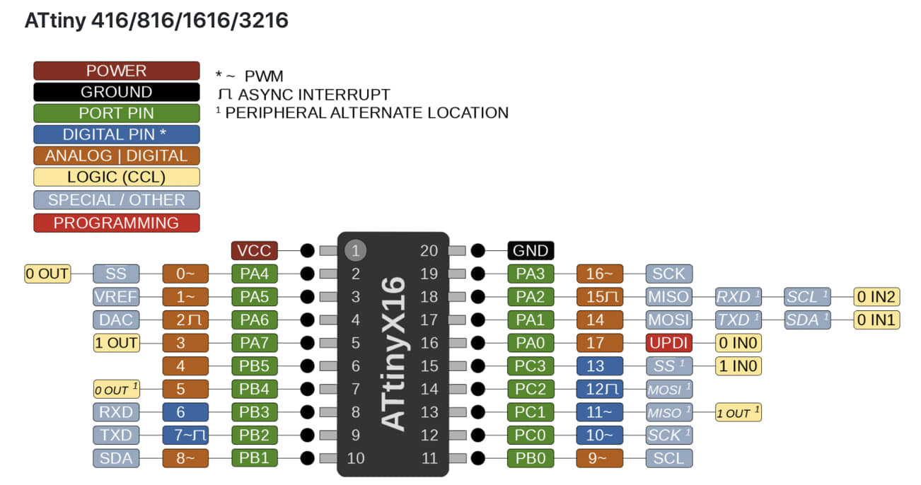
what needs to be understood is the pin assignment of each MCU.
LED (Light Emitting Diode)
LED is the simplest output device. LED is a semiconductor diode (anode-cathode) that produces light. The position and timing of the LEDs can be combined so that they can be used for display manipulation.
Running LEDs
This device has an 8-bit output in the form of an LED. we can program for pin checking using this device. In the program that I made I use Port A.1:7 pins (because A.0 pins are used for UPDI) and Port B.5.
This program is to make a running led, the led will light up alternately with a time that we can set by changing the value of t.
#include <avr/io.h>
#include <util/delay.h>

const int t = 10;

int main(void) {
   PORTA.DIRSET = 0xff;
   PORTB.DIRSET = 0xff;

while (1)  {
// PORTA.OUT=0b11111110;
// _delay_ms(t);
 PORTA.OUT=0b11111101;
 _delay_ms(t);
 PORTA.OUT=0b11111011;
 _delay_ms(t);
 PORTA.OUT=0b11110111;
 _delay_ms(t);
 PORTA.OUT=0b11101111;
 _delay_ms(t);
 PORTA.OUT=0b11011111;
 _delay_ms(t);
 PORTA.OUT=0b10111111;
 _delay_ms(t);
 PORTA.OUT=0b01111111;
 _delay_ms(t);


 PORTA.OUT=0b01111111;
 _delay_ms(t);
 PORTA.OUT=0b10111111;
 _delay_ms(t);
 PORTA.OUT=0b11011111;
 _delay_ms(t);
 PORTA.OUT=0b11101111;
 _delay_ms(t);
 PORTA.OUT=0b11110111;
 _delay_ms(t);
 PORTA.OUT=0b11111011;
 _delay_ms(t);
 PORTA.OUT=0b11111101;
 _delay_ms(t);
// PORTA.OUT=0b11111110;
// _delay_ms(t);

 PORTB.OUT=0b00001111;
 _delay_ms(t);
 PORTB.OUT=0b11110000;
 _delay_ms(t);
 }
}
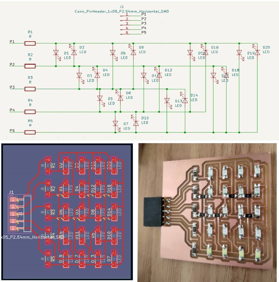
Charlieplexing LEDs
Charlieplexing (also known as tristate multiplexing, reduced pin-count LED multiplexing and complementary LED drive) is a technique for driving a multiplexed display in which relatively few I/O pins on a microcontroller are used e.g. to drive an array of LEDs (source : Wikipedia.
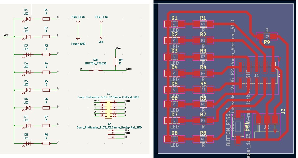
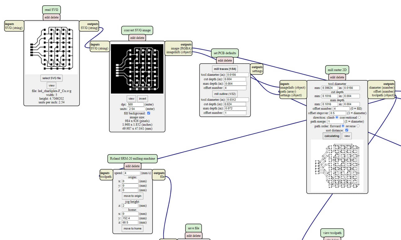
My Charlieplexing Circuit design adopted from Neil, but I modified only the LED output with 5 output pins, while I removed the MCU part and I used the MCU Development board that I previously made (Attiny 3216) in week 6. I redrawn the schematic and the position led refers to Neil’s board design. The schematic and the board also the Mods to create the PCB :
Note
This program is still very raw and random, it needs to adjust the LED position arrangement (Input or Output) and status (High/low) in order to produce a regular light direction or form a certain pattern.
The Source program :
#define A 0
#define B 1
#define C 2
#define D 3
#define E 4

#define PIN_CONFIG 0
#define PIN_STATE 1

#define LED_Num 20

int matrix[LED_Num][2][5] = {
  //           PIN_CONFIG                  PIN_STATE
  //    A       B       C      D      E         A     B    C    D    E
  { { OUTPUT, OUTPUT, INPUT, INPUT, INPUT }, { HIGH, LOW, LOW, LOW, LOW } },
  { { OUTPUT, OUTPUT, INPUT, INPUT, INPUT }, { LOW, HIGH, LOW, LOW, LOW } },
  { { OUTPUT, OUTPUT, OUTPUT, INPUT, OUTPUT }, { LOW, LOW, HIGH, LOW, LOW } },
  { { OUTPUT, OUTPUT, OUTPUT, INPUT, INPUT }, { LOW, LOW, LOW, HIGH, LOW } },
  { { INPUT, OUTPUT, OUTPUT, INPUT, OUTPUT }, { LOW, LOW, LOW, LOW, HIGH } },
  { { INPUT, OUTPUT, OUTPUT, INPUT, INPUT }, { HIGH, LOW, LOW, LOW, LOW } },
  { { INPUT, OUTPUT, OUTPUT, OUTPUT, OUTPUT }, { LOW, HIGH, LOW, LOW, LOW } },
  { { INPUT, OUTPUT, OUTPUT, OUTPUT, OUTPUT }, { LOW, LOW, HIGH, LOW, LOW } },
  { { INPUT, OUTPUT, INPUT, OUTPUT, INPUT }, { LOW, LOW, LOW, HIGH, LOW } },
  { { INPUT, OUTPUT, INPUT, OUTPUT, INPUT }, { LOW, LOW, HIGH, LOW, HIGH } },
  { { OUTPUT, INPUT, OUTPUT, OUTPUT, OUTPUT }, { HIGH, LOW, LOW, LOW, LOW } },
  { { OUTPUT, OUTPUT, OUTPUT, INPUT, INPUT }, { LOW, HIGH, LOW, LOW, LOW } },
  { { OUTPUT, INPUT, OUTPUT, INPUT, INPUT }, { LOW, LOW, HIGH, LOW, LOW } },
  { { OUTPUT, INPUT, OUTPUT, INPUT, INPUT }, { LOW, LOW, HIGH, LOW, LOW } },
  { { OUTPUT, INPUT, INPUT, OUTPUT, OUTPUT }, { LOW, LOW, LOW, LOW, HIGH } },
  { { INPUT, INPUT, INPUT, OUTPUT, INPUT }, { HIGH, LOW, LOW, LOW, LOW } },
  { { INPUT, OUTPUT, INPUT, OUTPUT, OUTPUT }, { LOW, HIGH, LOW, LOW, LOW } },
  { { INPUT, OUTPUT, INPUT, OUTPUT, OUTPUT }, { LOW, LOW, HIGH, LOW, LOW } },
  { { INPUT, INPUT, OUTPUT, OUTPUT, INPUT }, { LOW, LOW, LOW, HIGH, LOW } },
  { { INPUT, INPUT, OUTPUT, OUTPUT, OUTPUT }, { LOW, LOW, LOW, HIGH, HIGH } }
};

void lightOn( int led ) {
  pinMode( A, matrix[led][PIN_CONFIG][0] );
  pinMode( B, matrix[led][PIN_CONFIG][1] );
  pinMode( C, matrix[led][PIN_CONFIG][2] );
  pinMode( D, matrix[led][PIN_CONFIG][3] );
  pinMode( E, matrix[led][PIN_CONFIG][4] );
  digitalWrite( A, matrix[led][PIN_STATE][0] );
  digitalWrite( B, matrix[led][PIN_STATE][1] );
  digitalWrite( C, matrix[led][PIN_STATE][2] );
  digitalWrite( D, matrix[led][PIN_STATE][3] );
  digitalWrite( E, matrix[led][PIN_STATE][4] );
}

void setup() {}

void loop() {
  for( int l = 0; l < LED_Num; l++ ) {
    lightOn( l );
    delay( 1000 / LED_Num );
  }
}
The results :
I2C Scanner
Some of the equipment used for display uses serial I2C. The I2C module is a two-way serial communication standard using two channels specifically designed to send and receive data. The I2C system consists of SCL (Serial Clock) and SDA (Serial Data) channels that carry data information between the I2C and the controller.
Each device that uses I2C communication has its own address. We need to identify the address of the device that uses I2C so that the commands given are correct. We need to scan the I2C address using the following program:
#include <Wire.h> //include Wire.h library

void setup()
{
  Wire.begin(); // Wire communication begin
  Serial.begin(9600); // The baudrate of Serial monitor is set in 9600
  while (!Serial); // Waiting for Serial Monitor
  Serial.println("\nI2C Scanner");
}

void loop()
{
  byte error, address; //variable for error and I2C address
  int nDevices;

  Serial.println("Scanning...");

  nDevices = 0;
  for (address = 1; address < 127; address++ )
  {
    // The i2c_scanner uses the return value of
    // the Write.endTransmisstion to see if
    // a device did acknowledge to the address.
    Wire.beginTransmission(address);
    error = Wire.endTransmission();

    if (error == 0)
    {
      Serial.print("I2C device found at address 0x");
      if (address < 16)
        Serial.print("0");
      Serial.print(address, HEX);
      Serial.println("  !");
      nDevices++;
    }
    else if (error == 4)
    {
      Serial.print("Unknown error at address 0x");
      if (address < 16)
        Serial.print("0");
      Serial.println(address, HEX);
    }
  }
  if (nDevices == 0)
    Serial.println("No I2C devices found\n");
  else
    Serial.println("done\n");

  delay(5000); // wait 5 seconds for the next I2C scan
}
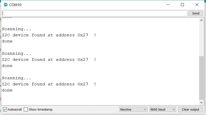
The I2C address that we get later we need to enter it in the next programming
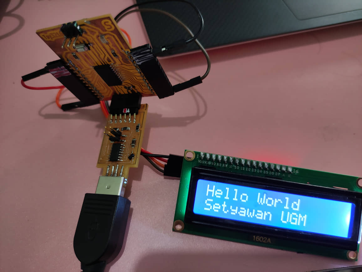
LCD Display 16x2
Test the display (hello world)
This program is to try to access a 16x2 LCD Display using an I2C connection. The use of I2C connection to save the need for pins in the MCU. This program will display the words “Hello World” on the first line and on the second line it will display “Setyawan UGM”.
#include  <Wire.h>
#include  <LiquidCrystal_I2C.h>

LiquidCrystal_I2C lcd(0x27, 16,2);  // Change 0x27 with I2C address was founded in scanner I2C

void setup()
{
  Serial.begin(9600);

  lcd.begin();

  lcd.backlight();
  delay(250);
  lcd.noBacklight();
  delay(250);
  lcd.backlight();

  lcd.setCursor(0,0);
  lcd.print("Hello World");
  delay(1000);
  lcd.setCursor(0,1);
  lcd.print("Setyawan UGM");
  delay(8000);
}

void loop()
{
}
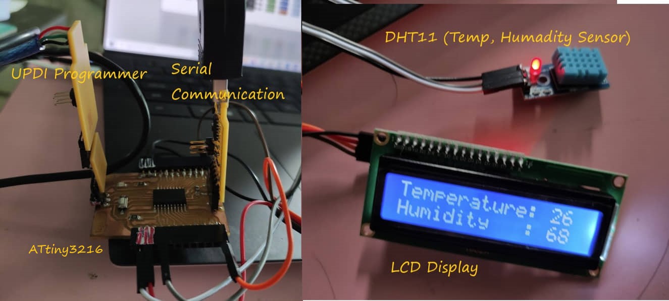
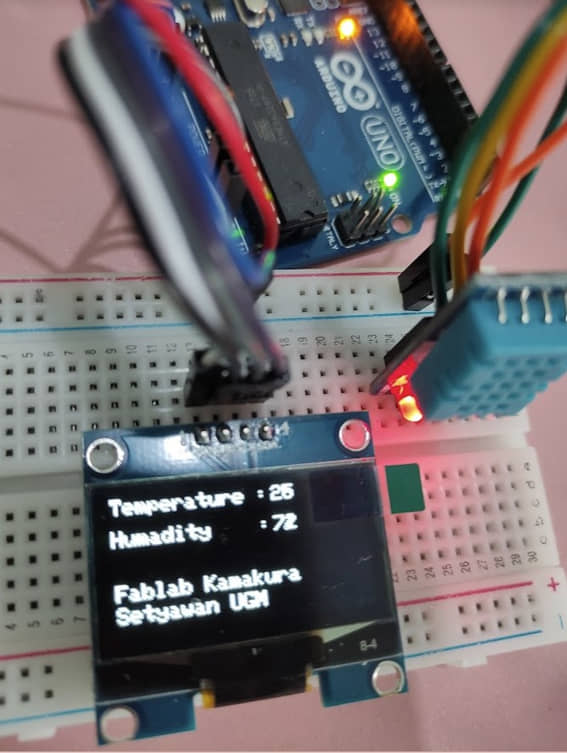
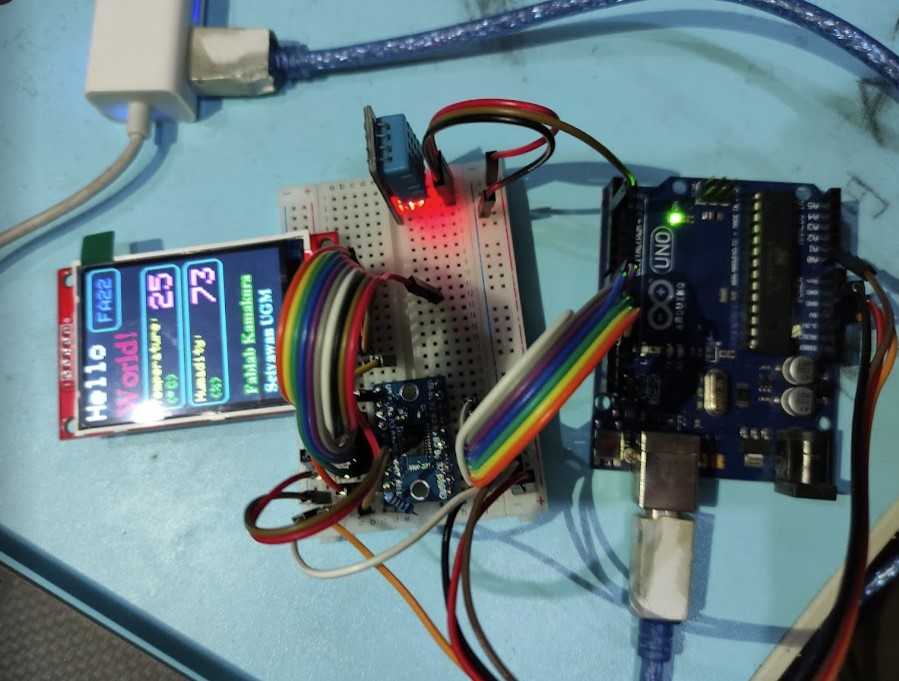
Display data from sensors (DHT11)
This program has combined the input data from the sensor which will display the readings on the LCD Display. The sensor used is DHT11 (temperature and humidity sensor). We need to first install the library DHT11. The reading results from DHT will be displayed on the display.
Circuit diagram :
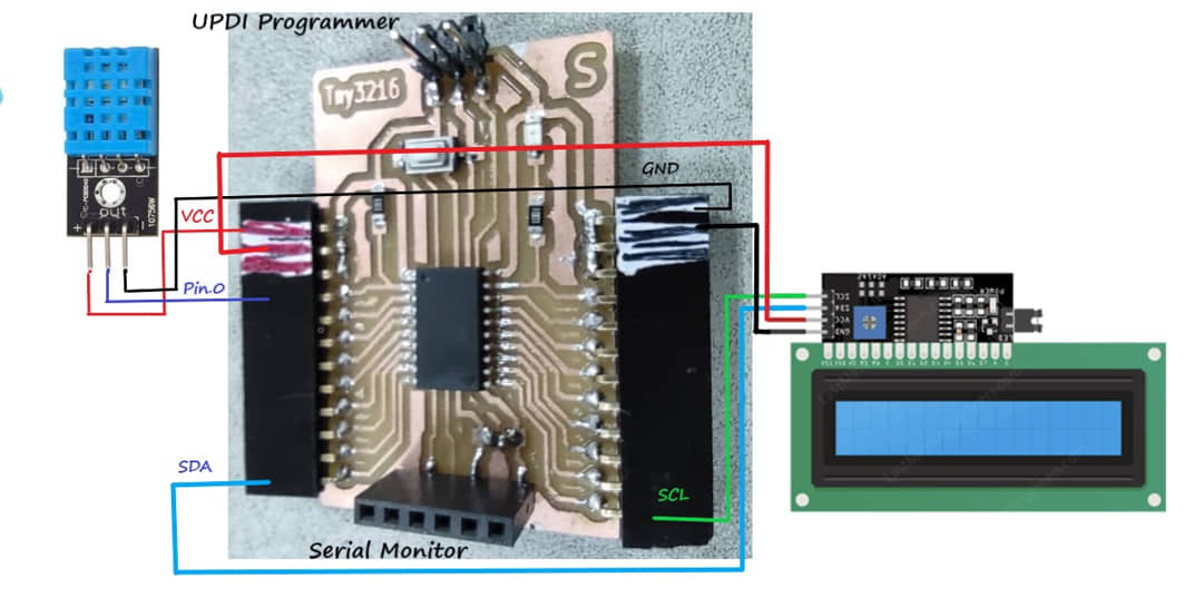
program source :
This program will display a splash of “Fablab Kamakura - Setyawan UGM” for 3 seconds. then read the DHT11 sensor data (one-wire) via Pin.0, then the data will be displayed to the LCD Display on the first line: Temperature (DHT.temperature) and the second line Humidity (DHT.humidity). It will also output temperature and humidity data via a serial monitor
#include  <Wire.h>
#include  <LiquidCrystal_I2C.h>
#include <DFRobot_DHT11.h>
DFRobot_DHT11 DHT;
#define DHT11_PIN 0

LiquidCrystal_I2C lcd(0x27, 16,2);

void setup()
{
  Serial.begin(115200);

  lcd.begin();

  lcd.backlight();
  delay(250);
  lcd.noBacklight();
  delay(250);
  lcd.backlight();

  lcd.setCursor(0,0);
  lcd.print("Fablab Kamakura");
  delay(1000);
  lcd.setCursor(0,1);
  lcd.print("Setyawan UGM");
  delay(3000);
  lcd.clear();
}

void loop()
{
  DHT.read(DHT11_PIN);
  Serial.print("temperature:");
  Serial.print(DHT.temperature);
  Serial.print("  humidity:");
  Serial.println(DHT.humidity);
  lcd.setCursor(0,0);
  lcd.print("Temperature:");
  lcd.setCursor(13,0);
  lcd.print(DHT.temperature);
  lcd.setCursor(0,1);
  lcd.print("Humidity   :");
  lcd.setCursor(13,1);
  lcd.print(DHT.humidity);
  delay(1000);

}
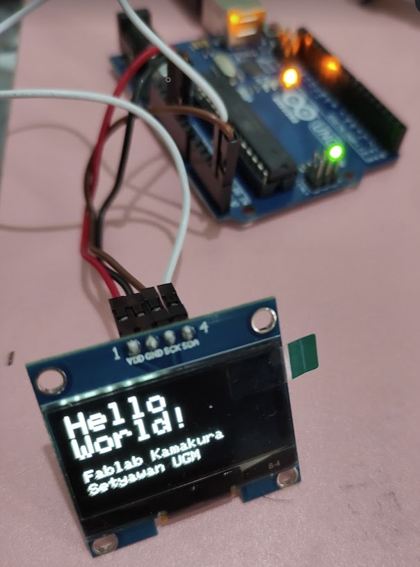
LCD Oled 1.3” 128x64
OLED is Organic Light-Emitting Diode or organic LED. This technology is used to produce good and high-quality light or images.
To use it we need to use a library. The Library can be downloaded:
The following is an example program for using OLED as a display. This program is a simple program to display the words “Hello World” and we can customize the text and the position.
#include <Wire.h>
#include <Adafruit_SH1106.h>

#define OLED_RESET 1
Adafruit_SH1106 display(OLED_RESET);

void setup()
{
  Serial.begin(9600);
  display.begin(SH1106_SWITCHCAPVCC, 0x3C);

  display.display();
  delay(1000);
  display.clearDisplay();
}

void loop()
{
  display.setTextSize(2);
  display.setTextColor(WHITE);
  display.setCursor(0,0);
  display.println("Hello");
  display.setTextSize(2);
  display.setTextColor(WHITE);
  display.println("World!");
  display.setTextSize(1);
  display.setCursor(1,40);
  display.print("Fablab Kamakura");
  display.setTextSize(1);
  display.setCursor(1,50);
  display.print("Setyawan UGM");
  display.display();
  delay(2000);
}
Display data from sensors
In this program we use an additional DHT11 sensor as data input and the results are displayed on the OLED Display.
Circuit :
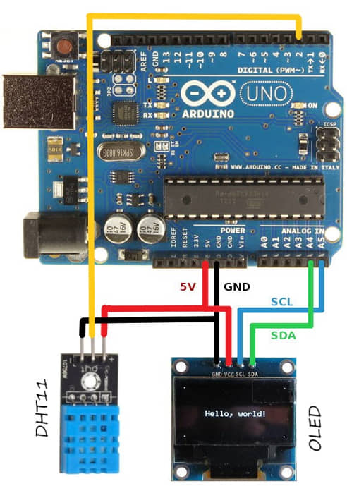
Program source:
#include <Wire.h>
#include <Adafruit_SH1106.h>
#include <DFRobot_DHT11.h>
DFRobot_DHT11 DHT;
#define DHT11_PIN 2
#define OLED_RESET 1
Adafruit_SH1106 display(OLED_RESET);

void setup()
{
  Serial.begin(9600);
  display.begin(SH1106_SWITCHCAPVCC, 0x3C);

  display.display();
  delay(300);
  display.clearDisplay();
}

void loop()
{
  DHT.read(DHT11_PIN);
  //  display.setTextSize(2);
  display.setTextSize(1);
  display.setTextColor(WHITE);
  display.setCursor(0,0);
  display.print("Temperature :");
  display.setCursor(80,0);
  display.println(DHT.temperature);
  display.setCursor(0,15);
  display.print("humidity    :");

  display.setCursor(80,15);
  display.setTextColor(WHITE);
  display.println(DHT.humidity);
  display.setTextSize(1);
  display.setCursor(1,40);
  display.print("Fablab Kamakura");
  display.setTextSize(1);
  display.setCursor(1,50);
  display.print("Setyawan UGM");
  display.display();
  delay(2000);
}
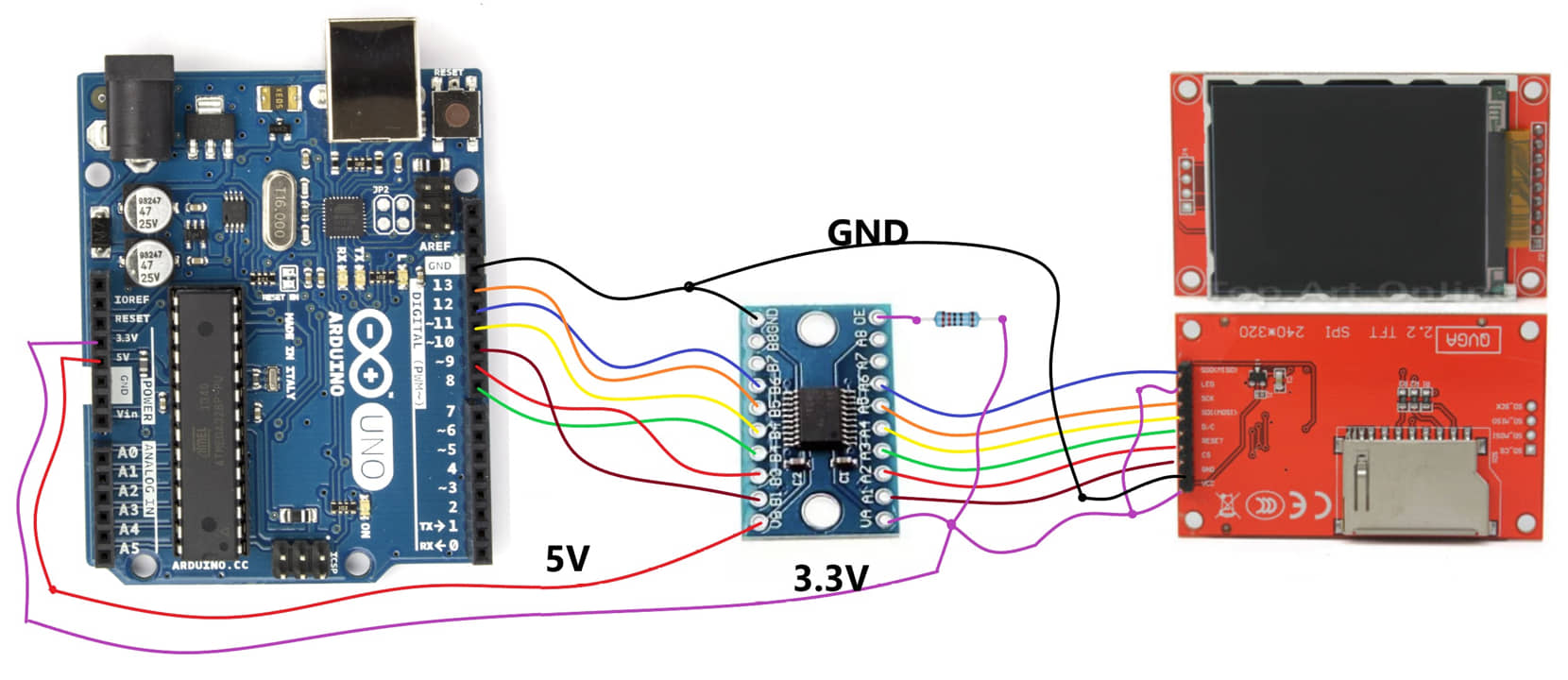
2.2 Inch TFT Module SPI LCD HD 240X320
TFT LCDs are liquid-crystal display modules with thin-film transistor technology. The TFT technology offers full RGB showcasing a range of colors and hues. Get rich colors, detailed images, and bright graphics from an LCD with a TFT screen.
To use this TFT module we need to use a library that can be downloaded at:
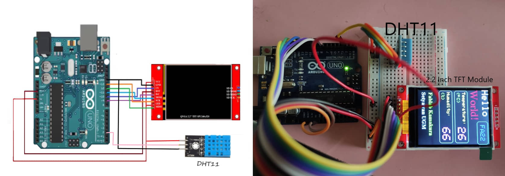
Sample program “Hello World with Input Sensors”
#include <Adafruit_GFX.h>    // Include core graphics library
#include <Adafruit_ILI9341.h> // Include Adafruit_ILI9341 library to drive the display
#include <DFRobot_DHT11.h>
DFRobot_DHT11 DHT;
#define DHT11_PIN 2

// Declare pins for the display:
#define TFT_DC 9
#define TFT_RST 8  // You can also connect this to the Arduino reset in which case, set this #define pin to -1!
#define TFT_CS 10
// The rest of the pins are pre-selected as the default hardware SPI for Arduino Uno (SCK = 13 and SDA = 11)
// Create display:
Adafruit_ILI9341 tft = Adafruit_ILI9341(TFT_CS, TFT_DC, TFT_RST);
#include <Fonts/FreeSerif24pt7b.h>  // Add a custom font
#include <Fonts/FreeSerifBold12pt7b.h>

int Variable1;  // Create a variable to have something dynamic to show on the display

void setup()  // Start of setup
{

  // Display setup:

  tft.begin();  // Initialize display

  tft.fillScreen(0x0000);  // Fill screen with black

  //tft.setRotation(0);  // Set orientation of the display. Values are from 0 to 3. If not declared, orientation would be 0,
                         // which is portrait mode.

  tft.setTextWrap(false);  // By default, long lines of text are set to automatically “wrap” back to the leftmost column.
                           // To override this behavior (so text will run off the right side of the display - useful for
                           // scrolling marquee effects), use setTextWrap(false). The normal wrapping behavior is restored
                           // with setTextWrap(true).


  // Write to the display the text "Hello":
  tft.setCursor(0, 0);  // Set position (x,y)
  tft.setTextColor(0xFFFF);  // Set color of text. First is the color of text and after is color of background
  tft.setTextSize(4);  // Set text size. Goes from 0 (the smallest) to 20 (very big)
  tft.println("Hello");  // Print a text or value

  // Start using a custom font:
  tft.setFont(&FreeSerif24pt7b); // Set a custom font
  tft.setTextSize(0);  // Set text size. We are using custom font so you should always set text size as 0

  // Write to the display the text "World":
  tft.setCursor(0, 80);  // Set position (x,y)
  tft.setTextColor(0xF800);  // Set color of text. We are using custom font so there is no background color supported
  tft.println("World!");  // Print a text or value

  // Write to the display the text "Fablab Kamakura":
  tft.setFont(&FreeSerifBold12pt7b);
  tft.setTextSize(0);
  tft.setCursor(10, 270);  // Set position (x,y)
  tft.setTextColor(0x07E0);  // Set color of text. We are using custom font so there is no background color supported
  tft.println("Fablab Kamakura");  // Print a text or value

    // Write to the display the text "Setyawan UGM":
  tft.setCursor(10, 301);  // Set position (x,y)
  tft.setTextColor(0x07FF);  // Set color of text. We are using custom font so there is no background color supported
  tft.println("Setyawan UGM");  // Print a text or value

  // Stop using a custom font
  tft.setFont();  // Reset to standard font, to stop using any custom font previously set

  tft.drawRoundRect(3, 95, 230, 60, 10, 0x07FF);  // Draw rounded rectangle (x,y,width,height,radius,color)
  tft.drawRoundRect(3, 165, 230, 60, 10, 0x07FF); // It draws from the location to down-right
  tft.drawRoundRect(140, 5, 100, 50, 10, 0x07FF);

}  // End of setup


void loop()  // Start of loop
{
  DHT.read(DHT11_PIN);

  // Write to the display the Variable1 with left text alignment:
  tft.setCursor(155, 20);  // Set position (x,y)
  tft.setTextColor(0x001F, 0x0000);  // Set color of text. First is the color of text and after is color of background
  tft.setTextSize(3);  // Set text size. Goes from 0 (the smallest) to 20 (very big)
  tft.println("FA22");  // Print a text or value

  tft.setCursor(10, 105);  // Set position (x,y)
  tft.setTextColor(0xFFE0, 0x0000);  // Set color of text. First is the color of text and after is color of background
  tft.setTextSize(2);  // Set text size. Goes from 0 (the smallest) to 20 (very big)
  tft.println("Temperature:");  // Print a text or value
  tft.setCursor(10, 130);
  tft.setTextColor(0x07E0, 0x0000);
  tft.println("(");
  tft.setCursor(20, 130);
  tft.println((char)247); // Print a text or value of symbol degree with char247
  tft.setCursor(35, 130);
  tft.println("C)");

  tft.setCursor(10, 175);  // Set position (x,y)
  tft.setTextColor(0xFFE0, 0x0000);  // Set color of text. First is the color of text and after is color of background
  tft.setTextSize(2);  // Set text size. Goes from 0 (the smallest) to 20 (very big)
  tft.println("humidity:");  // Print a text or value
  tft.setCursor(10, 200);
  tft.setTextColor(0x07E0, 0x0000);
  tft.println("(%)");

  tft.setCursor(165, 107);  // Set position (x,y)
  tft.setTextColor(0xF81F, 0x0000);  // Set color of text. First is the color of text and after is color of background
  tft.setTextSize(5);  // Set text size. Goes from 0 (the smallest) to 20 (very big)
  tft.println(DHT.temperature);  // Print a text or value


  tft.setCursor(165, 177);  // Set position (x,y)
  tft.setTextColor(0xF81F, 0x0000);  // Set color of text. First is the color of text and after is color of background
  tft.setTextSize(5);  // Set text size. Goes from 0 (the smallest) to 20 (very big)
  tft.println(DHT.humidity);  // Print a text or value

  // Stop using a custom font
  tft.setFont();  // Reset to standard font, to stop using any custom font previously set
  delay(500);

}  // End of loop
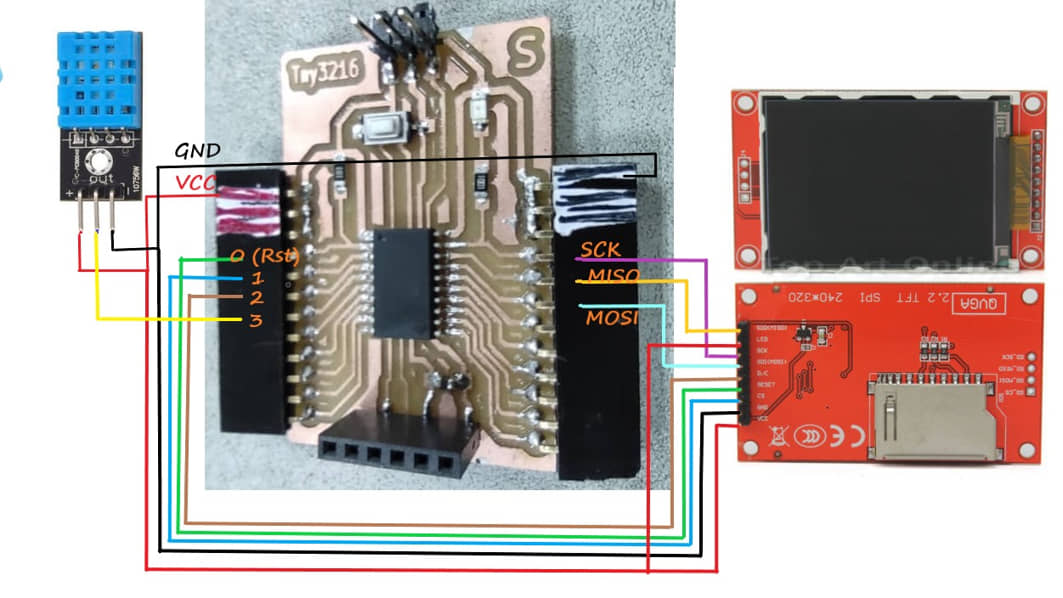
I’m also trying to use the ATtiny 3216 MCU to run this TFT Display. to note is the pin assignment of ATtiny3216. Circuit with ATtiny 3216 :
results:
Additional notes
When I did the above programming for the TFT Display, at first only a white screen appeared. From some references I get that by connecting (jumper) J1 can solve the problem earlier. And it turns out that after I connect the TFT display can light up.
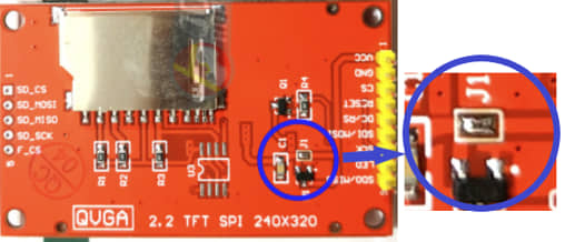
After reading some posts, connecting J1 will make the TFT and SD Card work at 5V. This can result in rapid damage or overheating of the TFT and SD Card on prolonged use. I tried to replace it by adding a TXS0108E 8 Channel Logic Level Converter. The connection between the MCU and the TFT is passed through a 3.3-5V Logic Level Converter IC.
The Logic Level Converter component requires a 3.3V supply. On my ATtiny 3216 MCU board I haven’t added an output for a 3.3V source, so to try this circuit I use Arduino UNO. The connection and the result are as follows:
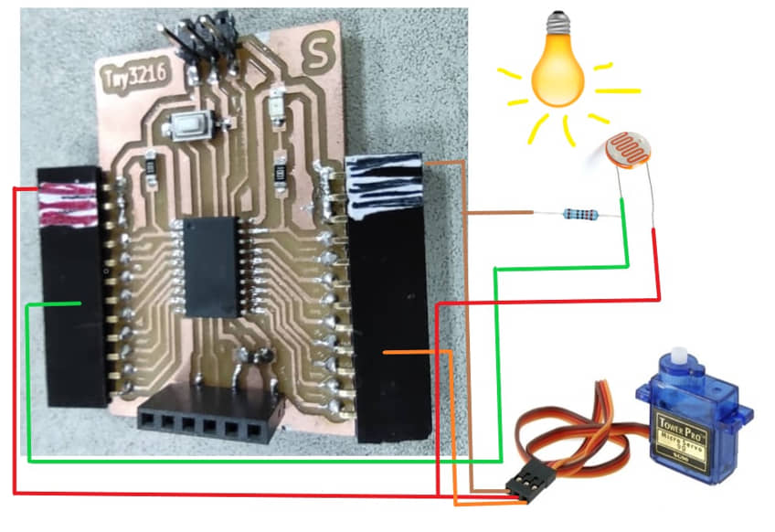
Servo Motor
Program with photoresistor to drive the Servo Motor to detect the Night and Day
I tried to use the input from the photoresistor sensor (analog sensor) to detect the value of the incoming light and then ordered the servo to rotate. The data received from the sensor is compared with a certain value to determine the “Day” or “Night” conditions. If the value is less than the set value then the servo will rotate at 0 degrees, while if it is more than the set value the servo will rotate at 90 degrees. Of course, the set value needs to be calibrated to the actual conditions.
#include <Servo.h> // servo library
Servo myservo; // servo variable

int pos = 0; // declaration vor angle 0
int ldr = 3; // analog pin 3
int nilai ;

void setup()
{
  myservo.attach(12); //servo pin
  pinMode(ldr,INPUT);
  Serial.begin(9600);
}

void loop()
{
  nilai=analogRead(ldr);
  Serial.print("LDR value :");
  Serial.print(nilai);
  if (nilai<300){  //decision for Night and Day
    myservo.write(90);
     Serial.println("--> Night");
  }
  else {
    myservo.write(0);
    Serial.println("--> Day");
  }
}
result :
References
- Kamakura : Week 10 - Output Device
- Output Devices - Kamakura local session
- Charliplexing
- Charlieplexing LEDs
- Monochrome OLED Breakouts
- 2.2” TFT Display
- Adafruit GFX Graphics Library
- Creating Custom Symbol Fonts for Adafruit GFX Library
- DHT sensor library
Documentation Files
- C for Running LED - tny3216
- make file for Running LED
- LCD World
- LCD with DHT11
- PCB trace Charliplex (svg)
- PCB interior Charliplex (svg)
- Charlieplex LED
- LCD Running Text
- OLED World
- OLED with DHT11
- Scanner I2C
- TFT ILI9341 for Ty3216
- Servo with photoresistor
- Attiny 3216 board trace (.svg)
- Attiny 3216 board interior (.svg)
- Attiny 3216 board hole (.svg)
- Attiny 3216 PCB KiCAD project (.zip)
- Charlieplexing PCB KiCAD project (.zip)
- LED output PCB KiCAD project (.zip)
Group assignment learning
- In the group assignment, we measure the power consumption of an output device
- Understanding the power consumption of an output device
Lessons learned (week 10 : Output Device):
- Understanding of pin assignment for MCU (Arduino UNO and ATtiny 3216)
- Understand how to program the output device for Arduino and ATtiny
- Understanding the power consumption of an output device