7. Computer controlled machining
Week 7 : To do checklist
- Learn and Practice running Big CBC Milling with safety procedurs
- Group work
- Learn CNC Milling process
- Test and running and characterizing the big CNC Milling
- Repo to push group work 2022
- Individual Practice
- Design the parts for CNC milling
- Mill the design
- Assembling the parts
- Continue the final Project Process
- Documentations
Assignment (week 7):
Group assignment:
- do your lab’s safety training
- test runout, alignment, fixturing, speeds, feeds, materials, and toolpaths for your machine
Individual assignment:
- make (design+mill+assemble) something big (~meter-scale)
- extra credit: don’t use fasteners or glue
- extra credit: include curved surfaces
This week I worked on Computer controlled machining
Please click the button for Group Assignment
Group assignment learning
- In the group assignment, we studied the characteristics big CNC Milling
- What is the best setting of our machine
- What can it do with machine cnc for wood
Design the Model
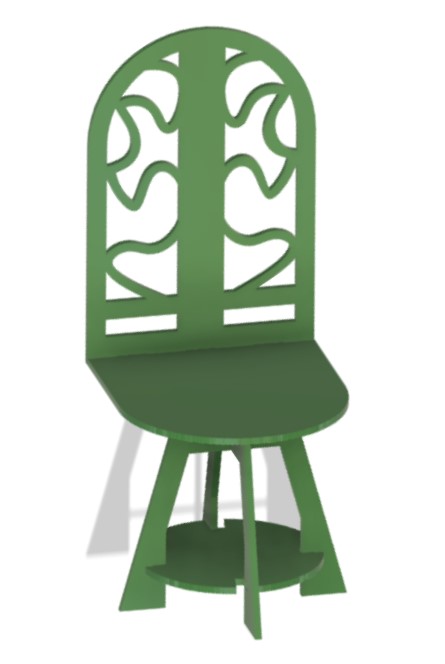
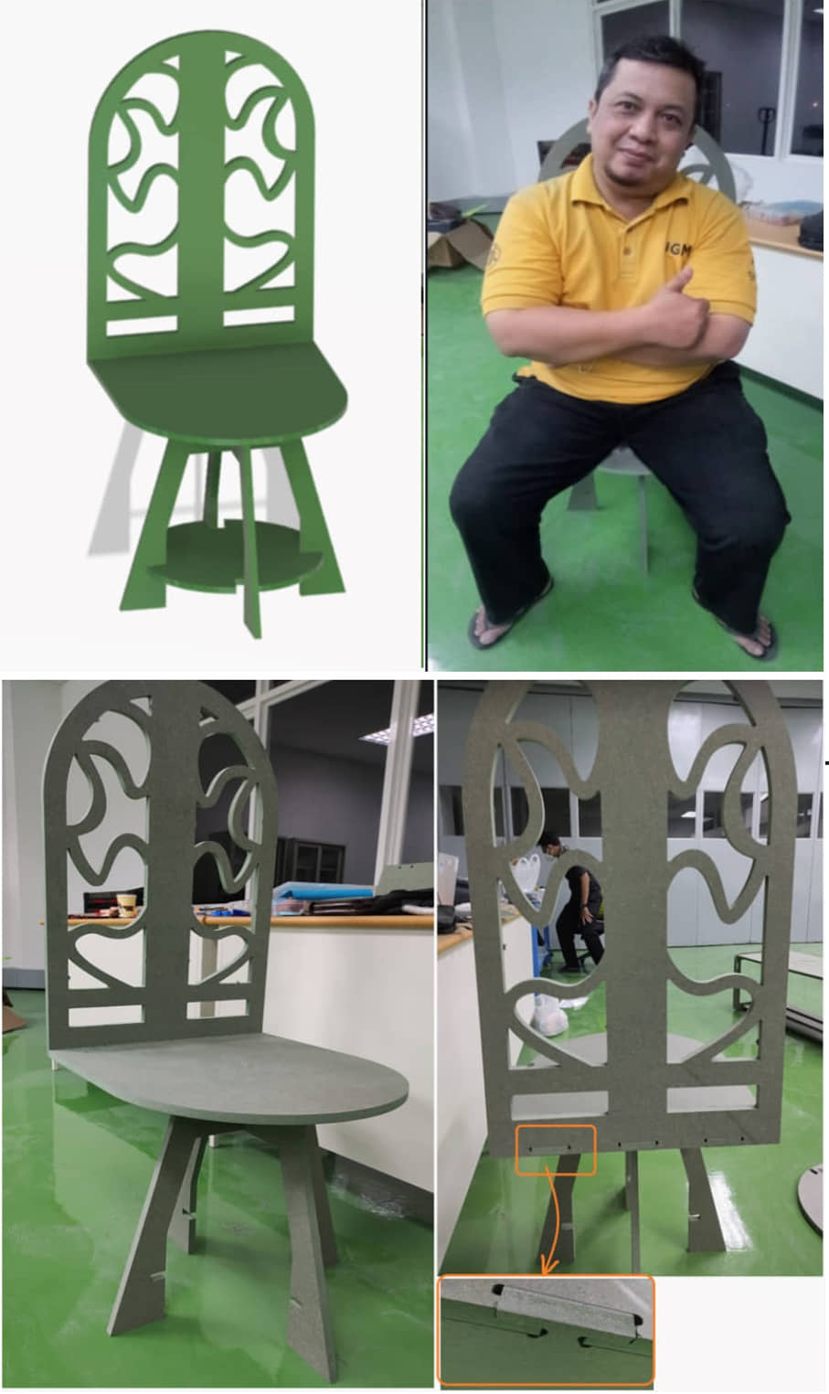
In this task I will make a chair with a height of about 1.2 m and a width of 0.5 m. This chair is made using MDF board material, with a thickness of 15 mm. There are several parts of this chair:
- chair legs
- leg brace
- seat cushion
- seat back
Several stages are described in the steps in the following documentation:
Create drawing with Fusion 360
To design the chair drawing, I used Fusion 360. Each part is sketched (2D). The resulting sketch is exported to a dxf file to be processed in CAM software (Cut 2D Pro).
-
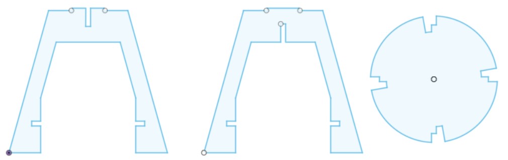
draw the legs
Chair legs have two pieces, to combine we use press-fit which we have learned previously. The effect of cutting (Kerf factor) needs to be considered, in this design the slots that we made we add each about 0.4 mm (0.2 - 0.6 mm) so that when paired it can be installed correctly.
detail :
-
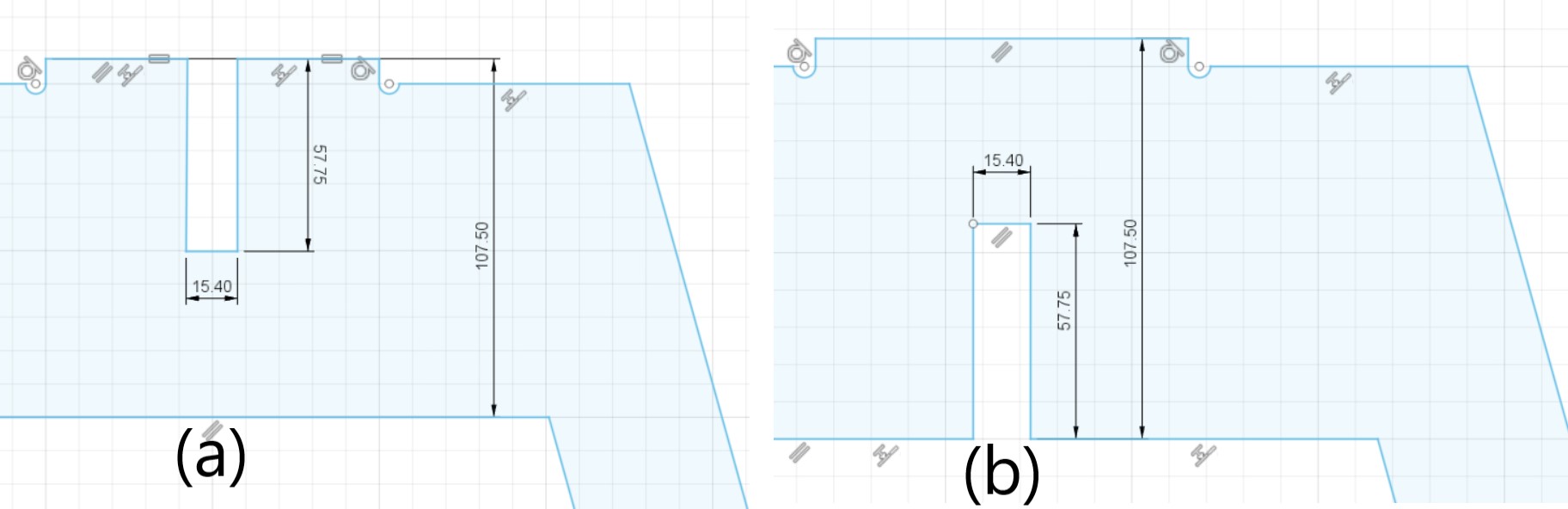
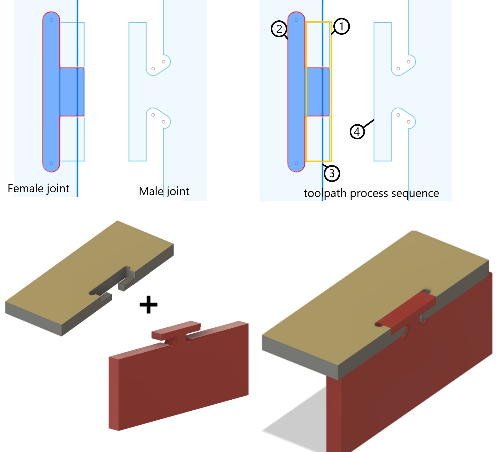
draw the cushion and chair back
While the cushion and chair back will be paired in a perpendicular direction. In the joining position, we make a join with the T model. This model will make the wooden pair lock each other and not be easily removed.
Joining parts for assembly
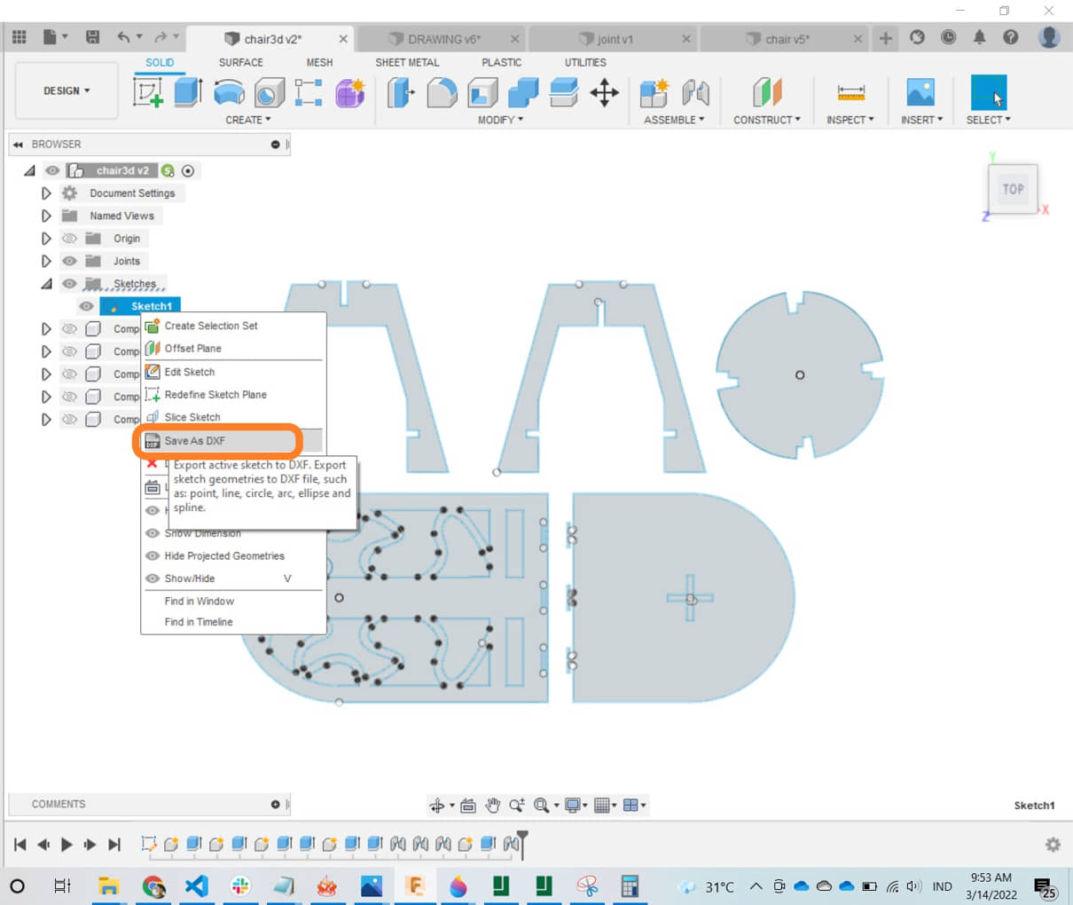
After all the sketches have been created, we can export the sketch to a DXF file to be processed in CAM software (Cut2D Pro), by “right clicking” on the sketch and save as DXF, save the file.
Preparing for Mill
Cut2D Pro
Cut2D Pro gives you the power to produce complex 2D patterns with profile, pocket, drill and inlay toolpaths. With unlimited job and toolpath size, true shape nesting & job set-up sheets. Cut2D Pro has easy to use vector drawing and editing tools with powerful 2D machining strategies for CNC routing, milling or engraving and provides a powerful but intuitive software solution for cutting parts on a CNC Router.
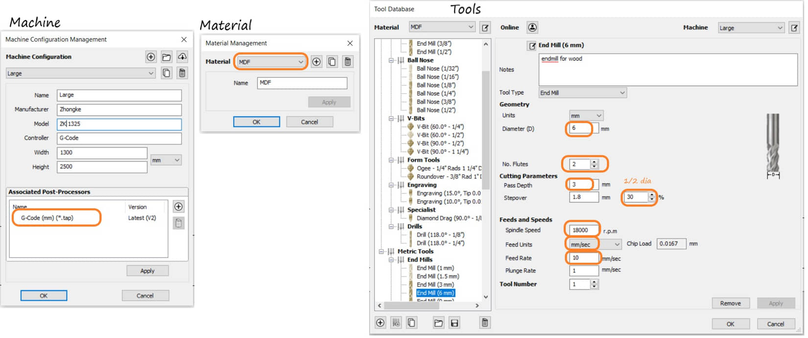
Setup the tool, material and Processor
For the first time installing Cut2D Pro, we are asked to install the machine and processor that we will use. At the same time we can also install the types of materials and tools that will be used. The machine we use is Zhongke ZK-1325.
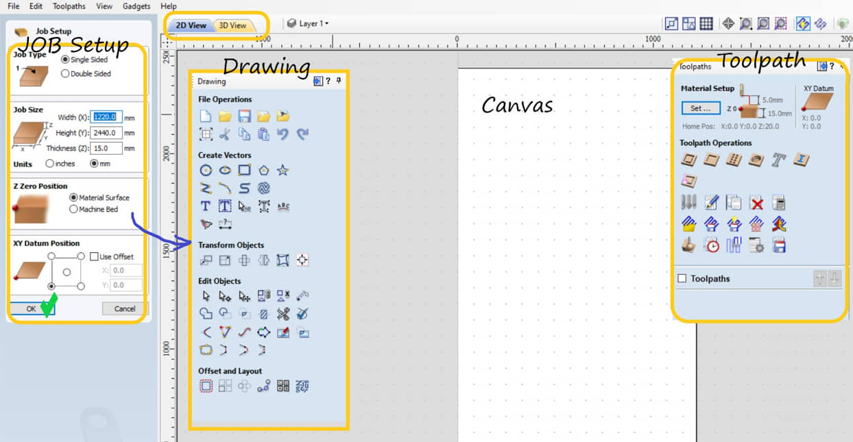
Preparing the CAM Process
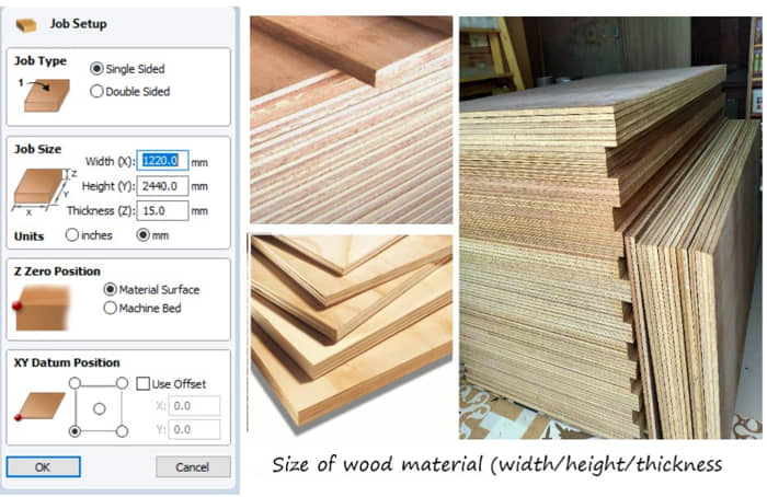
In this work I use two types of wood, namely multilayer plywood and MDF board. The real size of the board is 1220 mm x 2440 mm with a thickness of 15mm. This value we must enter into Job Setup on Cut2D Pro.
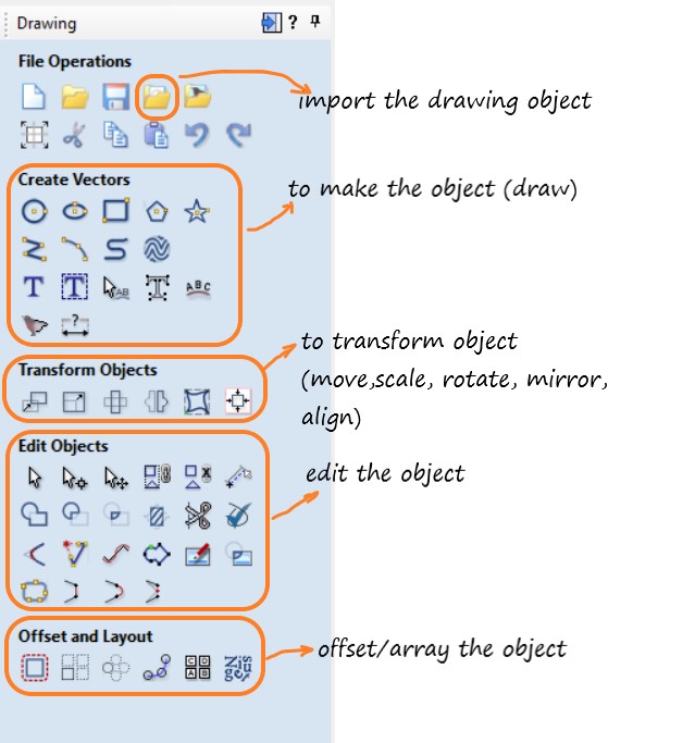
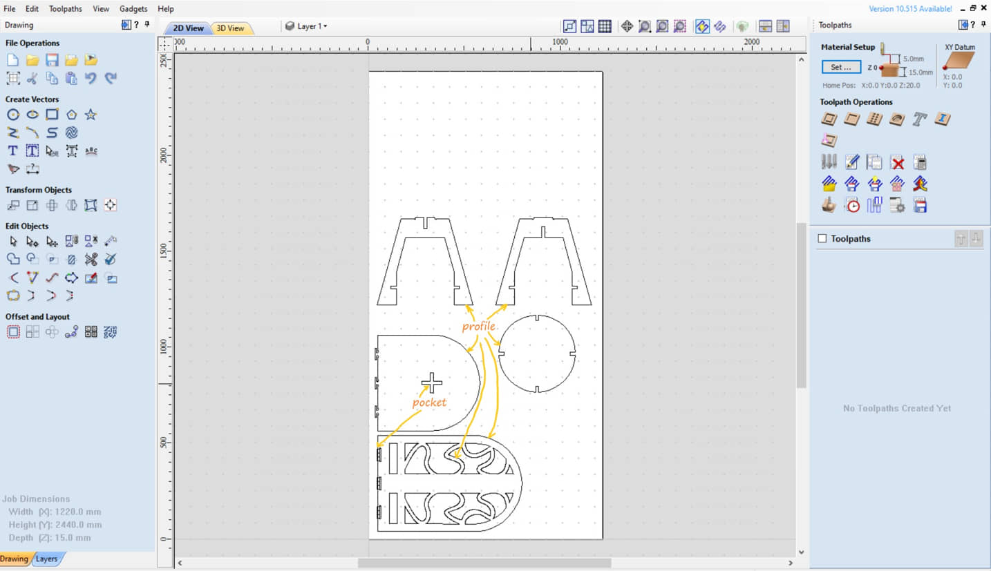
After determining the size of the Job Setup/material to be cut, then we can import the previously created drawing (dxf) via import vector.
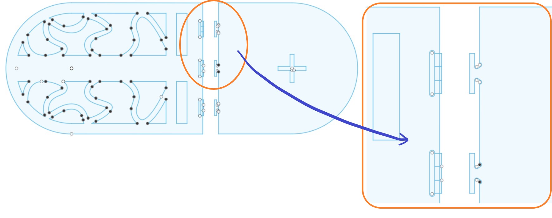
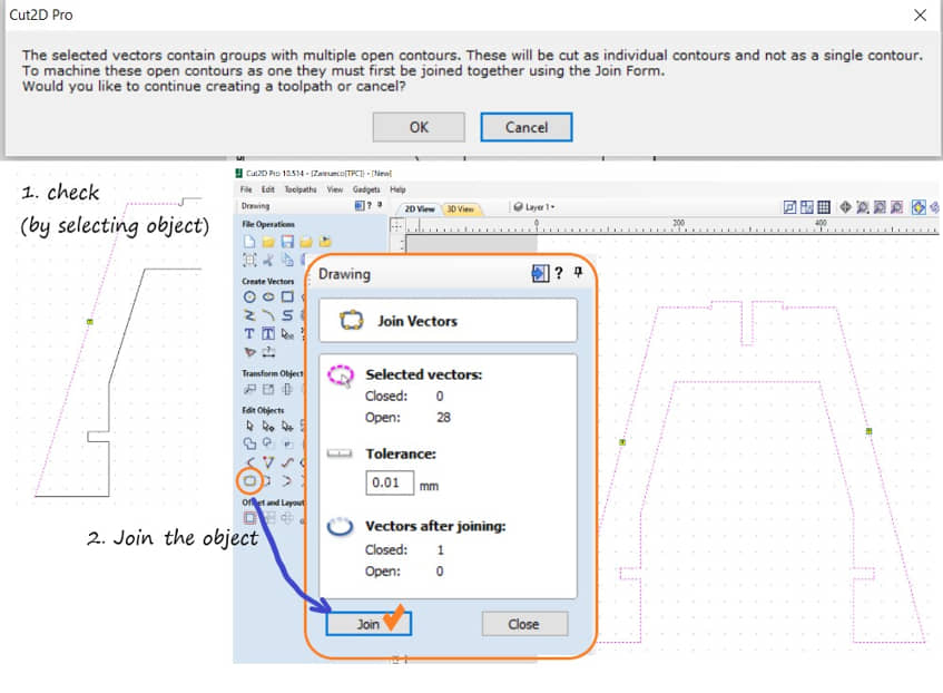
The sketch will be presented on the Cut2D Pro screen. To be able to do the toolpath, we have to make sure that the imported curves are :
- is a single curve (not overlapping each other)
- inter-curves are interconnected (unbroken/no gaps)
- all curves become one unit (join)
We can check by selecting the imported curve, whether it has joined, or is not connected or overlaps with the vector validator menu ![]() .
If there is a problem, sometimes we need to edit manually, for example: delete, add lines, or combine vectors (join).
.
If there is a problem, sometimes we need to edit manually, for example: delete, add lines, or combine vectors (join).
Create the toolpaths
If all the curves are fine then we can continue to create Toolpath. Toolpath creation can be for all curves (the same type of toolpath) or for individual curves.
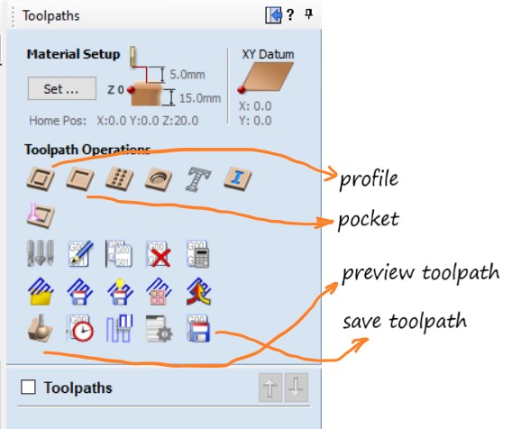
The most frequently used toolpath types are Profile and Pocket. Profile is used to define the tool to follow the contour of a certain curve, so that it can be used to cut with a certain depth. Whereas pocket is making a pocket or carving a certain area with a depth that we specify. We need to determine what toolpath operations will be performed on each curve we have created
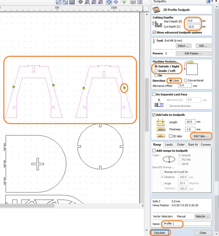
Create the profile
The profile is used to order the cutter to follow a curve path. This command is also used to cut (outline) based on the specified depth.
- we need to determine the depth of cut. if the depth is equal to the thickness of the board, it means this is a cutting process.
- we also need to determine the direction of movement with respect to the curve, to determine the cut on the inside or outside
- in this command there is also an additional menu, namely add tabs, which is to add a few retaining parts that function to keep the material being cut from coming off when it is cut.
- Run calculate to generate toolpath profile
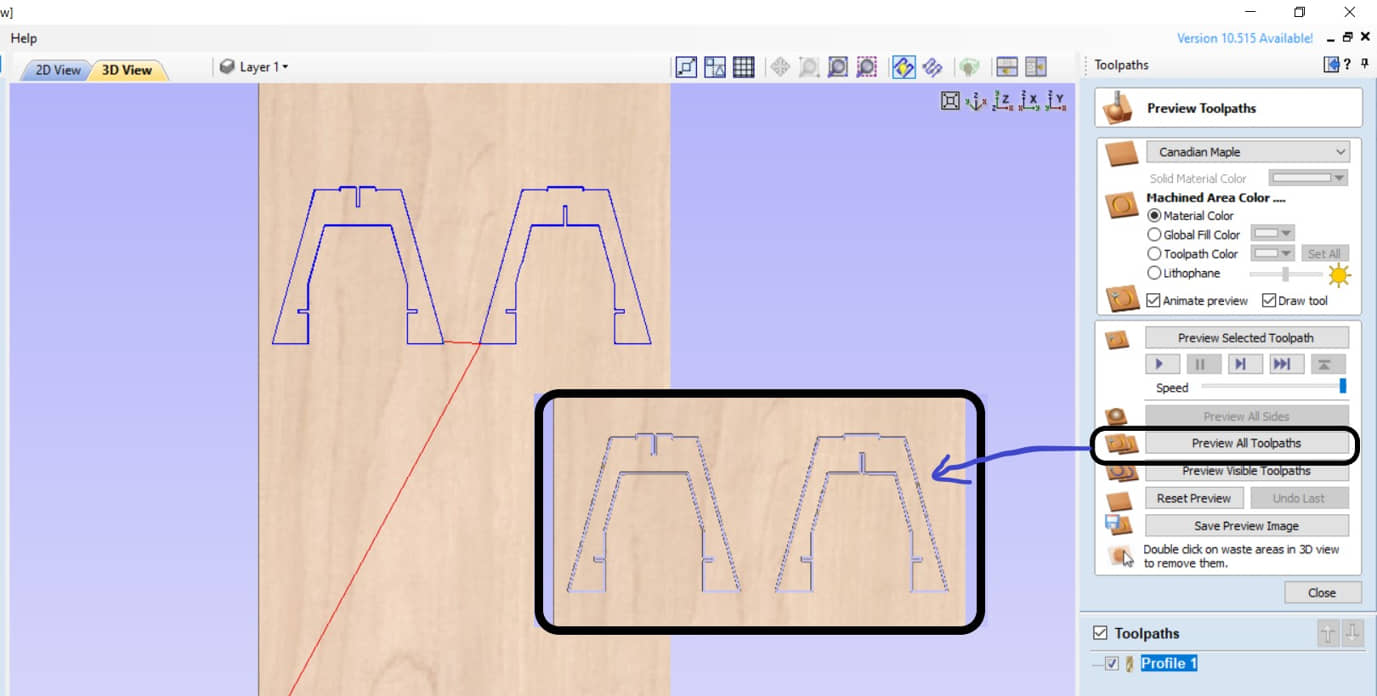
We can see the results of the toolpath in 3D.
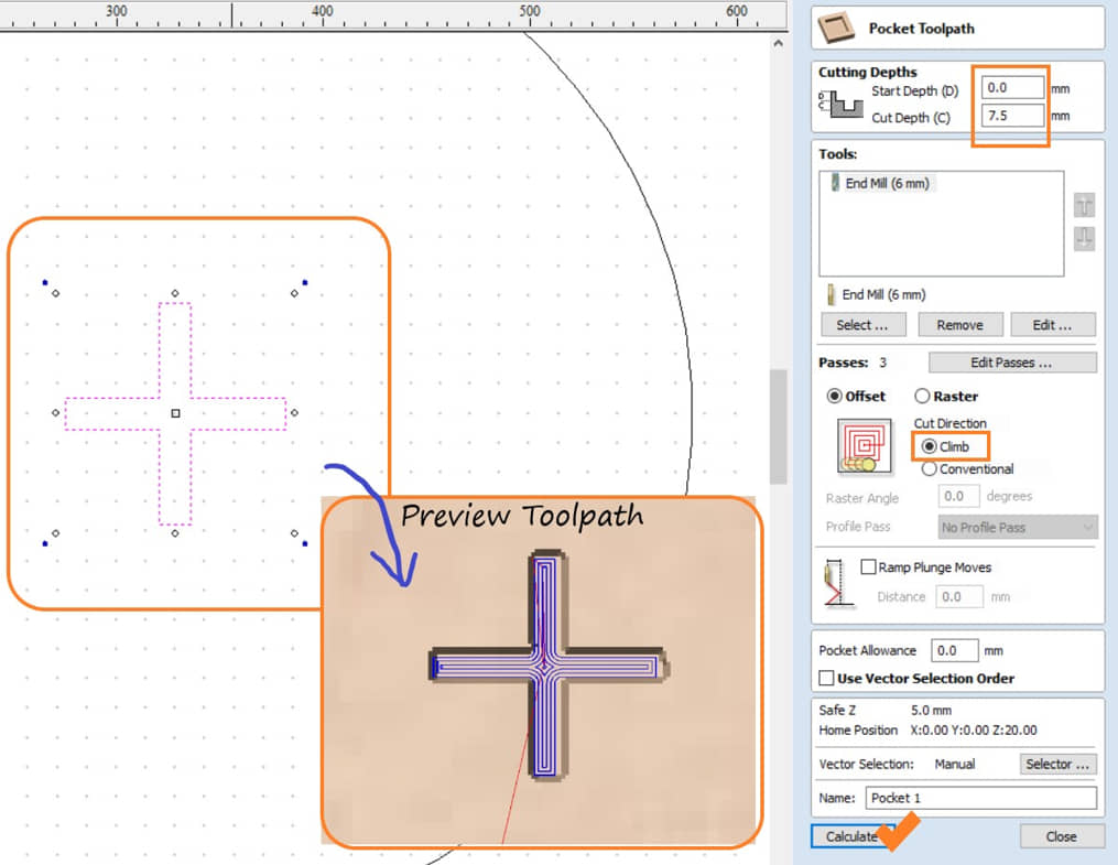
Create the pocket
Pocket toolpath is used to make pockets (deep food) with a certain depth. We can choose the curve that the bag will make, determine the depth, and the method of making whether climb or conventional. Then we can run calculate to create a pocket toolpath.
Generate the G Code & Machine Process
To save the use of materials we can rearrange the position of the curve. We also need to adjust the position of the curve to be cut with the availability of existing materials. So we need to define the re-break tool. Once we have some toolpath definitions, we can do the machining. To run the machining process, we can do it for each toolpath process or we can make one toolpath process into one G-Code program for machining.
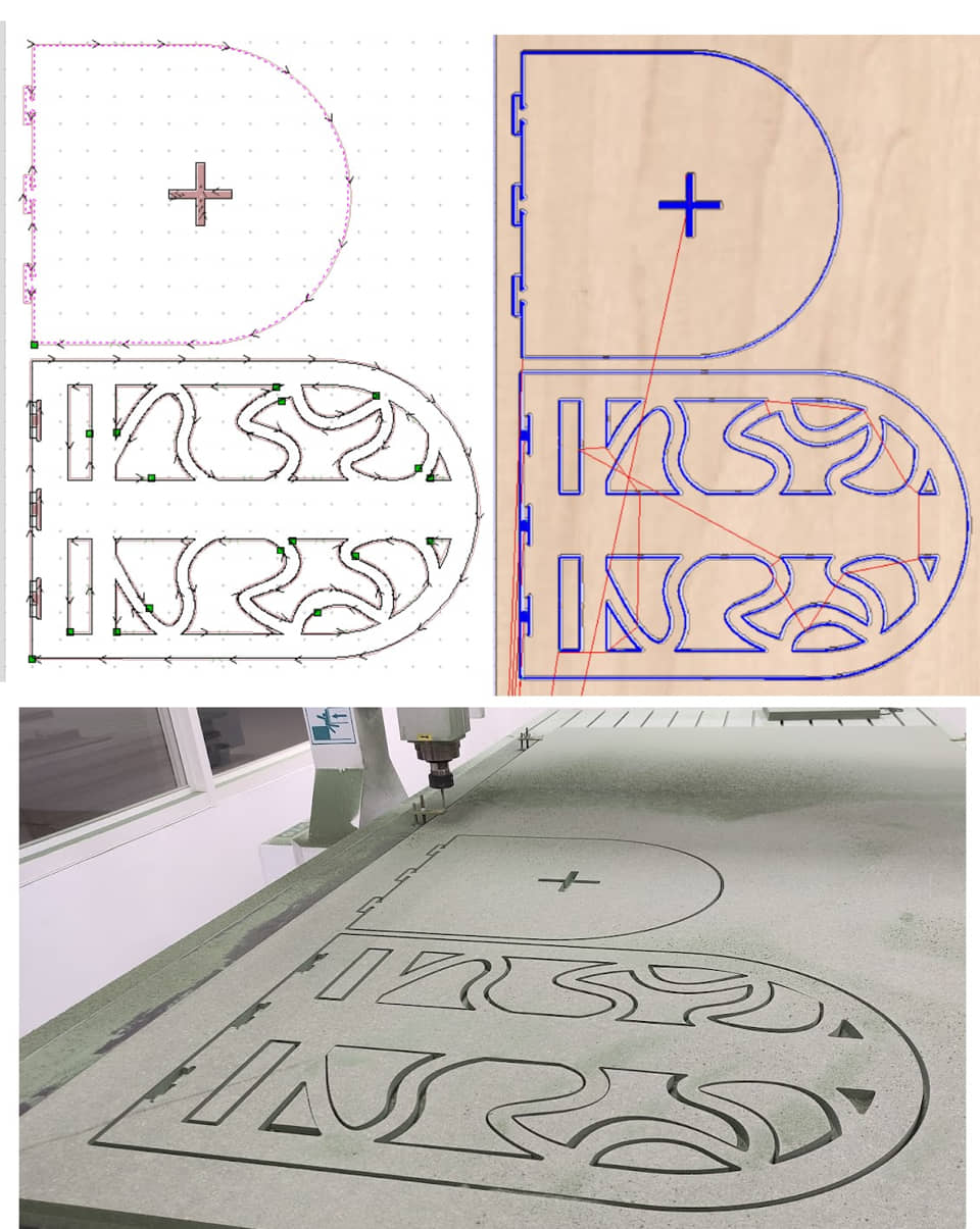
In my assignment I will make in two machining processes, namely : the leg group (3 parts) and the chair back group (2 parts).
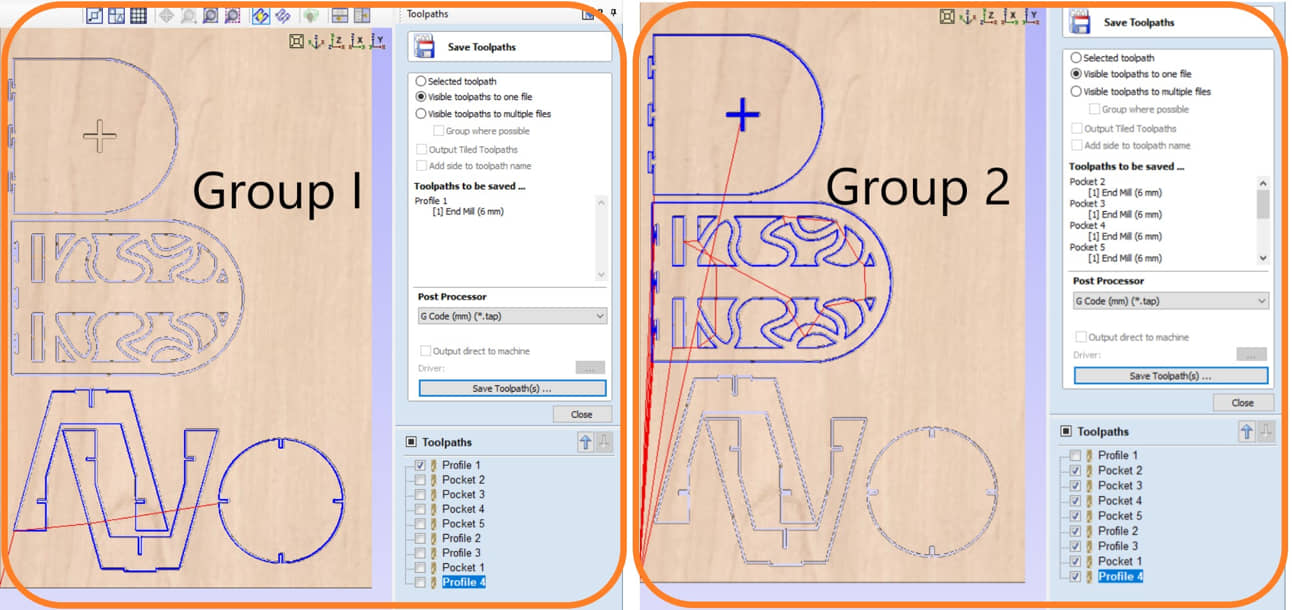
Info
In practice I still have to rearrange the position of the curve because it has to adjust to the availability of materials.
and this is the results :
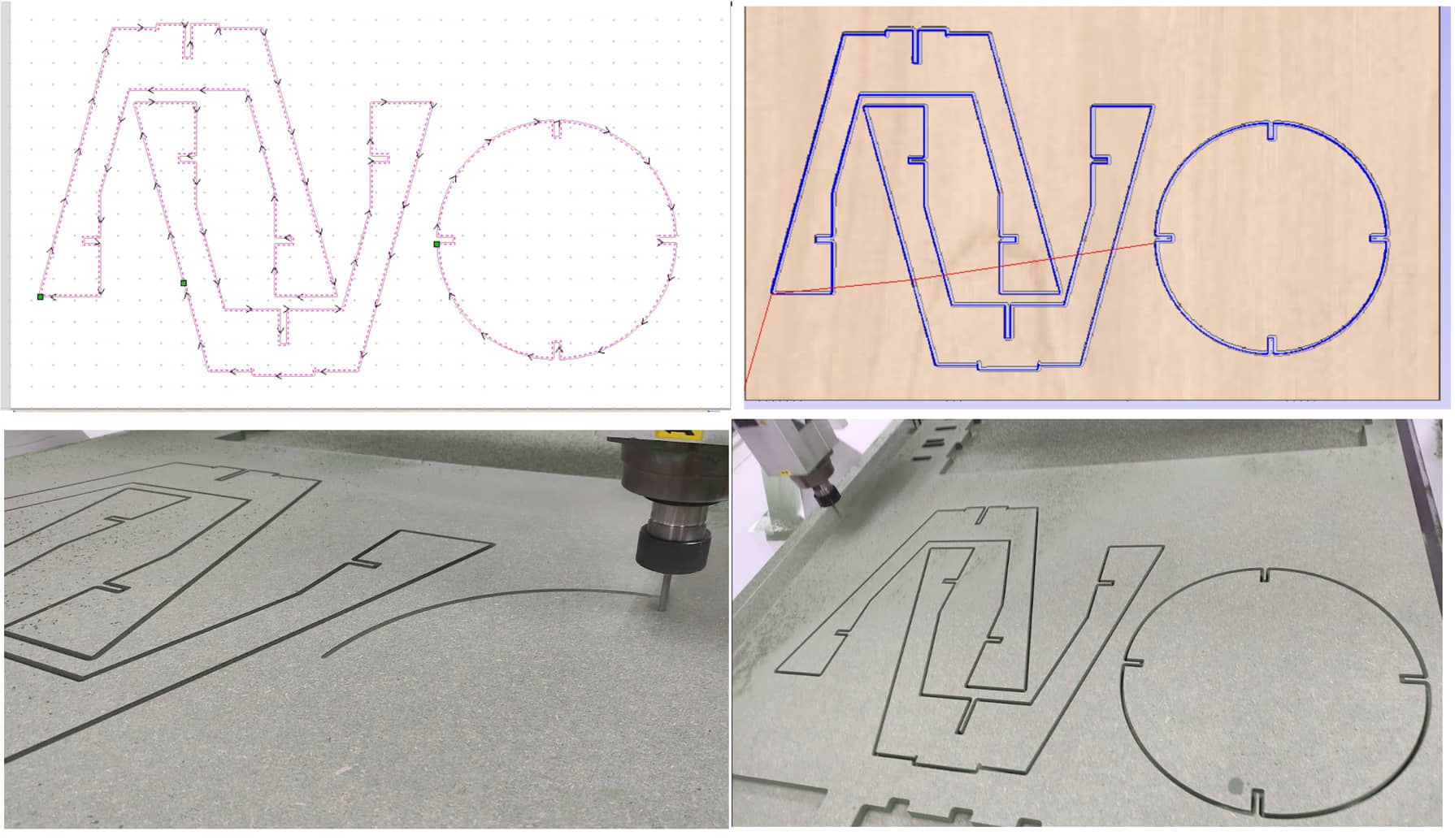
The result of the toolpath is in the form of G-Code which we can see as follows :
T1M6                     //change tool to tool number 1
G17                      //Plane selection to X-Y plane
G0Z20.000                //Move (rapid) the tool without cutting to Z coordinate
G0X0.000Y0.000S18000M3   //Move (rapid) to origin X/Y and rotate spindle with 18000 rpm
G0X81.173Y321.096Z5.000  //Move (rapid) to start point with Z5
G1Z-3.000F60.0           //Move (cutting vertical) depth Z-3, with feed 60 mm/min
G1X81.039Y321.099F600.0  //Move (cutting horizontal) follow the path, with feed 600 mm/min
X80.902Y321.108          //Move (cutting horizontal) follow the path coordinate
X80.763Y321.124
X80.623Y321.147
...
...
...
X732.225Y393.289
X732.215Y393.430
X732.210Y393.569
X732.212Y393.705
G0Z5.000                //Move (rapid) to raise the tool to Z5
G0Z20.000               //Move (rapid) to raise the tool to Z20
G0X0.000Y0.000          //Move (rapid) to origin coordinate
M30                     //Program end
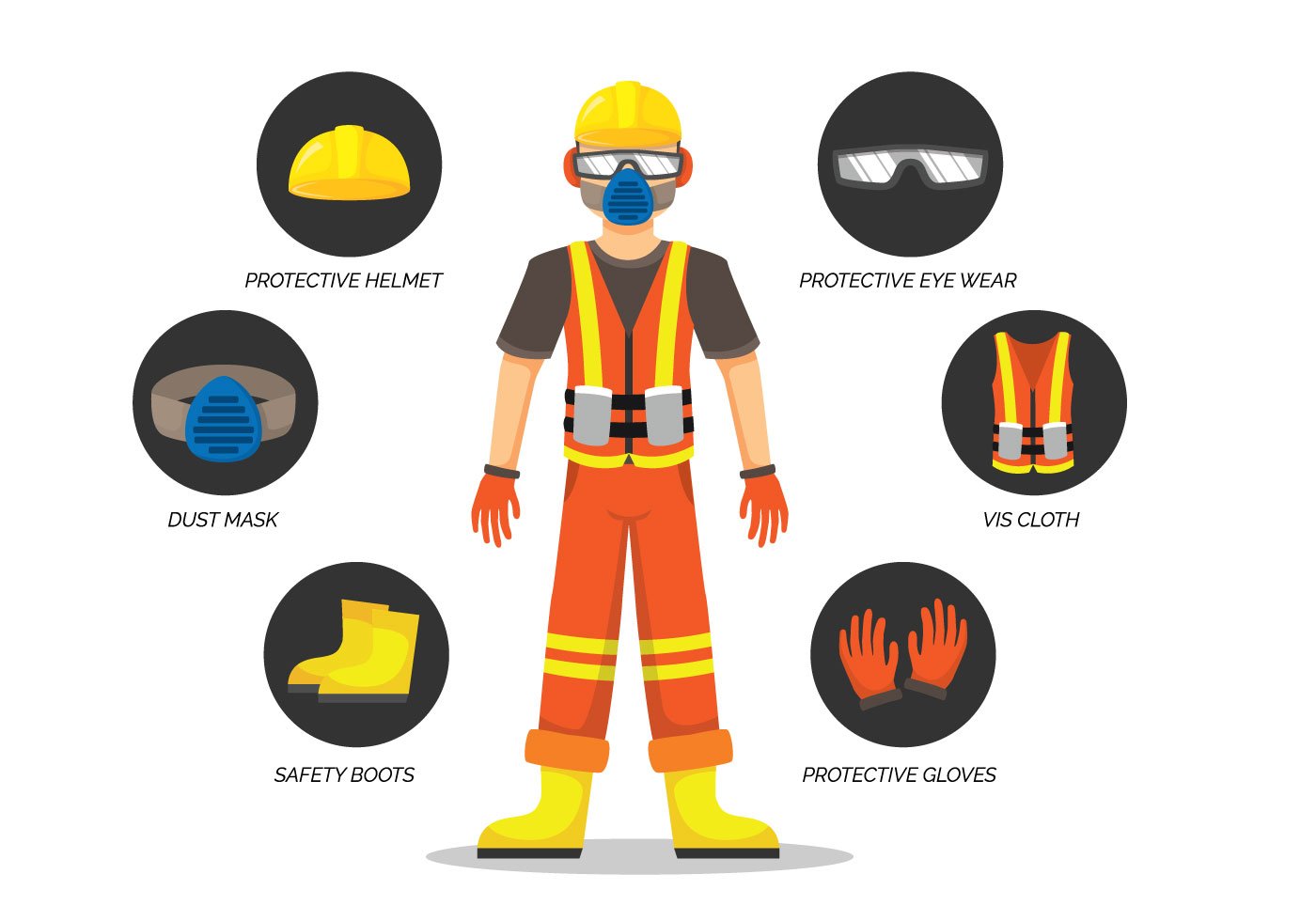
Setting & Preparing for Machine
It is very important to prepare the machine for cutting. This machine is very large and has great power too, so ensuring that the machine works properly by following safety rules is something that must be done. Very easy for accidents so safety first!
Warning
- Safety first is safety always
- Safety doesn’t happen by accident
- Safety isn’t expensive, it’s priceless.
Zhongke ZK-1325
The machine specifications:
- Working Area : 1300mm x 2500mm x 200mm
- Table material : Thicken welded steel Bed, Aluminium Alloy table
- Maximum feed height : 200mm
- X,Y,Z Guideway rails type : Square guide rails Taiwan HIWIN, rack transmission
- Max Engraving Speed : 20000mm/min
- Resolution ratio : 0.002mm
- Repetition accuracy : ±0.02mm
- Spindle power : 3.5KW air cooling spindle or 3.2KW water cooling spindle
- Spindle Rotating Speed : 6000 -18,000rpm(6000-24000rpm)
- Spindle cooling : Water Cooling
- Drive motor system : Stepper Motor and Driver
- Engraving Command : G code, u00, mmg, PLT, HPG
- Command language system : English Version, Windows 98/2000/XP Operation System
- Operational Software : Original Type3 Software, ArtCam software or Wentai Software
- Command language system : English Version, Windows 98/2000/XP Operation System
- Software Compatibility : Support CAD/CAM software, PLT format, Corel Draw, Auto CAD
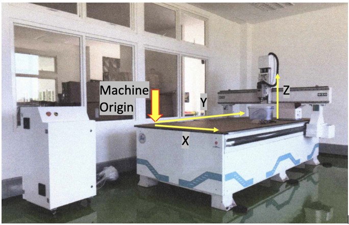
Home Reference Machine
The Home reference machine is a fixed point inside the cnc machine whose values are already stored in the cnc machine. The home position is the default origin point on a CNC, set when the machine is started up. So when we take the cnc machine to the reference point those values automatically get active and the cnc machine comes to know its current axis position. This point is a fixed point on the machine, the position of which is determined by the machine design and manufacturing unit, usually does not allow the user to change.
On this machine, the Home reference machine is located on the left-hand corner (x-y axis) and the z-axis is at the top by pressing HOME.
Origin coordinate position
The origin of the workpiece coordinate system is the workpiece origin, also called the workpiece zero point. Unlike the machine coordinate system, the workpiece coordinate system is artificially set. We can move this position as needed, usually we use it to determine the position of the material with respect to the machine coordinates to ensure the cutting time is exactly at the targeted material position.
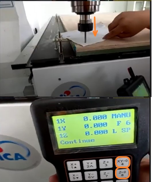
After we install the material on the bed and lock it, we have to set the origin coordinates:
- position the tool on the left x-axis and the y-axis on the bottom side closer to us (inside the material area)
- lower the tool slowly until it approaches the material, place the paper on top of the material, lower it slowly until the paper is pinched and can’t be moved
- press xy->0 and z->0, then the origin coordinates have been determined
- check the coordinates in the handle controller that the coordinates are x=0, y=0, and z=o.
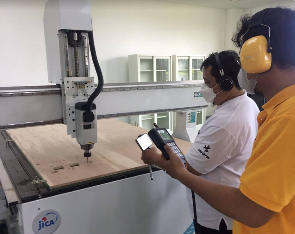
Copying Files and Run the Program
To run the toolpath program produced by Cut2D Pro, we can copy files to a flasdisk (.tap; .nc) and copy them to a handheld or can be run directly from a flasdisk. Position the tool height above the datum approximately 10cm. We press RUN and continue until the engine operates.
Assembling Parts
After the work is finished, we take the material carefully and we assemble it
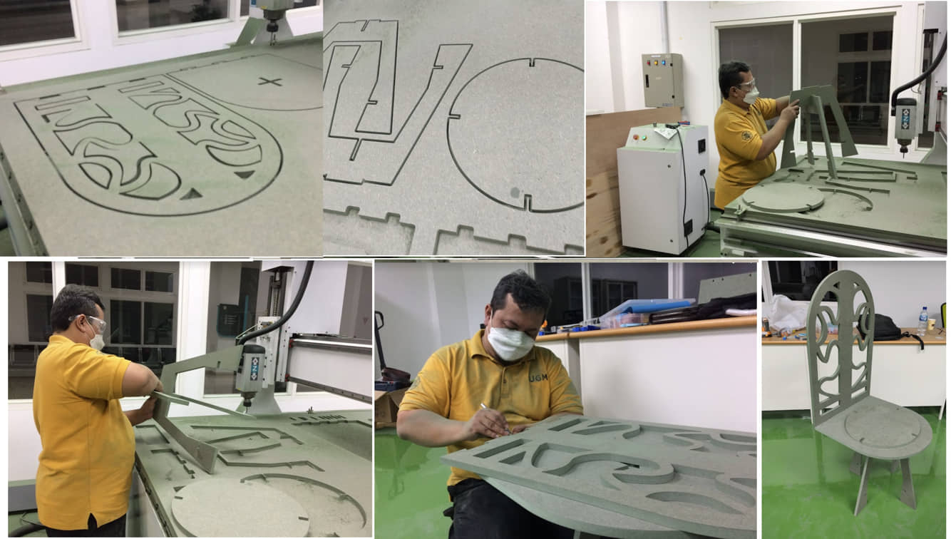
and the HERO SHOT
References
- Kamakura : Computer Controlled Machining: Local Session
- Feeds and Speeds: The Definitive Guide
- Router Bit Basics
- 50 Downloadable Digital Joints For Woodworking
- Fusion 360 CAM + Shopbot 1
- Prepare a Fusion 360 File for Laser Cutter
- More elegant CNC dogbones
Documentation Files
Lessons learned (week 7 : Electronics design):
- Understand how big CNC milling work, characteristic and parameter was used
- Understanding safety to run the big CNC milling
- Understanding and applying the design for cnc milling
- understanding and applting CNC milling process