11. Output devices
This week I worked on adding an output device to a microcontroller board and program it to do something. [Reference]
Group assignment
This week of group assignment, We try to measure the power consumption of an output device. Click HERE to see more detail of the group assignment.
Individual assignment
Heroshot
Motor
I plan to make a board that can control the motor. Because I assume that the Ball-In game machine will be installing a motor that can produce airflow which can blow the ping-pong into the air.
SAMD11C14A pinout
First, I’ve chekced which pins is suit for to do PWM control.
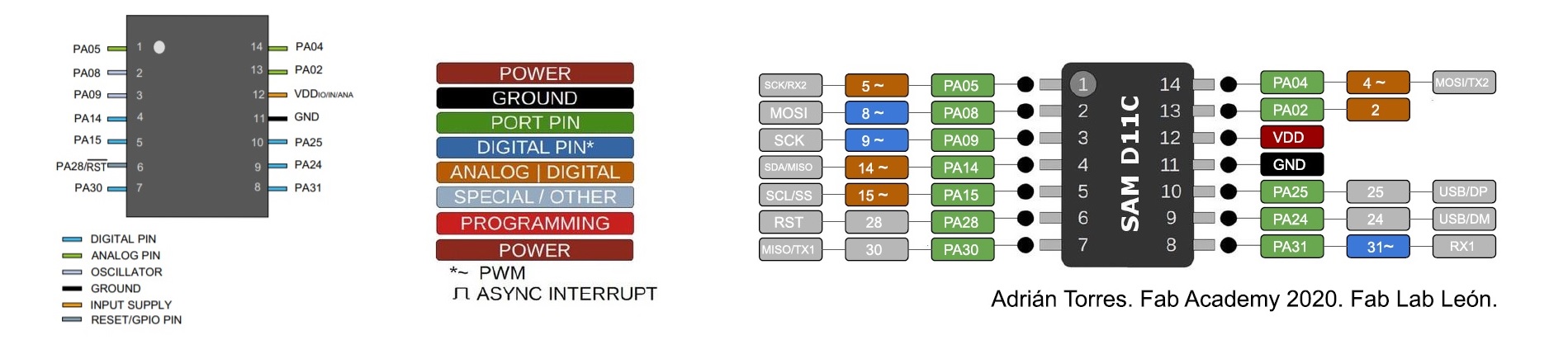
| Type | Pins |
|---|---|
| Digital pins | PA02, PA04, PA05, PA08, PA09, PA14, PA15, PA31 |
| Analog pins | PA02, PA04, PA05, PA14, PA15 |
| PWM | PA04, PA05, PA08, PA09, PA14, PA15, PA31 |
| Source |
Test with hello.servo-D11C
And I found out that there is an board that similar to what I want to do.
German ordered this board before FA2022 started, because he want me to practice my soldering.
Then I tested this board with motor and motor controller to see is that works.
And it works
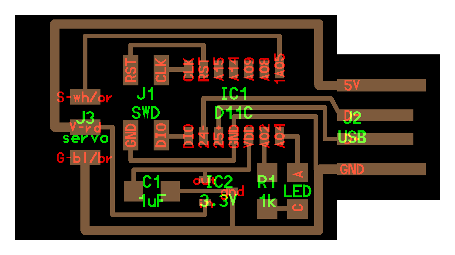
Redesign
So I redesign it on my own.
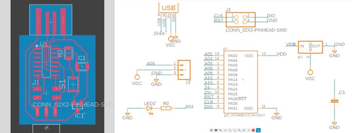
| Type | Component | Quantity |
|---|---|---|
| microcontroller | Atmel SAMD11C14A | 1 |
| capacitor | 1uf | 1 |
| resistor | 1kOhms 1001 | 1 |
| led | LTST-C150CKT | 1 |
| regulator | 3.3V 662K | 1 |
| pin | 2x2 Male Pin Connector | 1 |
| pin | 1x3 Male Pin Connector | 1 |
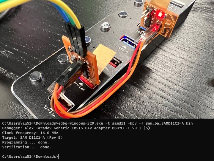
Install bootloader
After milling, I downloaded the edbg and sam_ba_Generic_D11C14A_SAMD11C14A.bin file, then I’ve install the .bin file into the chip by using this command in Windows CMD
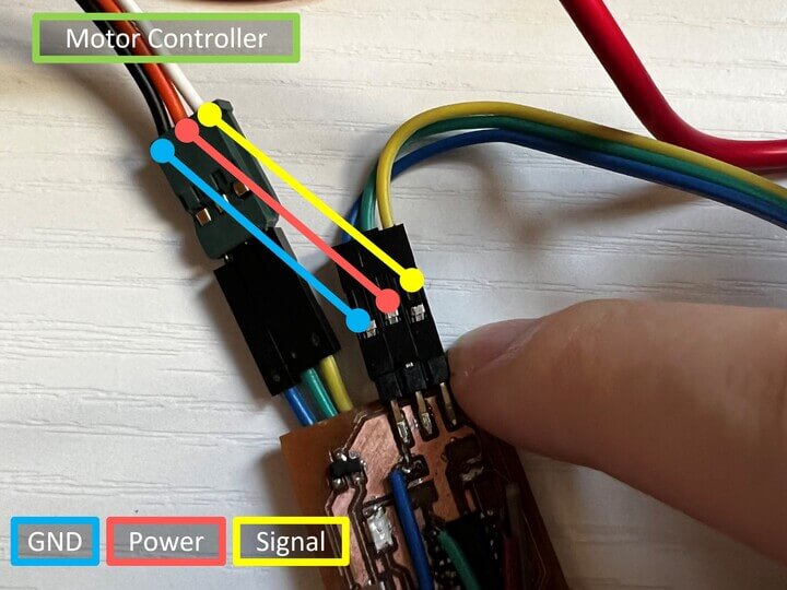
Connecting wires
Motor controller have three wires: Power, Ground, and Signal. In my case, the black wire is Ground, the red wire is Power, and the white wire is Signal. Then make sure that it’s not connect mistakly.
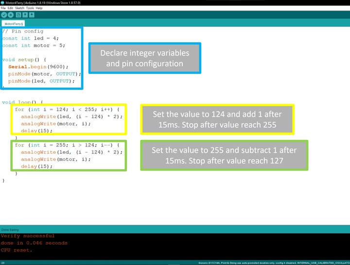
Programming
After making sure there are no short-circuit and wires connect mistakenly. I’ve programmed it with the code below, so the motor will go fast and slow and fast and slow.
Result
And here is the result:
I don’t know why, if I set the value lower than 124, the motor won’t spin. And also it spins slower when the value is higher. Maybe something wrong about the ESC.
I2C LCD Display
Also, there will be a display showing the score and time. So I tried on testing the I2C LCD using my ESP32 board which is the board for final project.
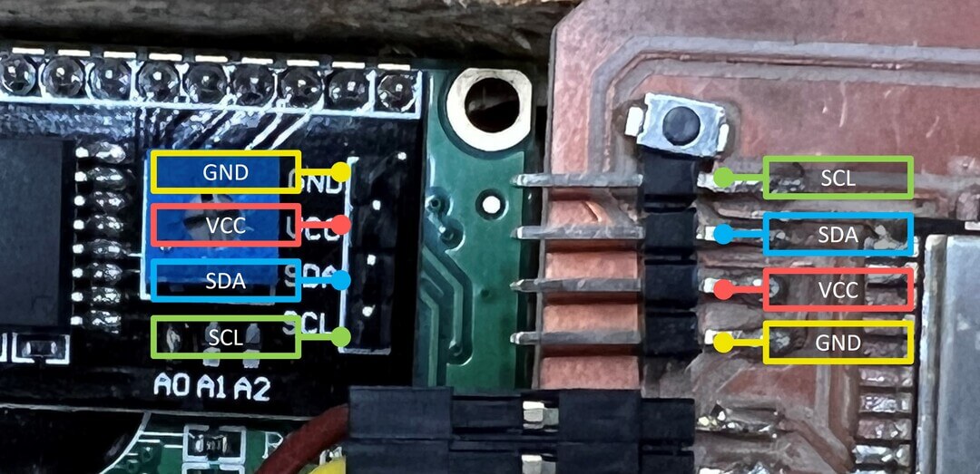
Connecting wires
I2C LCD have four wires: GND(Ground), VCC(5V Power), SDA(Signal), SCL(Signal).
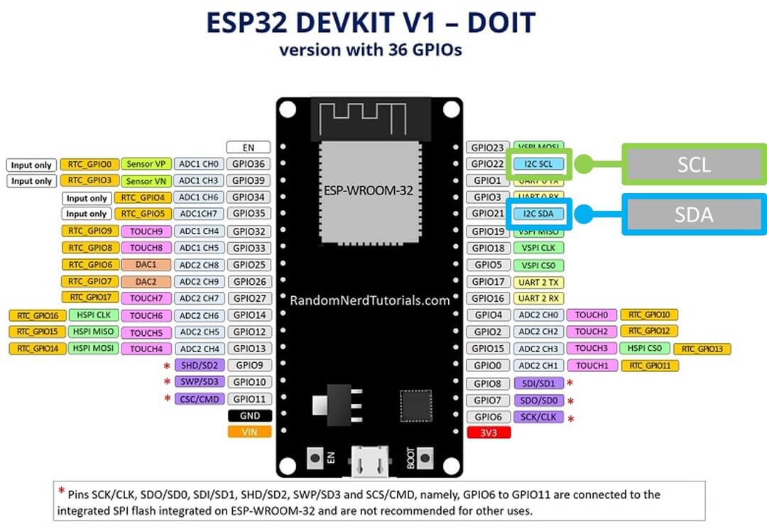
Then I’ve search the pinout of the ESP32
| I2C | ESP32 |
|---|---|
| SDA | GPIO 21 |
| SCL | GPIO 22 |
Programming
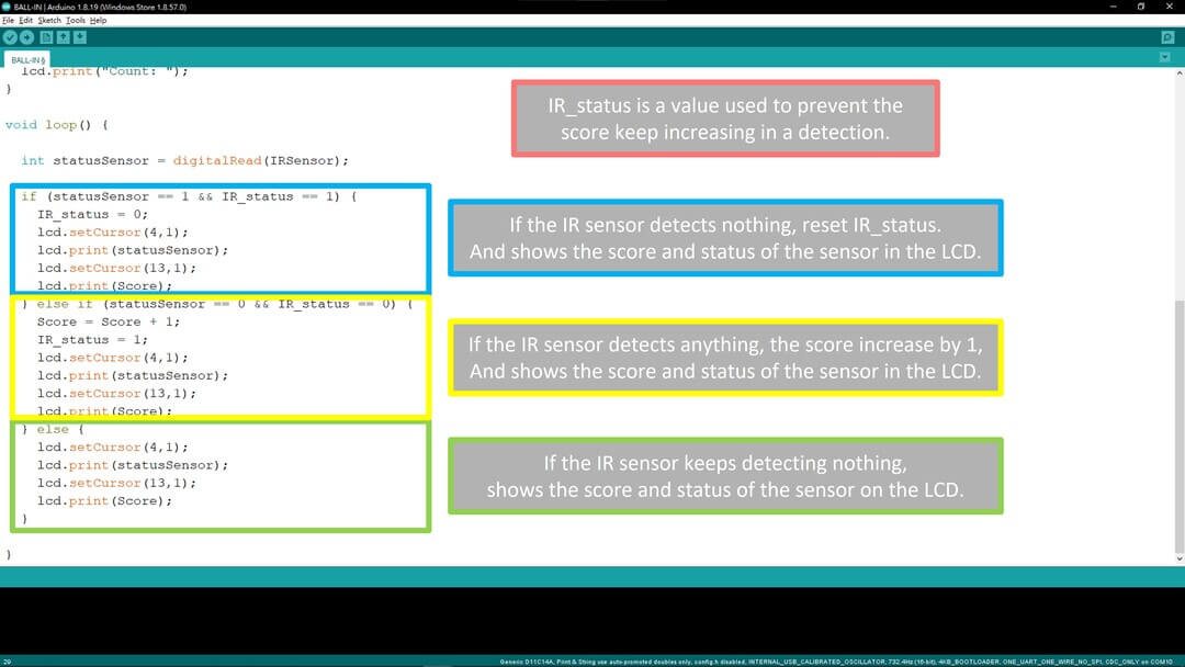
After making sure there are no short-circuit and wires connect mistakenly. I’ve programmed it with the code below, so the I2C LCD will display the status of the IR sensor and the Count of detections.
If the IR sensor detects nothing, reset IR_status, and shows the score and status of the sensor in the LCD.
If the IR sensor detects anything, the score increase by 1, and shows the score and status of the sensor in the LCD.
If the IR sensor keeps detecting nothing, shows the score and status of the sensor on the LCD.
Note: IR_status is a value used to prevent the score keep increasing in a detection.
Result
And here is the result:
Downloads
Motor4Terry PCB board - traces | interior
Latest Motor4Terry code - .ino