Electronics Design & Fabrication
MCU planning
To choose MCU, I need to know what I am looking for.
I’m looking for:
- Support I2C LCD display
- 1 input pin
- 5 output pins (2 PWM)
- Integrated Wi-Fi and Bluetooth (Minor)
MCU selected: ESP32
- ESP32 supports I2C LCD which is SDA and SCL.
| I2C | ESP32 |
|---|---|
| SDA | GPIO 21 |
| SCL | GPIO 22 |
-
ESP32 has 36 GPIO(General Purpose Input/Output) ports, which definitely satisfied my demand.
-
ESP32 has Integrated Wi-Fi and Bluetooth, then I can make a web server or a wireless interface if times are available.
Electronics Design
| Component | Quantity |
|---|---|
| Copper Board 100×150×1.6mm | 1 |
| ESP32 | 1 |
| 1206 Resistors | |
| 1206 3.3V Regulator | 1 |
| 1206 Capacitors | 2 |
| 1206 Switch | 2 |
| Headerpins 1 x 3 | 3 |
| Headerpins 1 x 4 | 2 |
| Headerpins 2 x 3 | 1 |
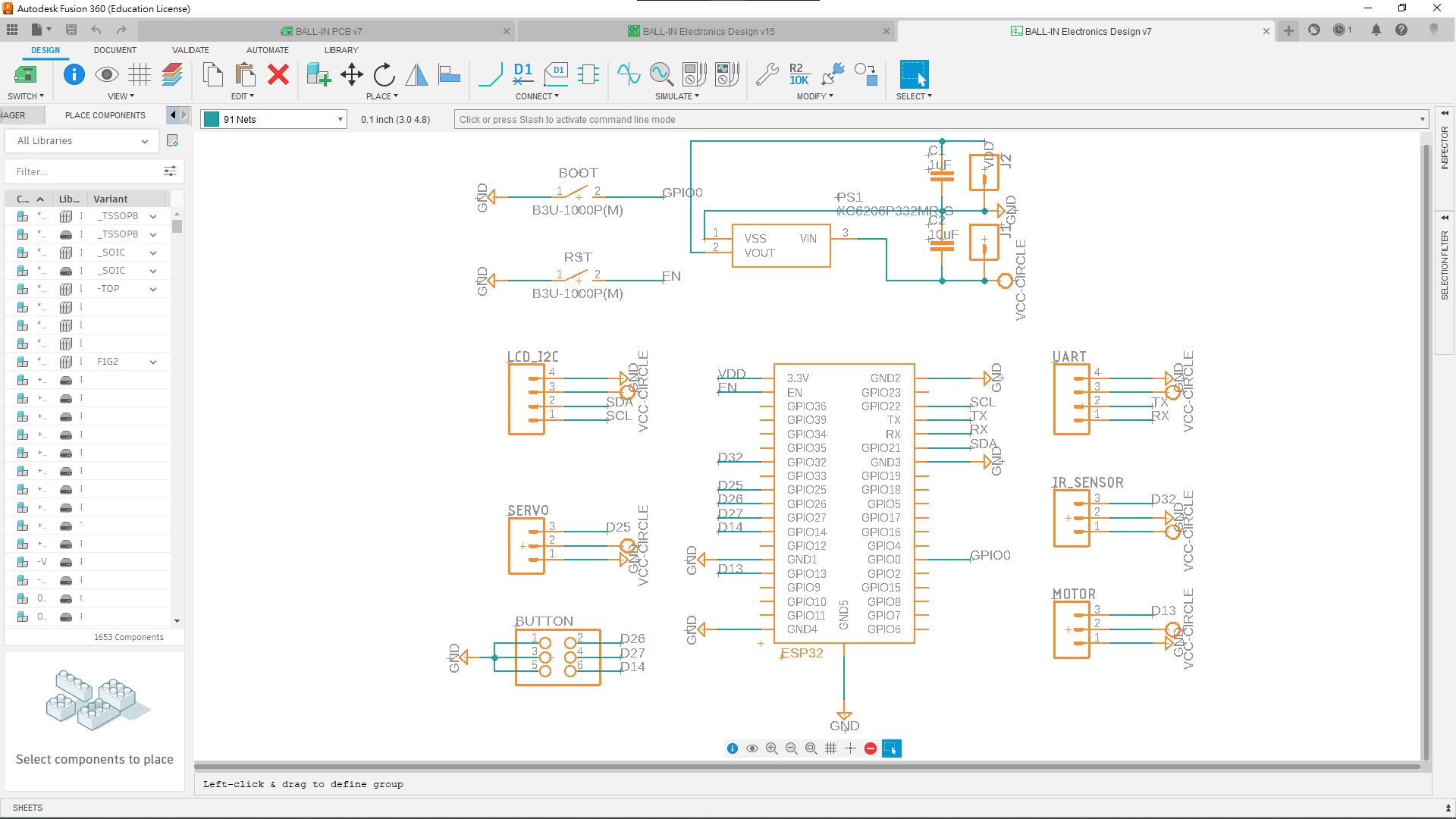
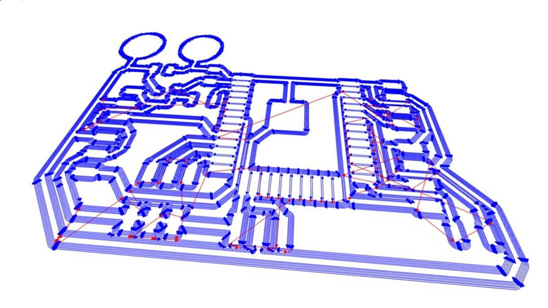
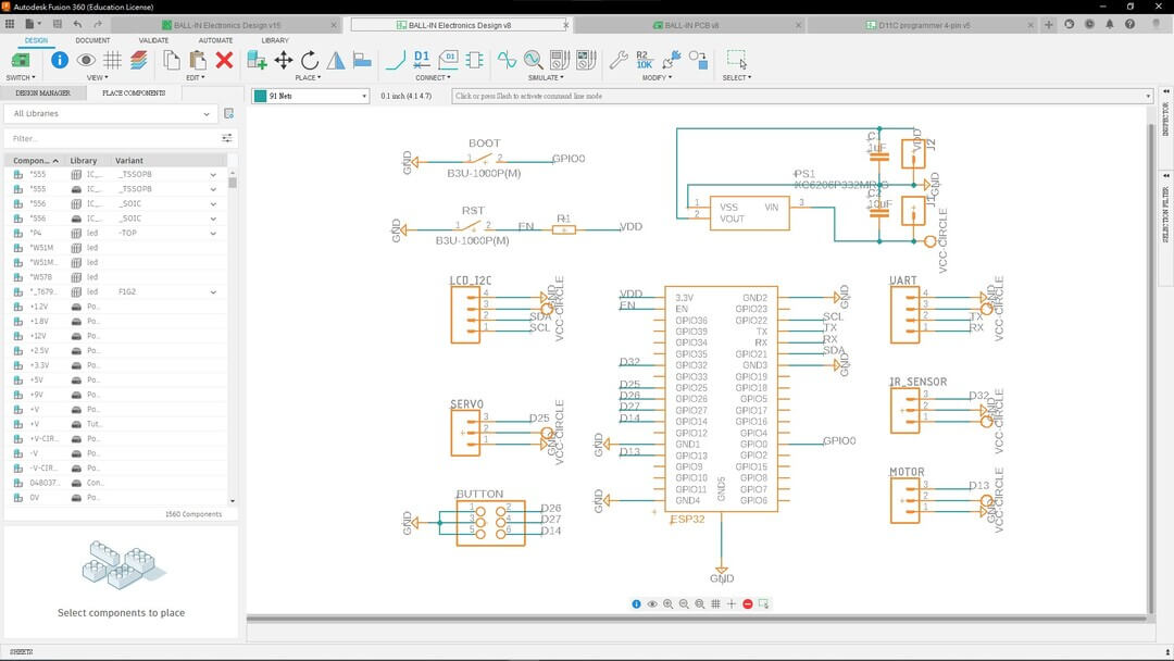
schematic diagram:
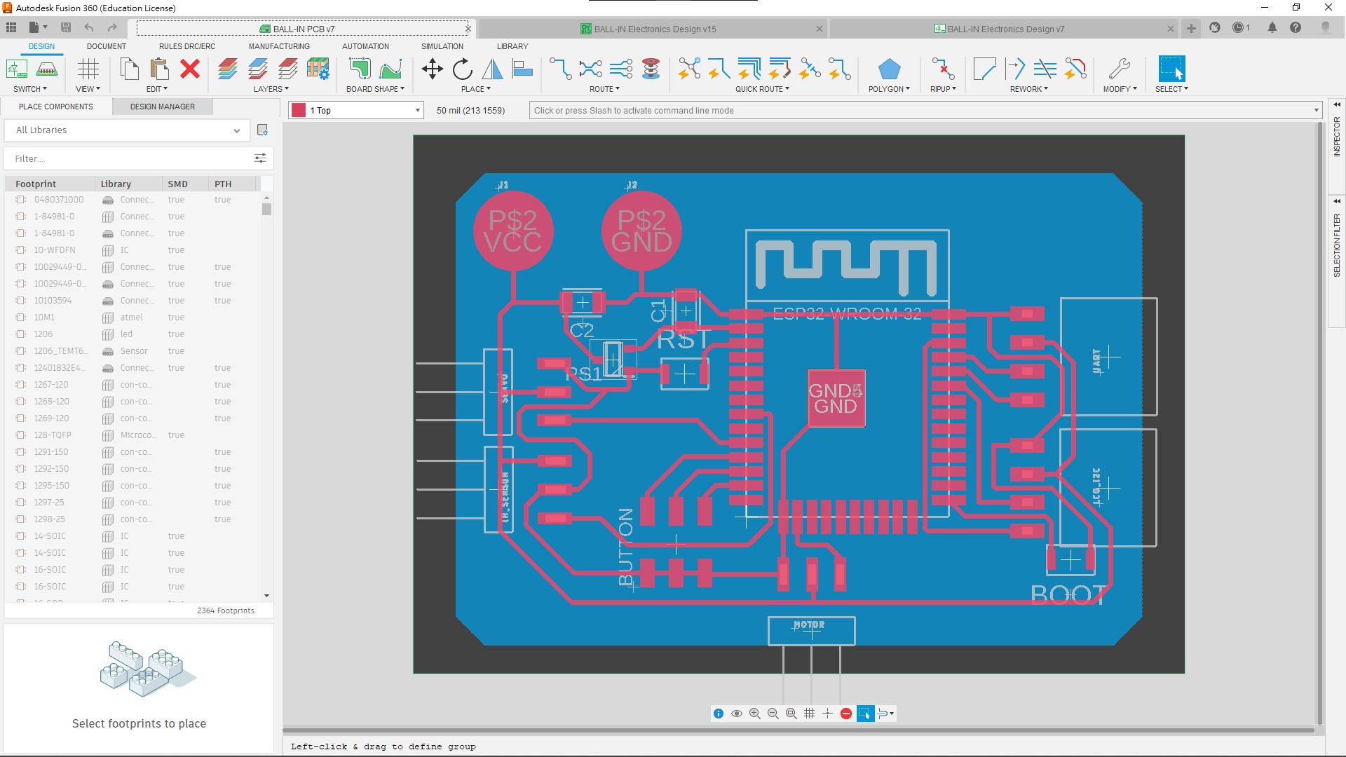
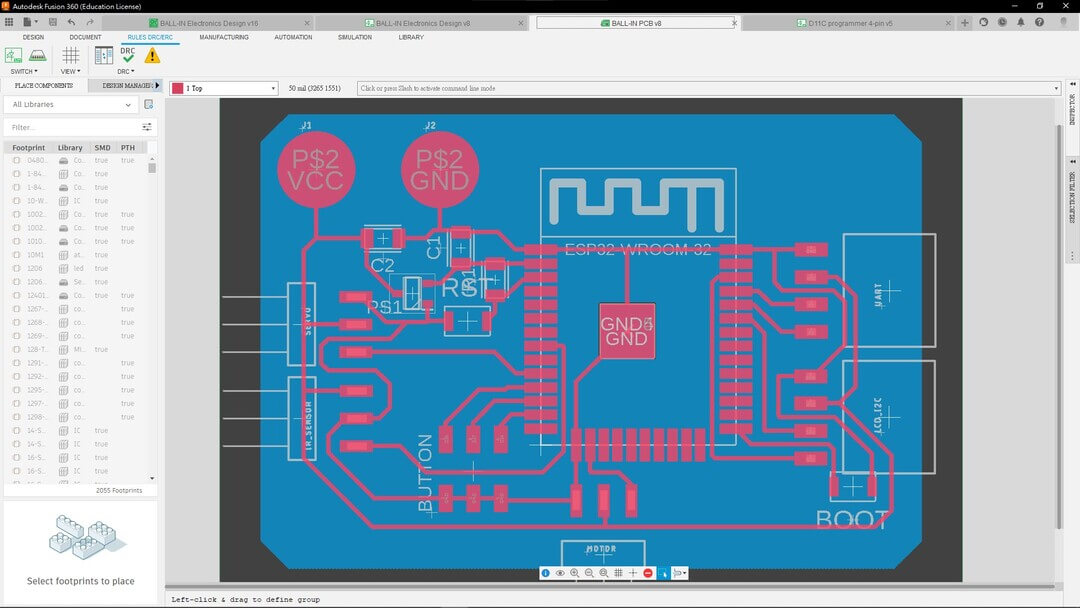
PCB design:
Fabrication
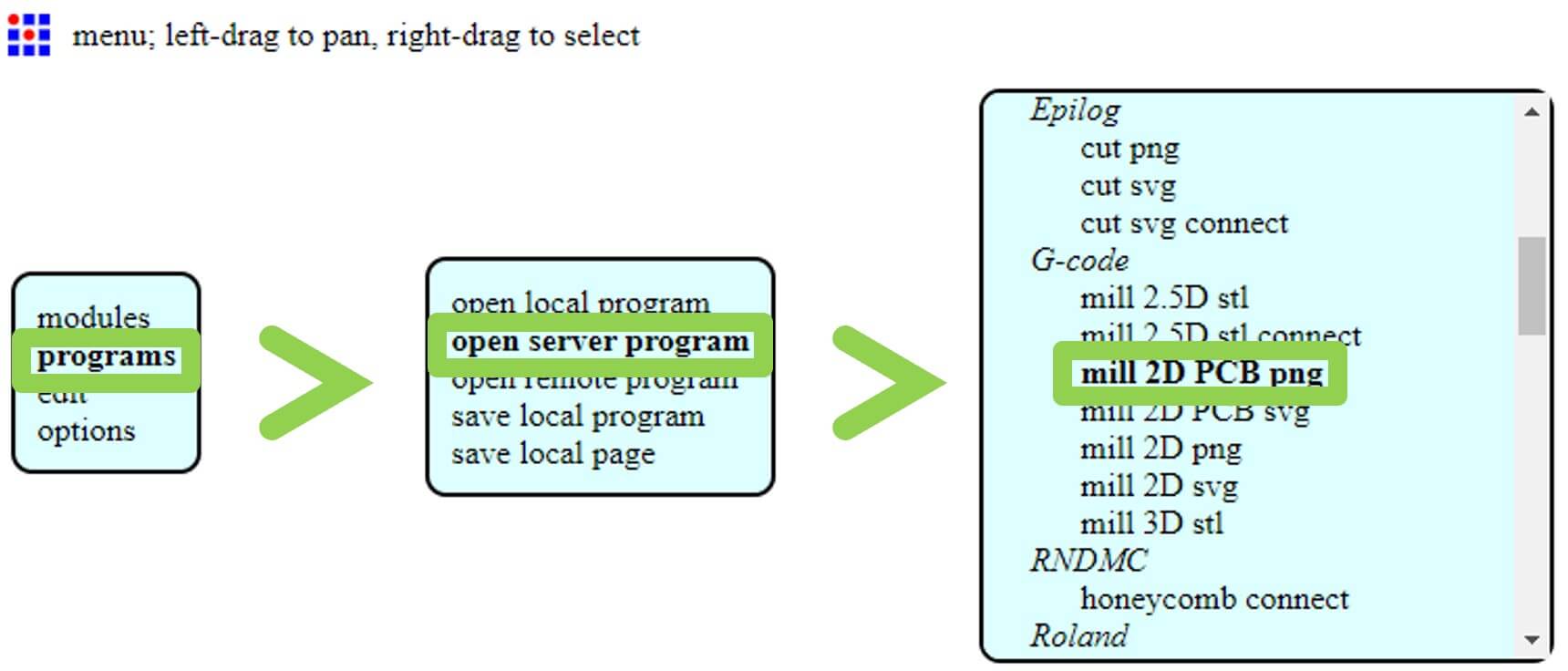
After exporting the traces and interior, I moved on to generate the gcode via mods
Right click > programs > open server program > G-code: mill 2D PCB png
select ‘mill 2D PCB svg’ if you input file type is svg.
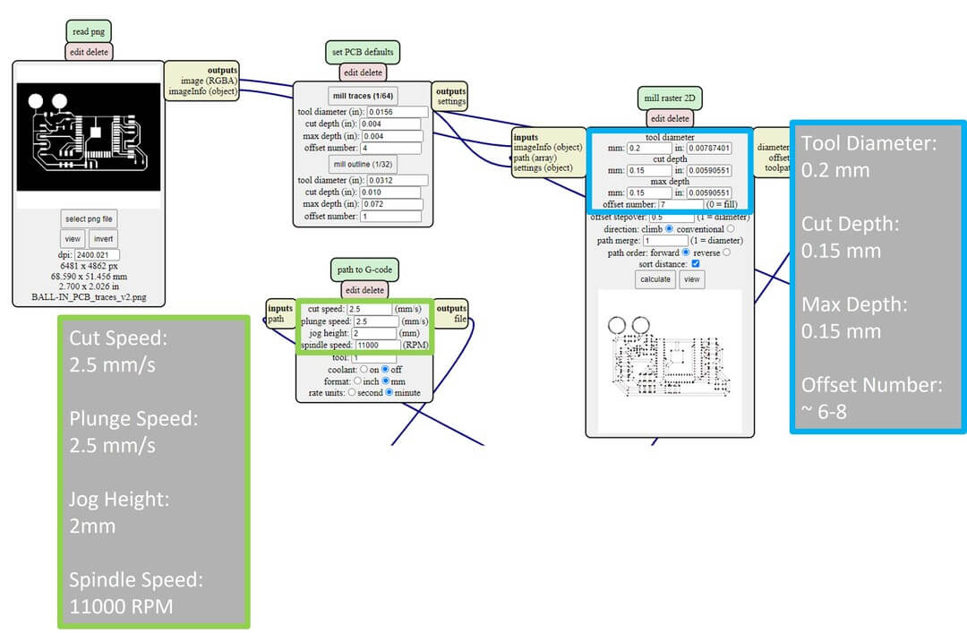
For my milling settings:
| Type | Value |
|---|---|
| Cut Speed | 2.5 mm/s |
| Plunge Speed | 2.5 mm/s |
| Jog Height | 2 mm |
| Spindle Speed | 11000 RPM |
| Tool Diameter | 0.2 mm |
| Cut Depth | 0.15 mm |
| Max Depth | 0.15 mm |
| Offset Number | ~6-8 (For me, 7) |
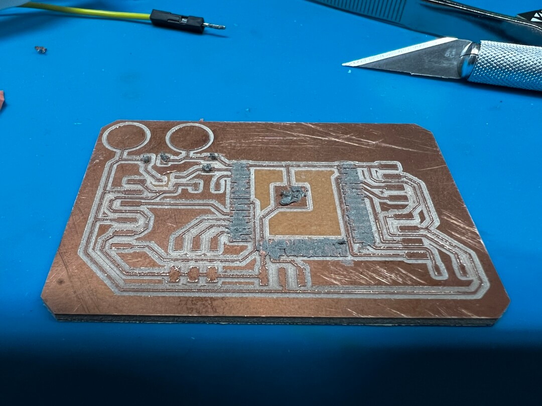
Take a look of the preview, seems no problem.
Looking great! Then clean up the dust using vacuum cleaner.

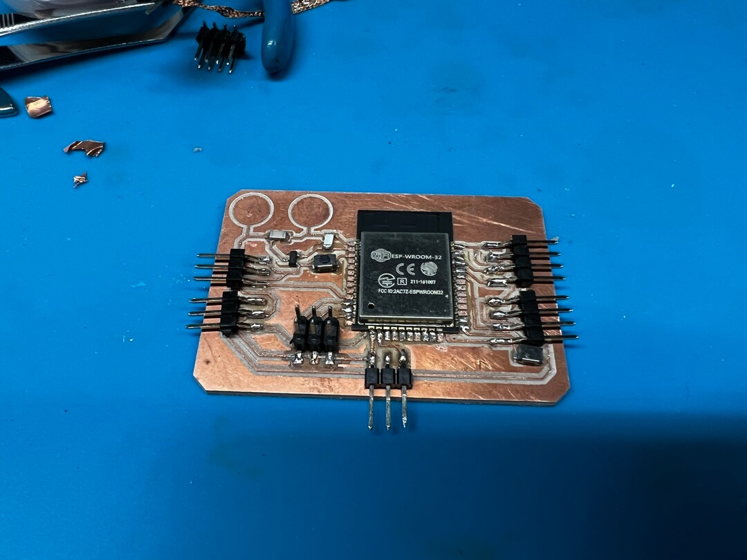
Put on some paste on the soldering spot.
I used a hot plate to assemble all parts.
The reason why I used a hot plate instead of iron is the components are tiny and it’s hard to solder small things in a small board, and it’s easy to touch and melt components by accident.
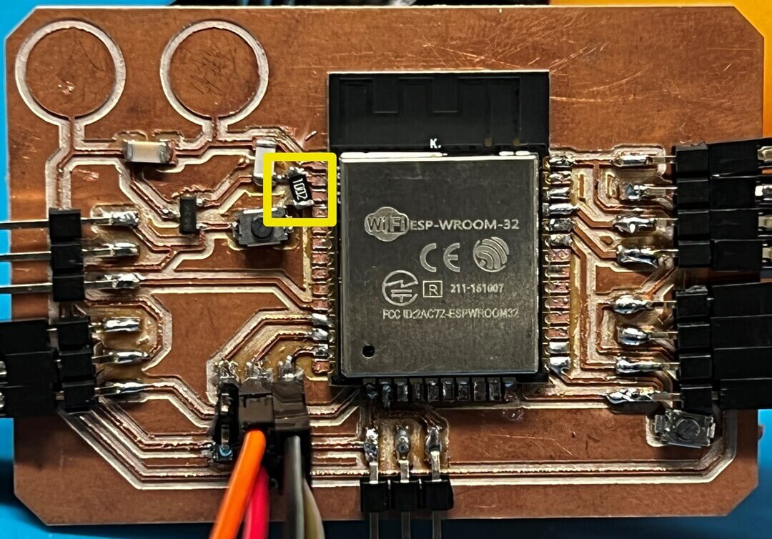
Then, I’ve try to program it to test is the board work or not. It turns out that it can’t be program. I’ve seached the steps of make the ESP32 into the program mode which press the BOOT button for about 5 seconds then keep pressing the BOOT button with RESET button, it usually will go into the program mode. It didn’t works for me…
Then I asked Darren for a help and turns out that the reason why it won’t work is: a 10k resistor is needed to put between EN and VDD. Well…
Then I’ve added the resistor on the existing board, but didn’t mill a new one.
And I also updated the PCB design with the small change mentioned.
Then I connect all devices and do some test with programming, visit next chapter to know more.