Design Development & Planning
First, I need to define what components is needed.
Components
- Wooden Enclosure… CNC, week 8
- Control Stick & Door Handle + Hinges… 3D Print, week 6
- DC motor… To make the ball fly
- Buttons… To select mode, start and stop the game.
- I2C LCD… To select mode, show score and time. Week 11
- IR sensor… To detect the balls, week 13
- Front & panel cover… Laser cutting with acrylic sheet, week 4
Enclosure
Material
For the material of enclosure, I used 18mm OSB for the assignment.

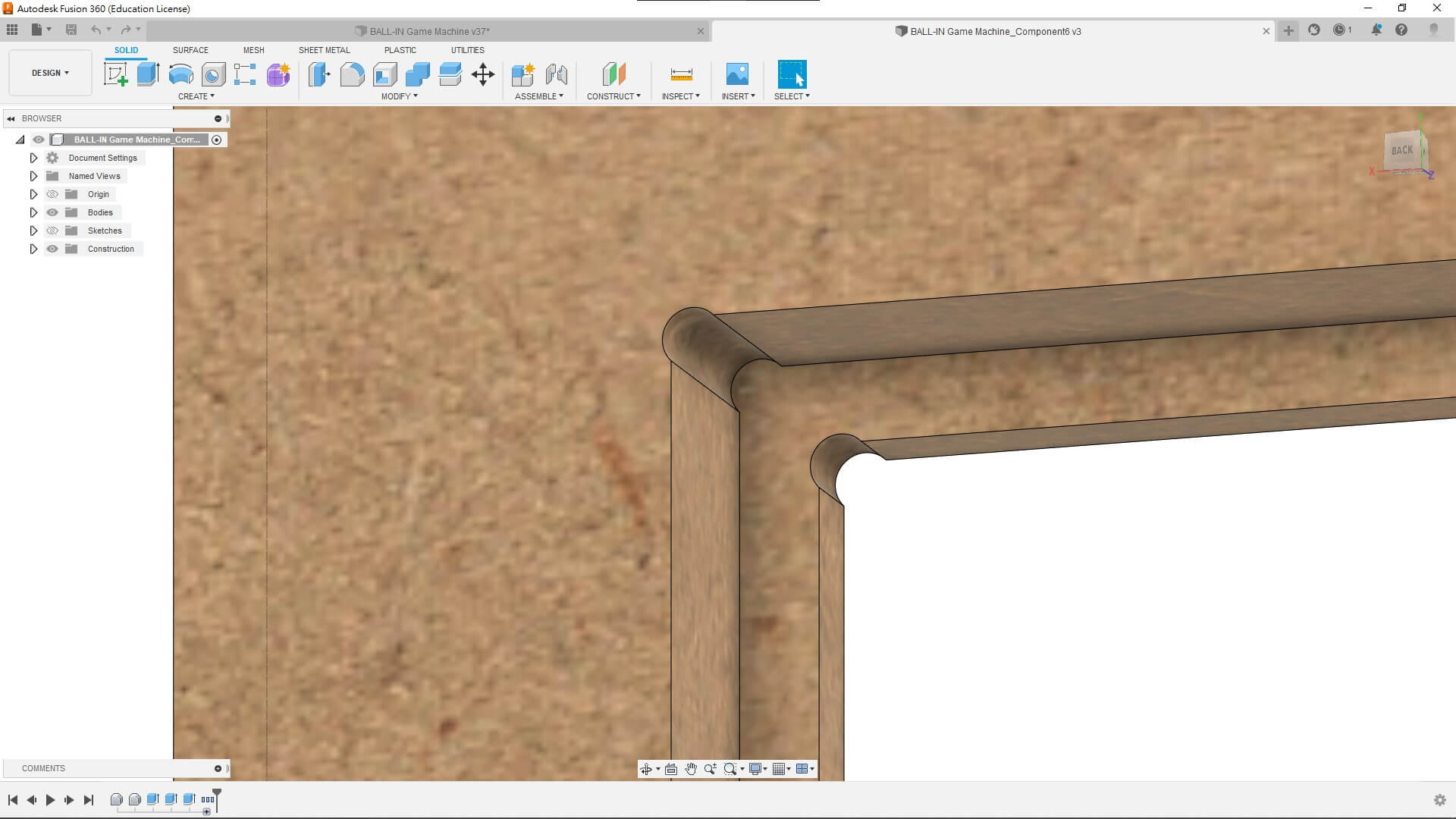
CAD design
I’ve made some features in the model.
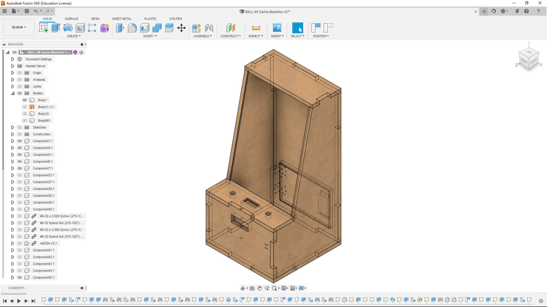
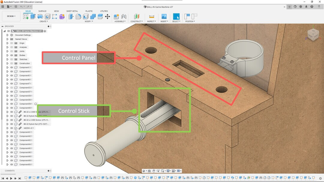
I’ve made the holes for the buttons and the LCD.
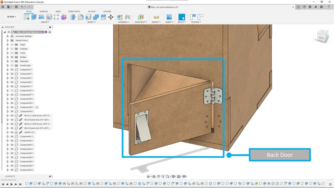
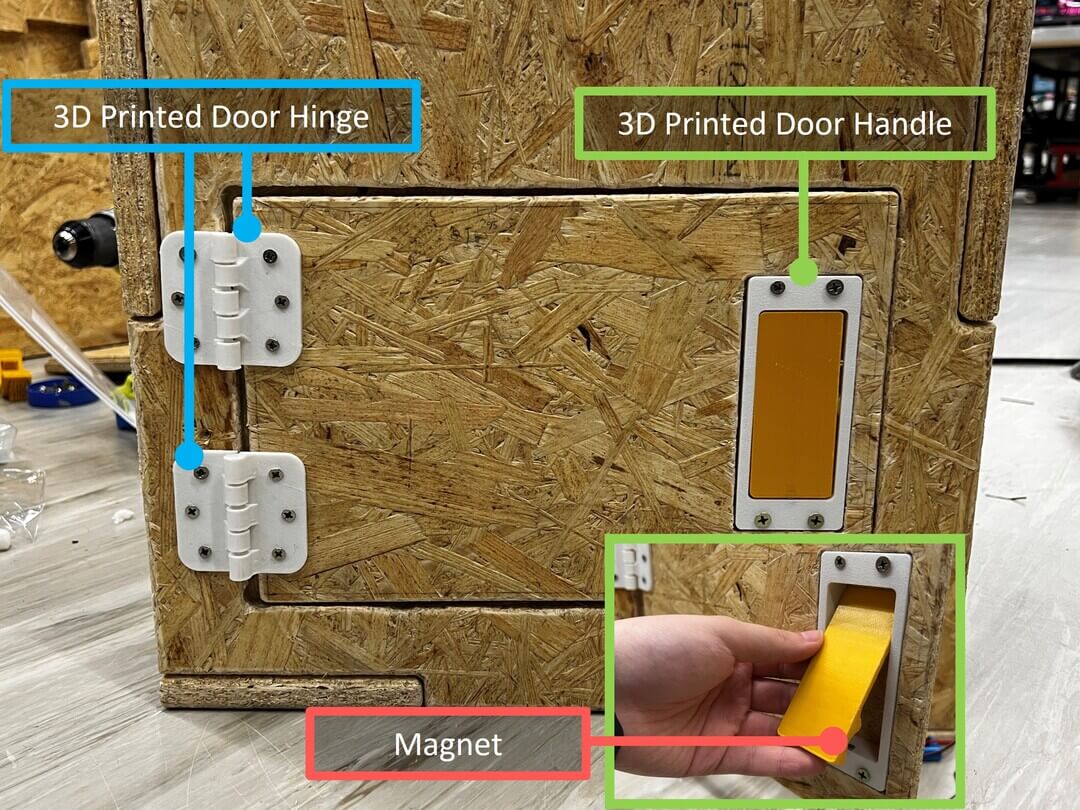
I’ve made the back door for the maintenance and there will be 3D printed door hinges and door handle.
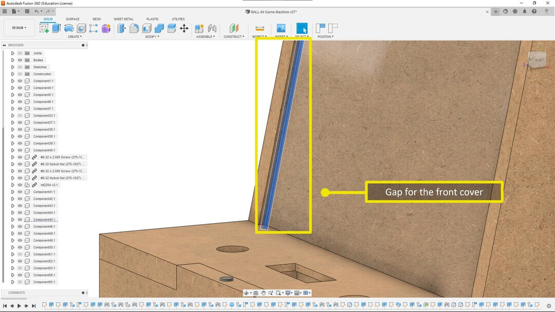
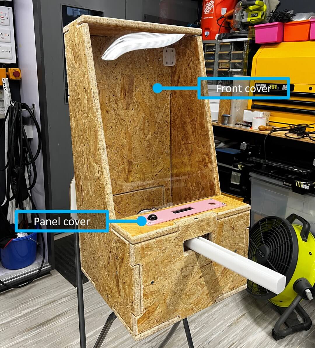
And I’ve also made a gap for putting the front cover.
Before exporting the files, dogbones are needed.
Export the DXF file without kerf.
Then import the DXF into the Easel.
Milling
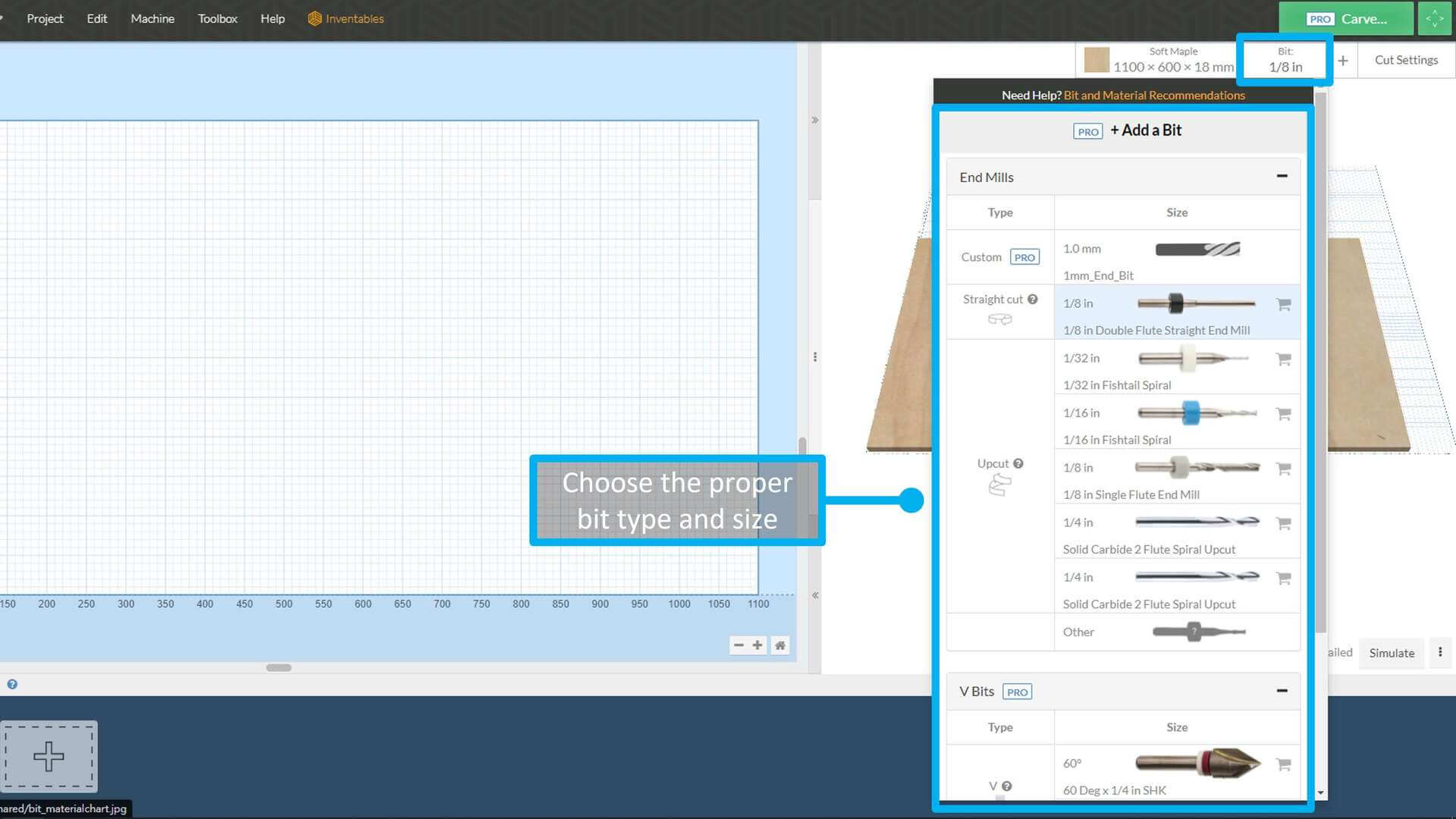
Bit, I’ve choose 1/8 in Double Flute Straight End Mill.
And these value will auto change with the material type.
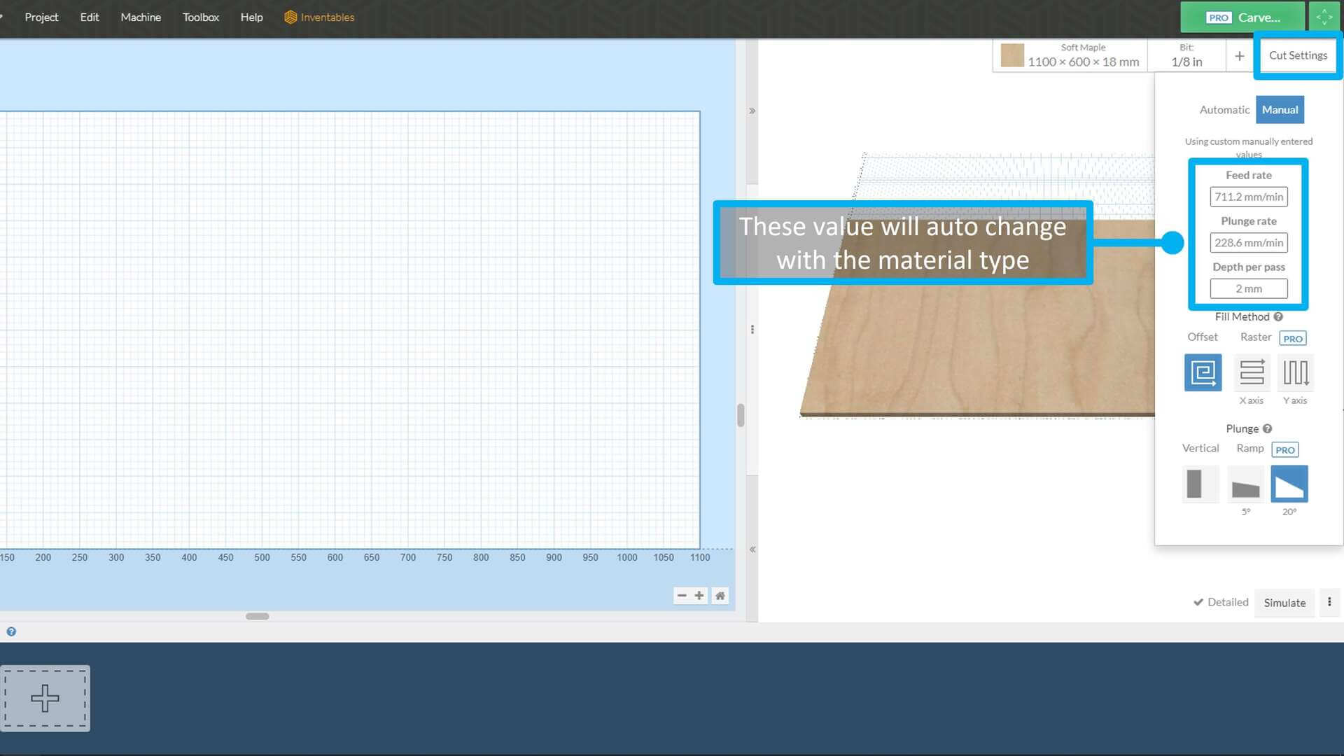
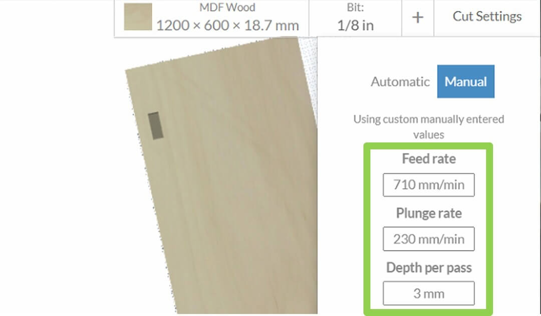
This time, I’ve used:
| Type | Value |
|---|---|
| Feed Rate | 710 mm/min |
| Plunage Rate | 230 mm/min |
| Depth Per Pass | 3 mm |
Then, I’ve import the DXF file into the Easel
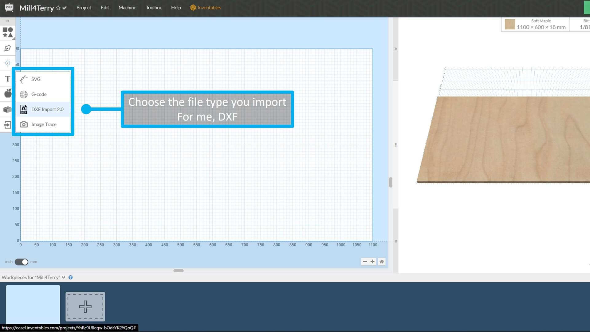
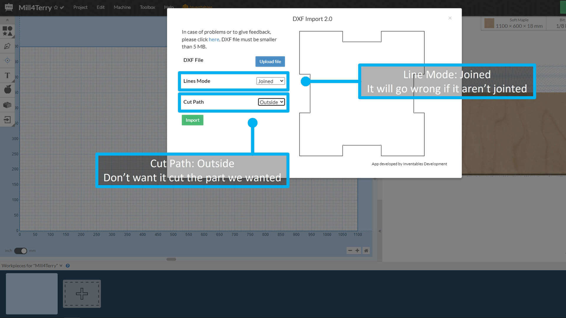
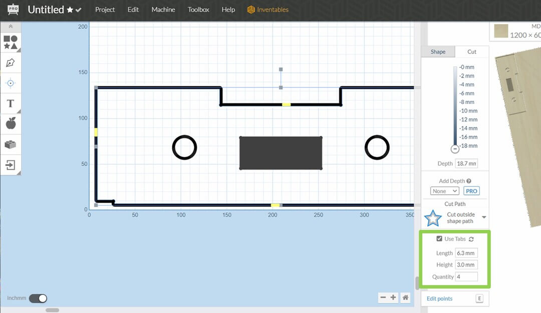
In the confirm box, I’ve set the cut path to outside because I don’t want it cut the part I need. And set joined for the line mode, otherwise it will go wrong.
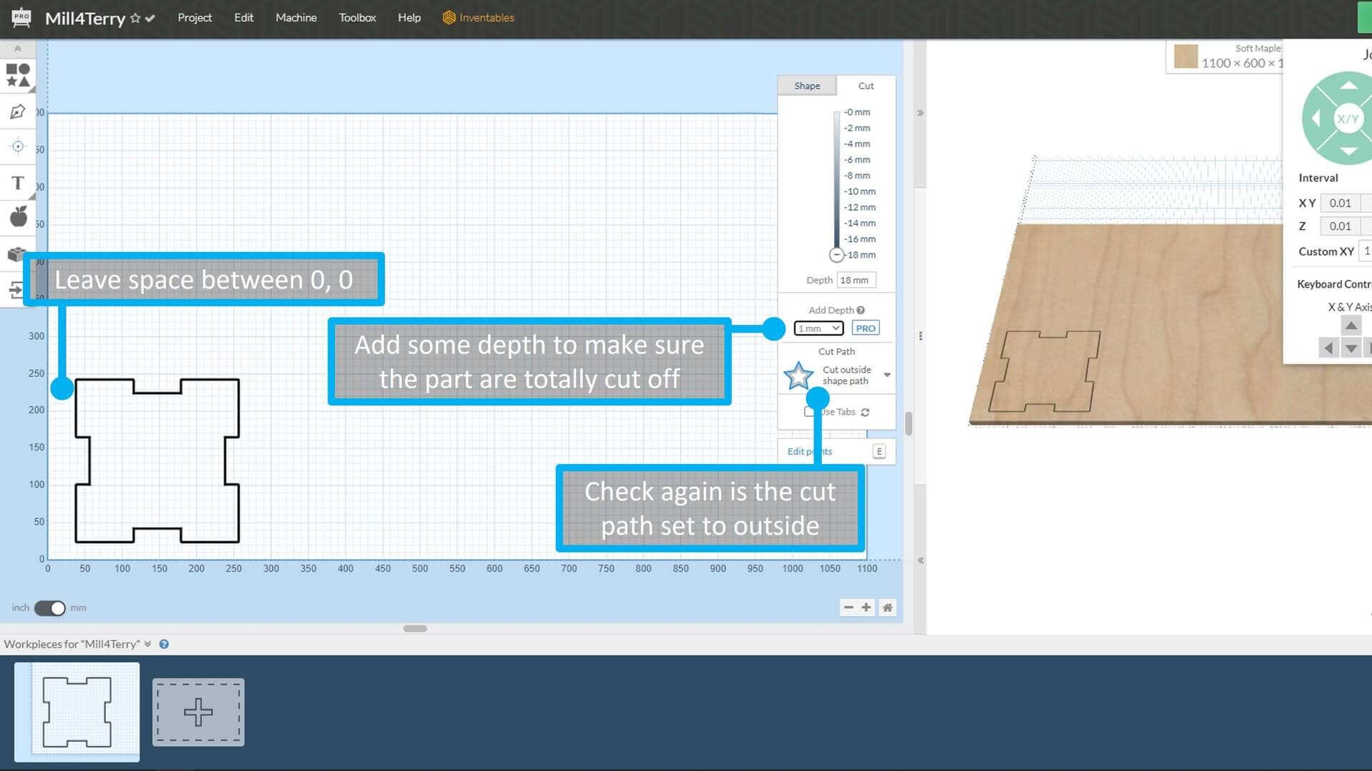
After the DXF imported, I’ve moved it for left some space between the cut path and border.
Then on the left side list, I added 1mm depth to make sure the part are totally cut off.
And check again is the cut path was set to outside.
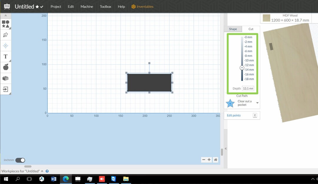
And I’ve some parts that I don’t want it to cut all the way down. So I need to set the cut depth on the object panel.
To avoid the parts moved when it almost done, I’ve used taps. Here’s my settings of the taps:
| Type | Value |
|---|---|
| Length | 6.3 mm |
| Height | 3 mm |
| Quantity | 4-6 |
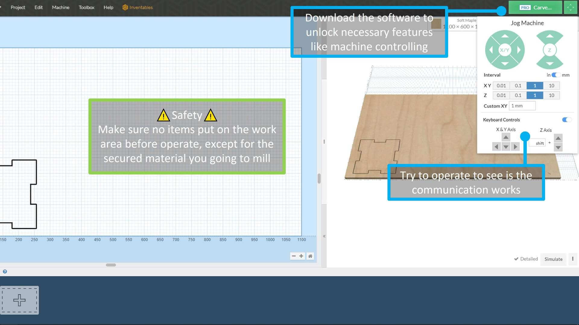
Last few step before milling, I’ve download the software to unlock ‘PRO’, some necessary features like machine controlling.
After that, I’ve tried to operate the machine manually on the ‘Jog Machine’ Panel.
I’ve confirmed the communication works and no items were put on the working area. So let’s move to the milling part.
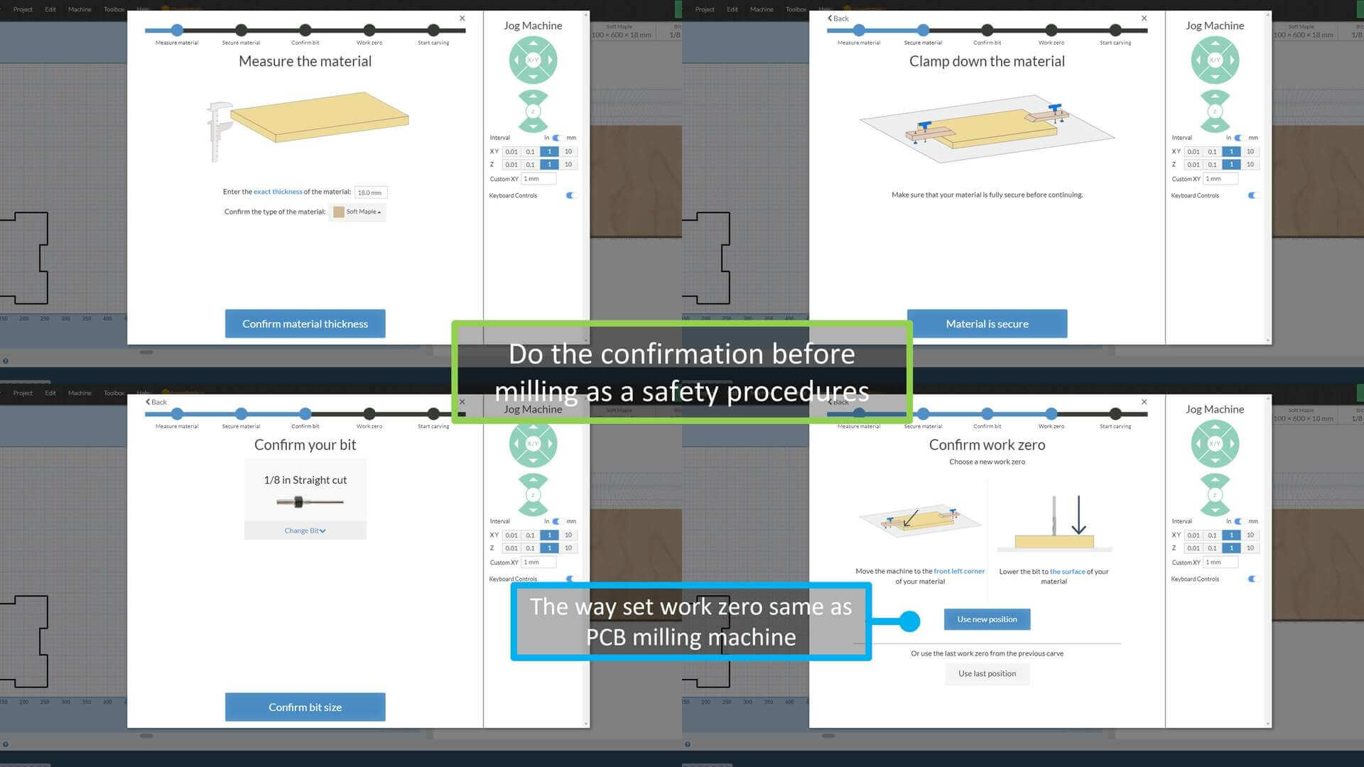
For safety procedures, finish the confirmations before milling.
For confirm the work zero, it’s the same way of setting the PCB milling machine.
After all confirmations, including of making sure the vacuum nozzle is well attached and the button on both vacuum machine and drill were switched on. Then click the ‘Carve!’ to start.
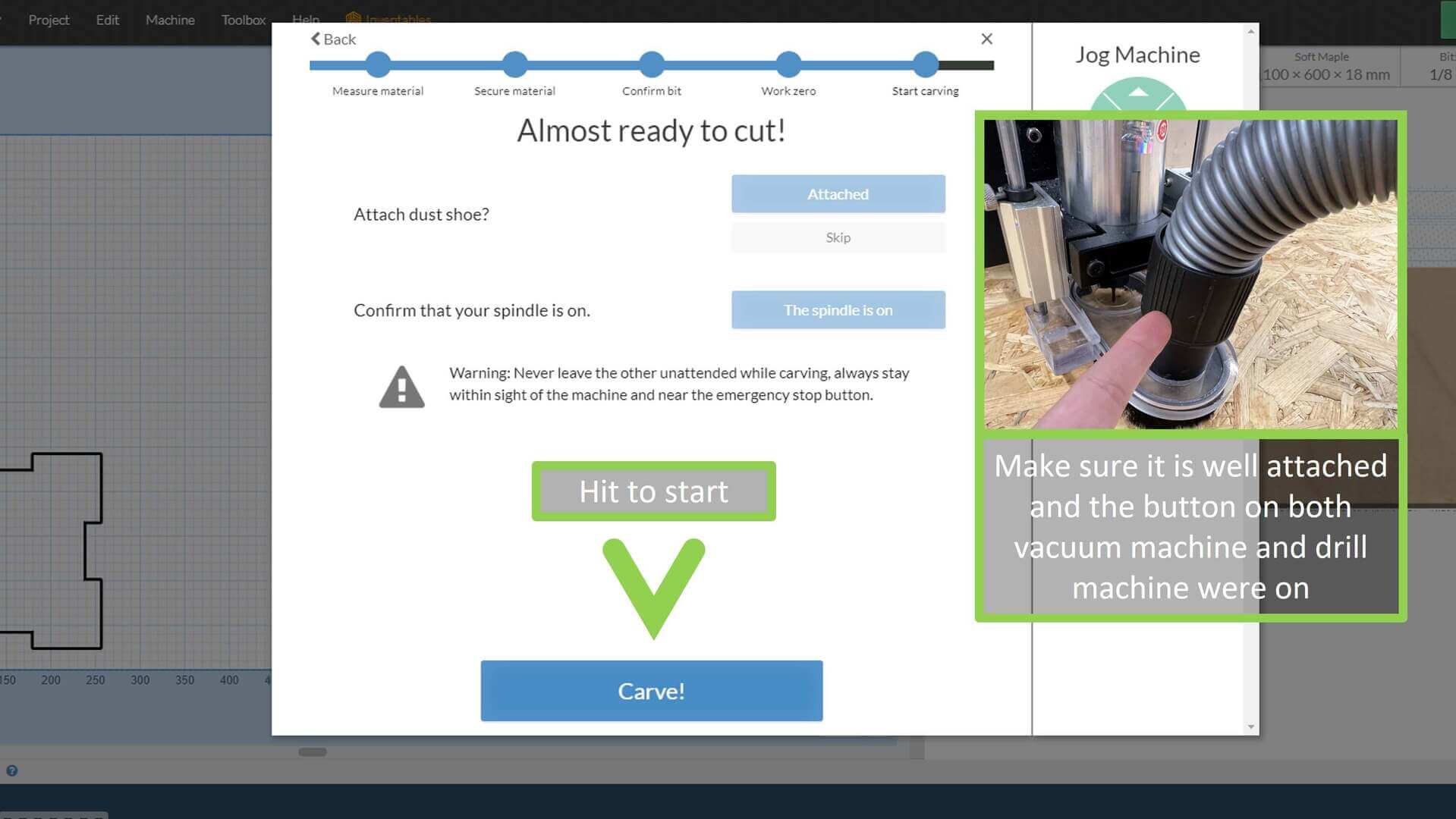
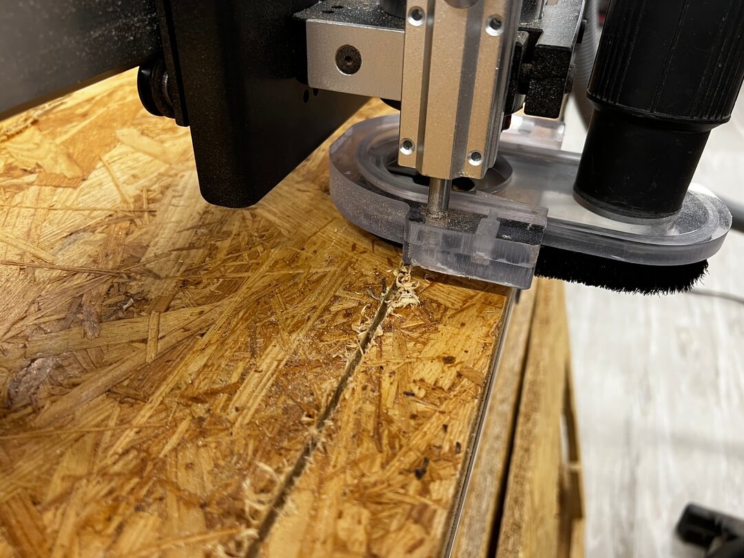
Then start to mill~~
For the biggest part, 800 x 400mm, it took around 40 min.
And I used 3 days and it took around 200 min to finish all the parts.
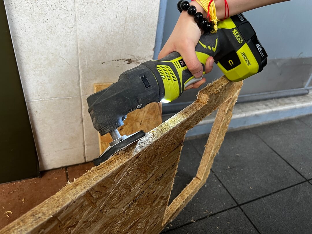
Then I’ve used handheld sander to remove the excess and round it.
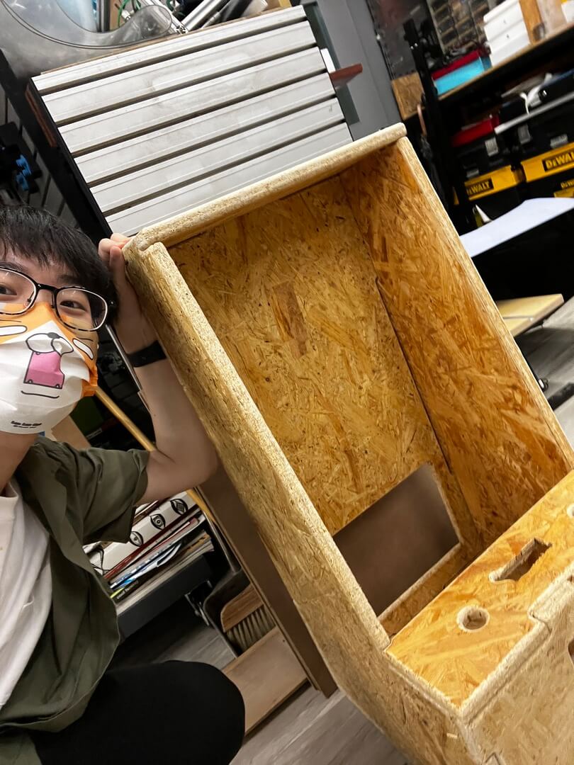
Assembling (Just a test)
It can be joint together perfectly.
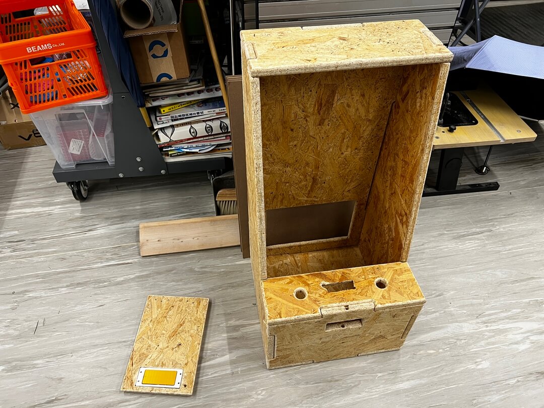
(^^)
Door Hinges & Handle
In this new design, I made a backdoor for the maintenance. Then, I used 3D printed to make the door hinges and door handle with magnet.
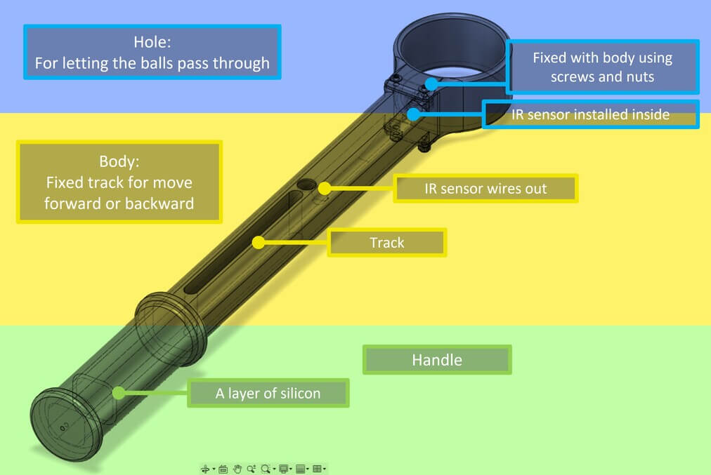
Control Stick
Control Stick can be separate to 3 parts: hole, body, handle.
The Hole part is used for letting the balls pass through and an IR sensor is installed inside. It’s fixed with the body using screws and nuts.
The Body part is designed to have a fixed track for moving forward or backward. And the hole is for the IR sensor wires to come out.
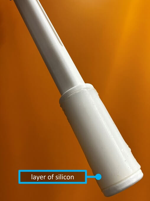
The Handle part is designed for the user to hold and there will be a layer of silicon.
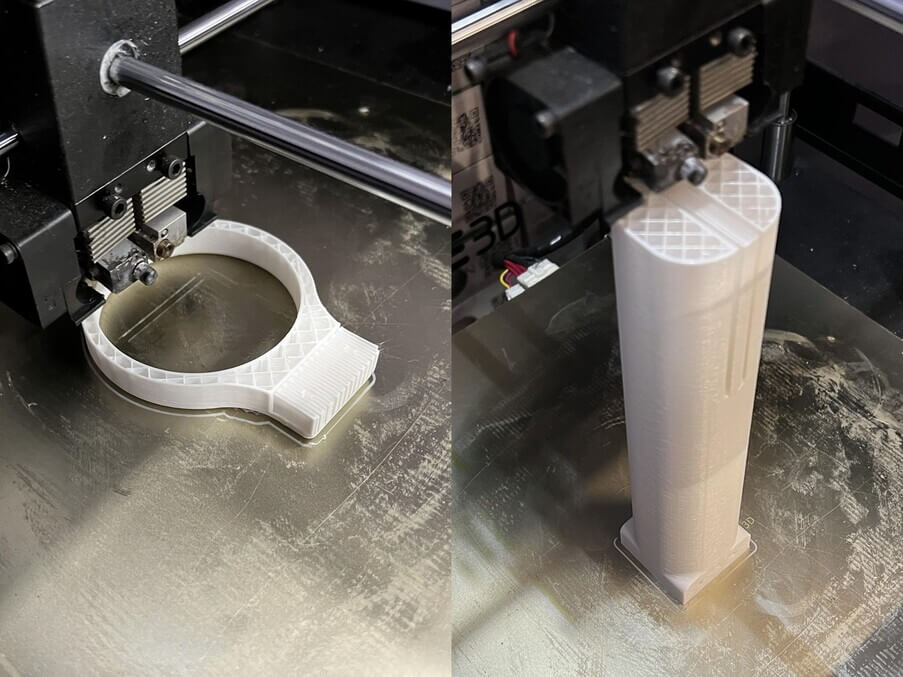
I’ve used RAISE3D N2 Plus to print the parts.
Then I simulated the usage of the Control Stick, and it seems ok.
Then I’ve put the IR sensor inside the side of the hole.

And it fit perfectly.

For the Handle part, I made a layer of silicon on the handle.
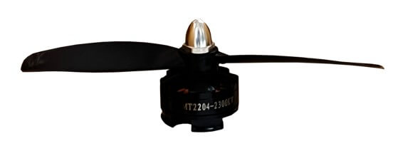
DC motor
For the motor, I choose to use MT2204 KV2300 DC Brushless Motor.
This motor is usually used for 250mm wheelbase mini quadcopters, lightweight fixed-wing copters, indoor 3D airplanes. But for me, I just wanna make some airflow.
Then I modified… changed another propeller. The new propeller makes the wind go up instead of the previous one, going down.
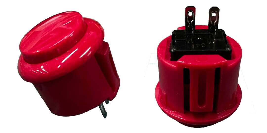
Buttons
For the buttons, I choose to use a 2 pins normally open (NO) push buttons from TaoBao.
One pin connects to the ground and another connects to the signal.
In its default state, makes no electrical contact with the circuit. Only when the button is pressed down does it make electrical contact with the circuit.
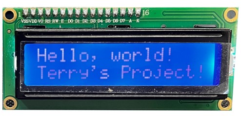
I2C LCD
For the display, I choose to use a 16 x 2 I2C LCD, 16 x 2 is enough for me to show the time and score. And I properly will choose to use ESP32 for making my board so why not I2C ^^ (For you don’t understand, ESP32 supports I2C).
| I2C | ESP32 |
|---|---|
| SDA | GPIO 21 |
| SCL | GPIO 22 |
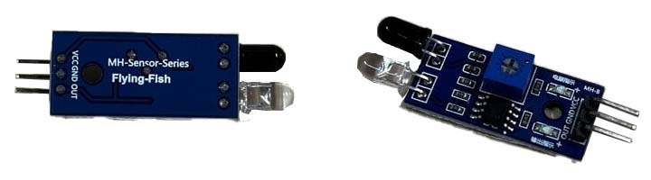
IR sensor
For the sensor that detects balls, I choose to use an active infrared(IR) sensor.
It measures and detects infrared radiation in its surrounding environment and it both emits and detects infrared radiation.
For more details, active IR sensors have two parts: a light-emitting diode (LED) and a receiver. When an object comes close to the sensor, the infrared light from the LED reflects off of the object and is detected by the receiver.
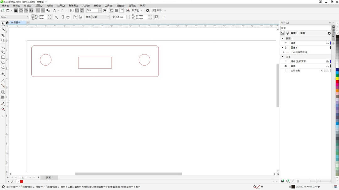
Front & panel cover
For the front cover and the panel cover, I choose to use a laser cutting machine to cut the acrylic sheet.
Logo Design
Logo design done at week 3, click HERE to visit.
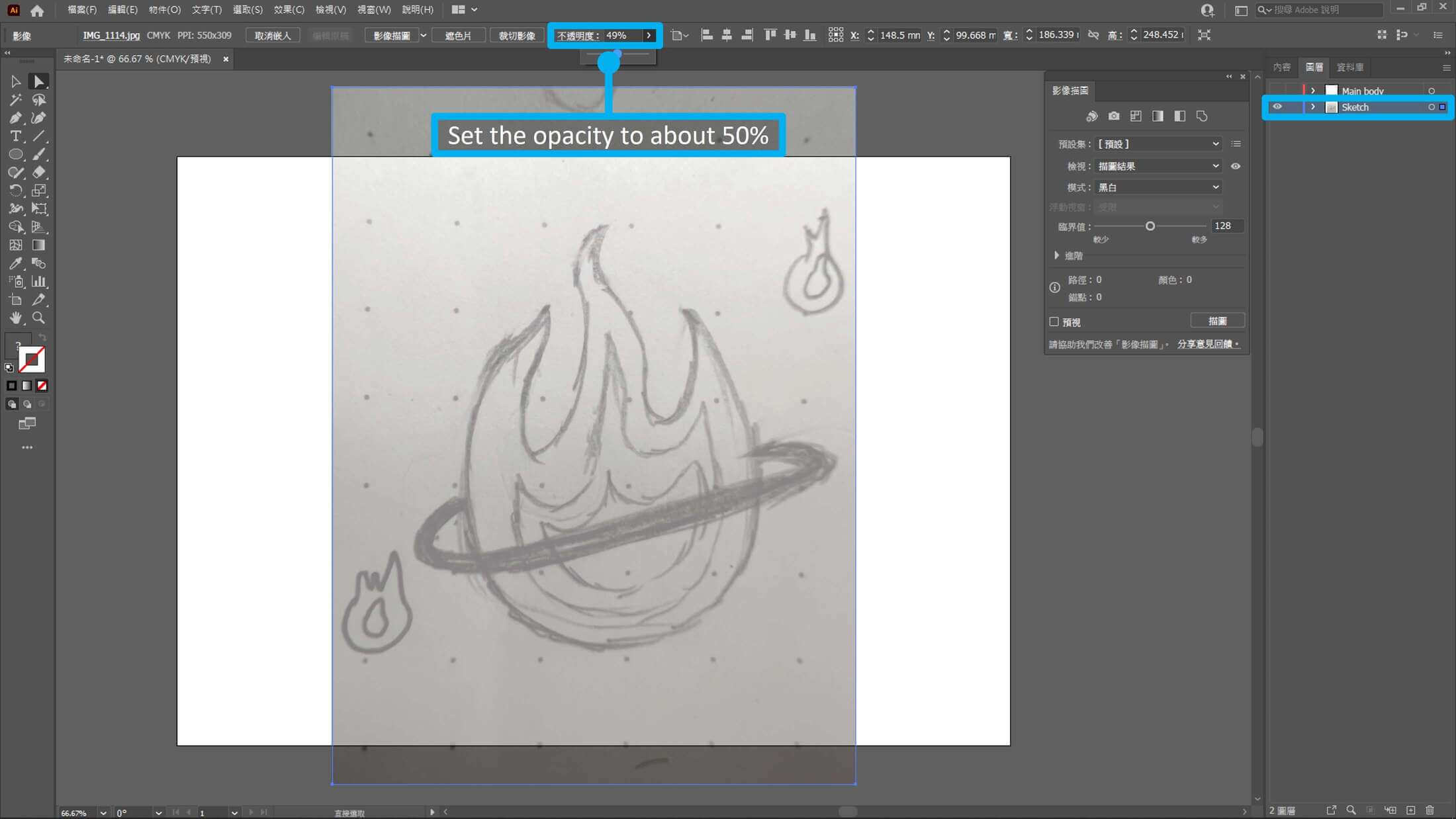
Adobe Illustrator can create or edit vector graphics. It is perfect for designing a logo for a company or a product.
I had never used Ai before so I look up tutorials on Youtube, Chinese Illustrator tutorial playlist.
First, I put my draft into the Ai and set the opacity at about 50% to make me better for the rest of the steps.
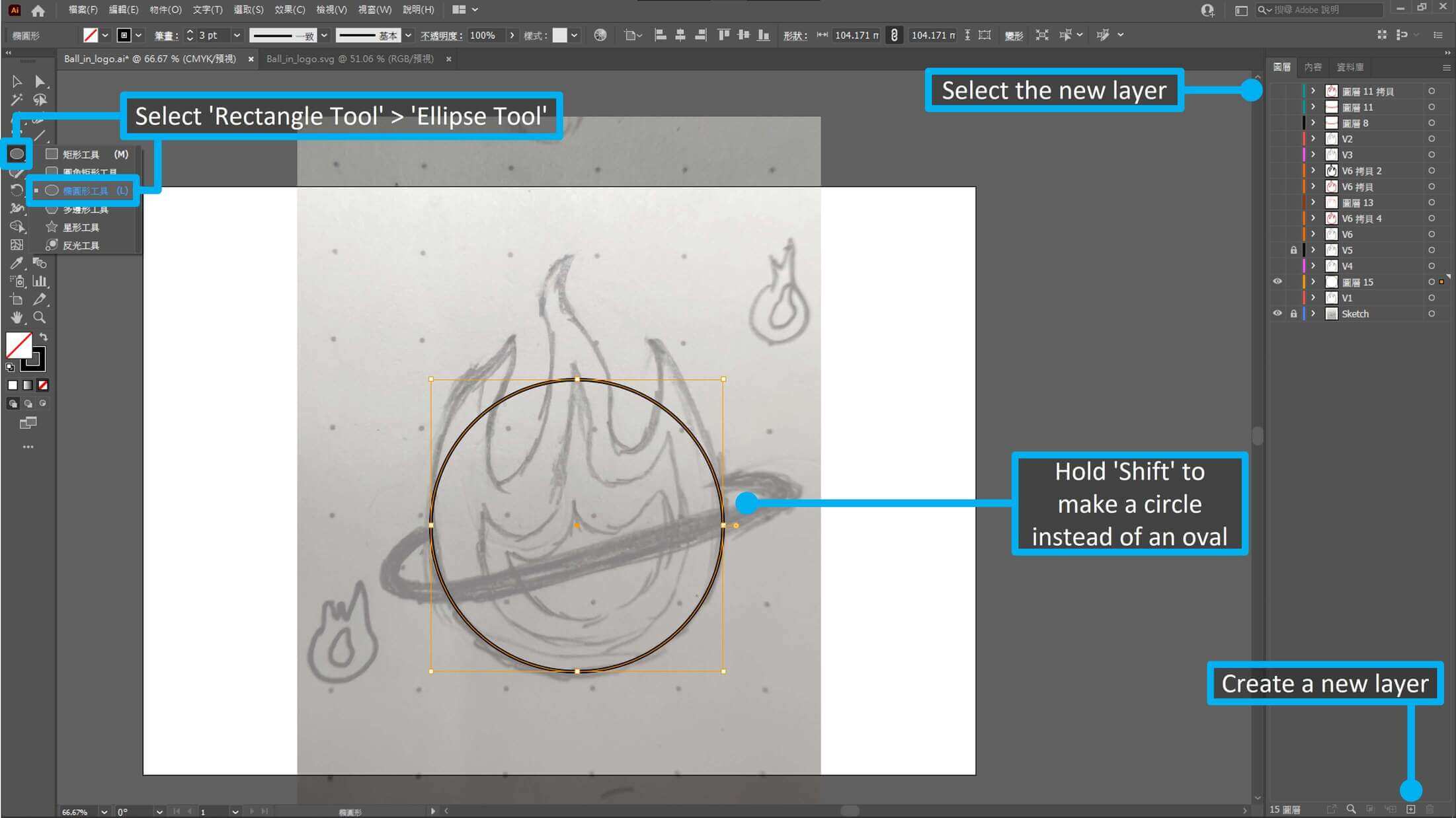
Second, I create and select the new layer. Then select the ‘Rectangle Tool‘M > ‘Ellipse Tool‘L in the toolbar. After, hold Shift and Left Button to create a cirle.
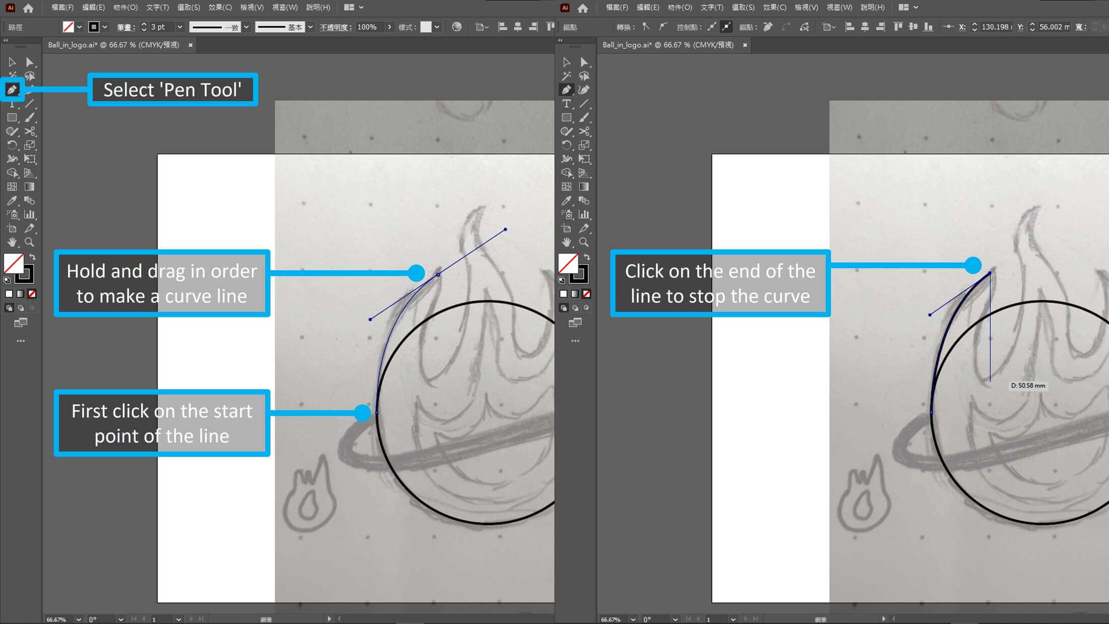
Third, I select the ‘Pen Tool‘P to make a curve line. Left Button on the circle to be the start point of the line, then hold and drag the cursor to make a curve line. After, one click on the end of the line to stop continuing the curve.
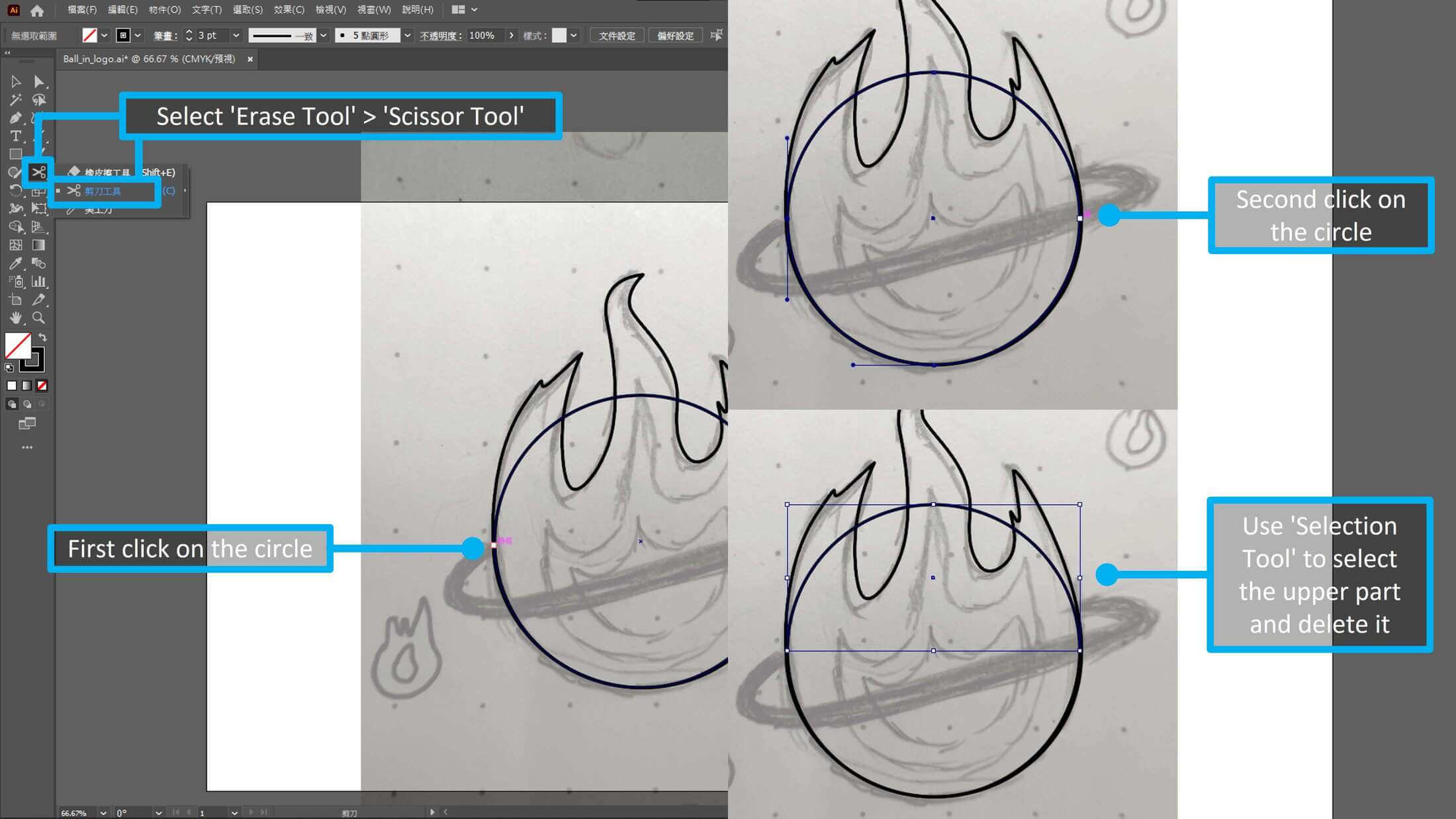
Fourth, after I finish the outline of the fire, I select ‘Erase Tool‘Shift+E > ‘Scissor Tool‘C. Then click 2 spots on the circle and use ‘Selection Tool‘V to select and delete the upper part of the circle.
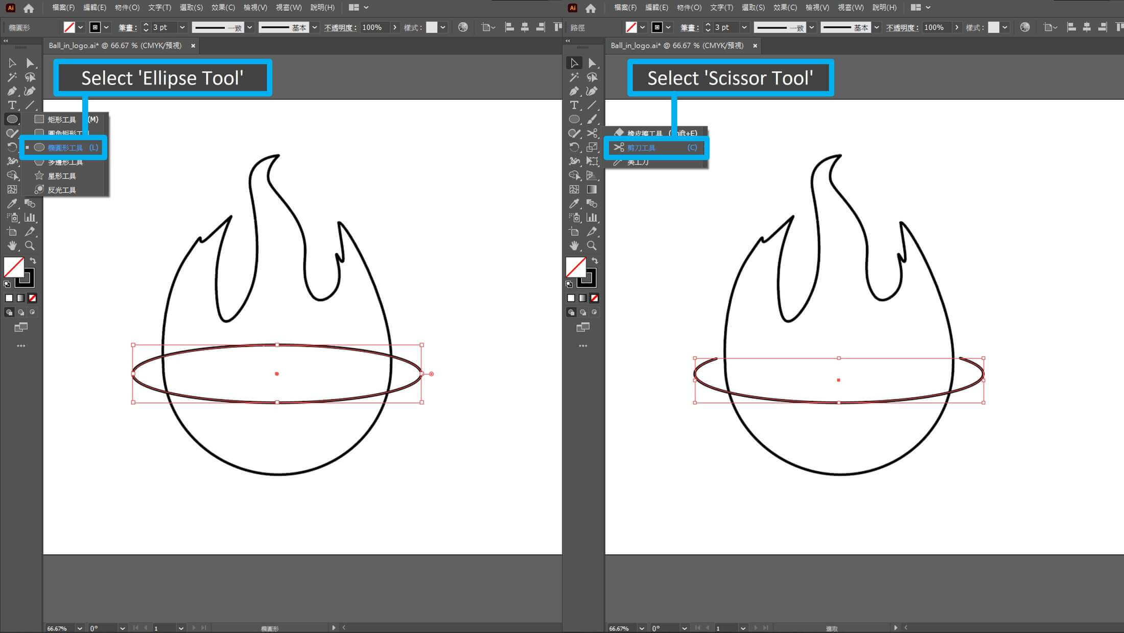
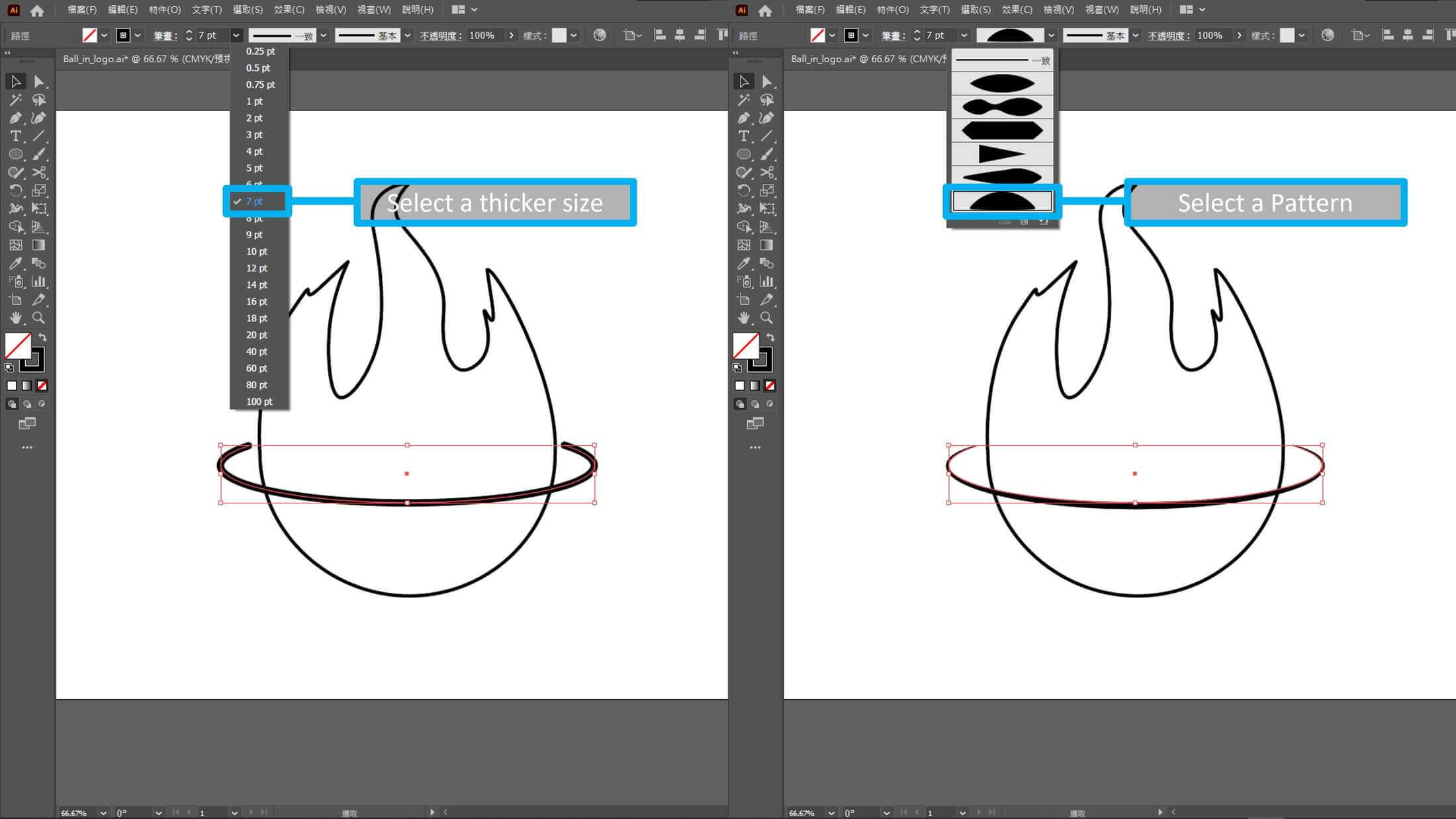
Fifth, same as before, I use ‘Ellipse Tool‘L and ‘Scissor Tool‘V to make a ring for the main body. Then, select a thinker size and pattern for the ring.
Sixth, some adjustment, added a ball inside the fire and text of the project name.
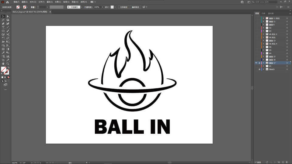
✅Done.
