5. Electronics production
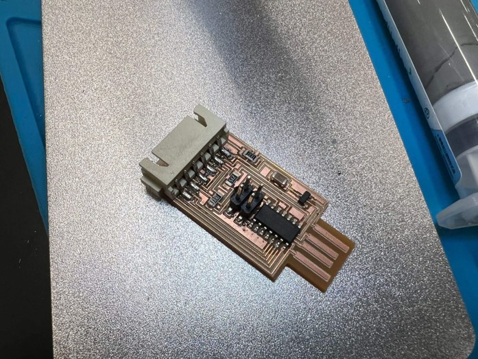
This week I worked on making an in-circuit programmer that includes a microcontroller by milling and stuffing the PCB.
Group assignment
This week of group assignment, We characterize the design rules for our in-house PCB production process. Click HERE to see more detail of the group assignment.
Individual assignment
Heroshot

First trial
Documents
I used Mods to generate .nc file
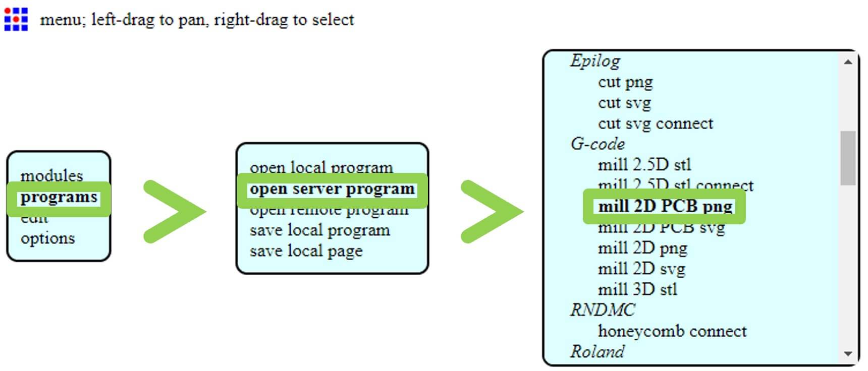
Step 1: Open Mods > Right click > programs > open server program > G-code: mill 2D PCB png.
select ‘mill 2D PCB svg’ if you input file type is svg.
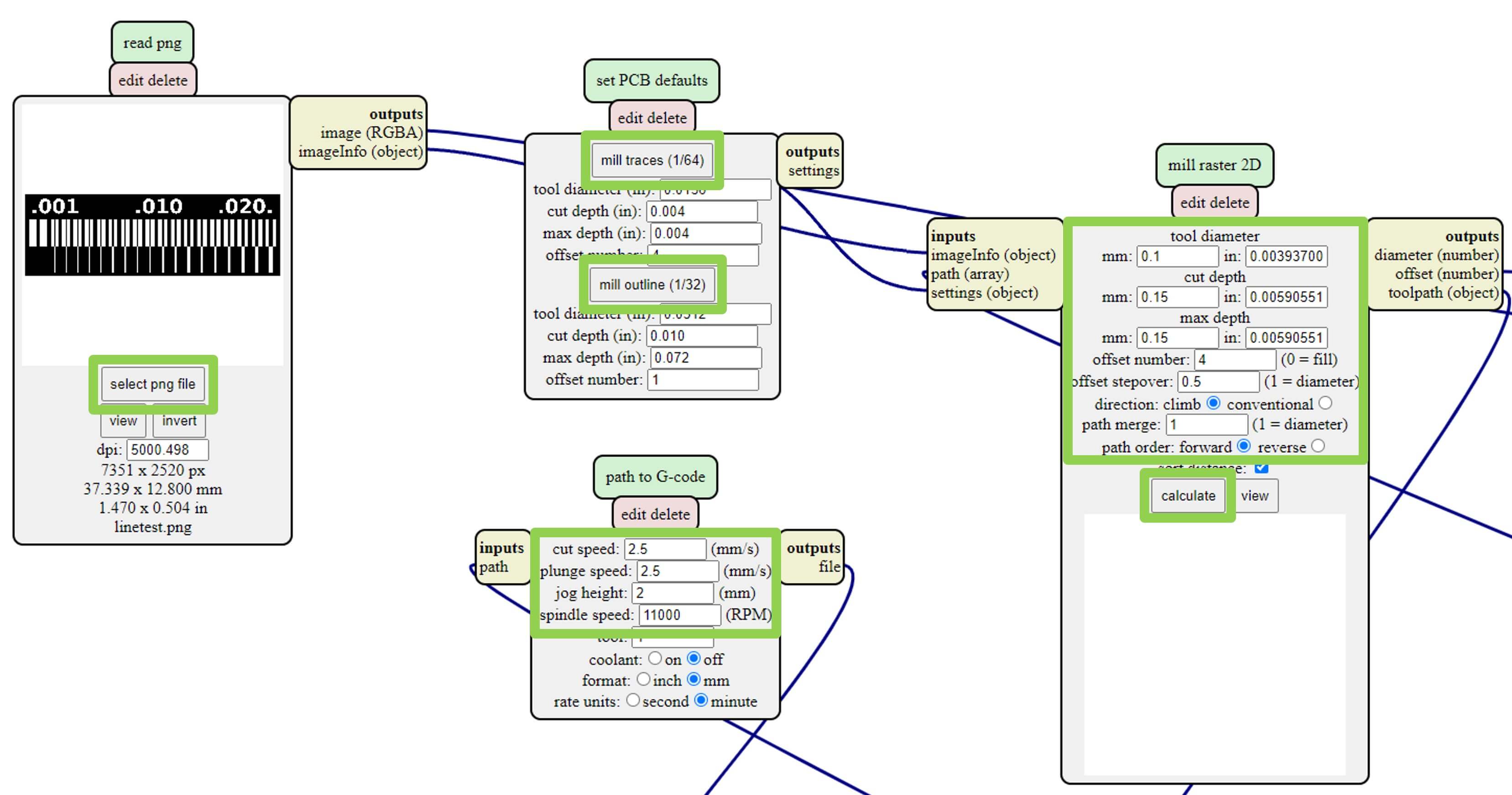
Step 2: Select the image, and change the settings to you wanted or the machine needed, like tool diameter, cut depth, speed, offset… After all settings done, click calculate.
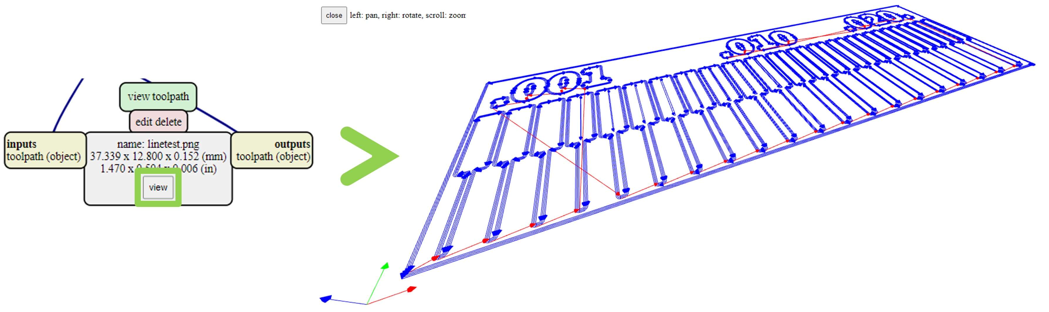
Step 3: Inspect the generated cut path files in the ‘view toolpath’ module at the bottom by clicking ‘view’ button.
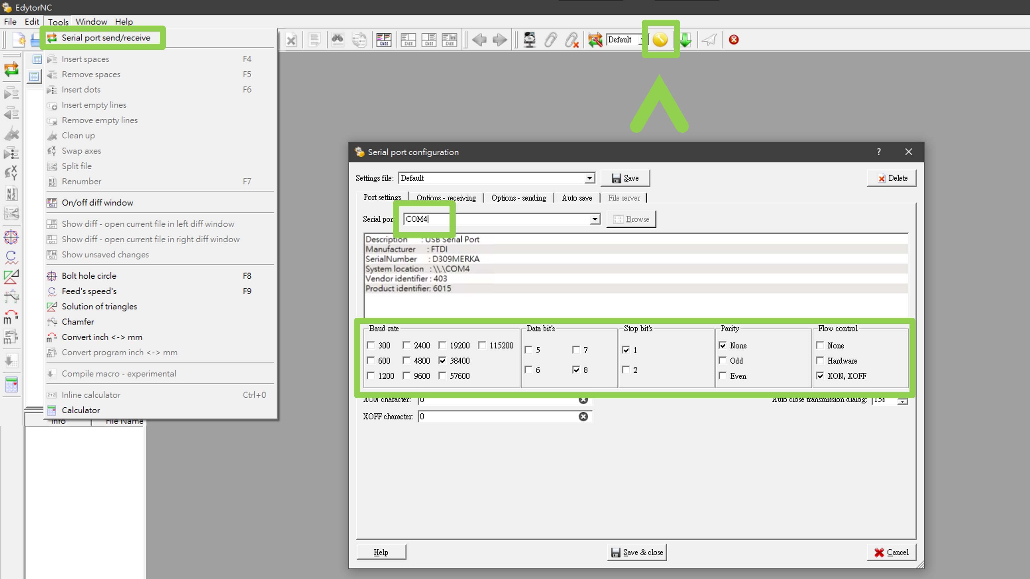
Then I used EdytorNC for communication.
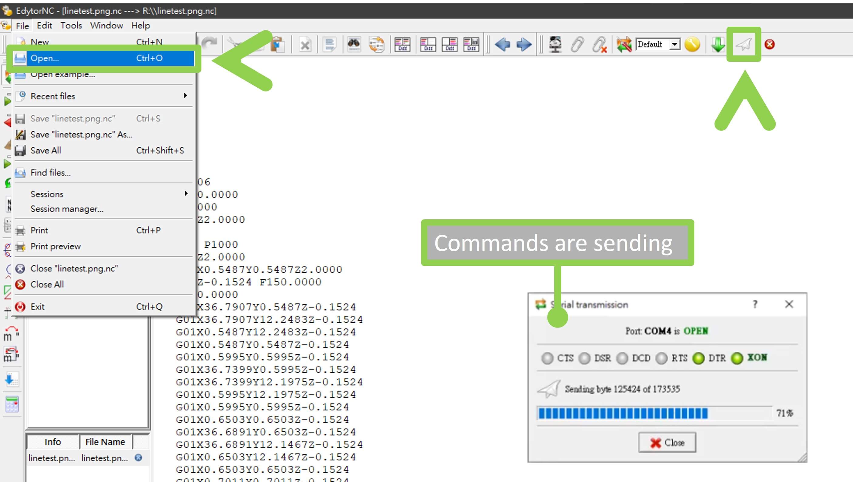
Step 4: Click Tools > Serial port send/receive.
Step 5: Click on the yellow button on the function bar, and select the correct COM port and settings.
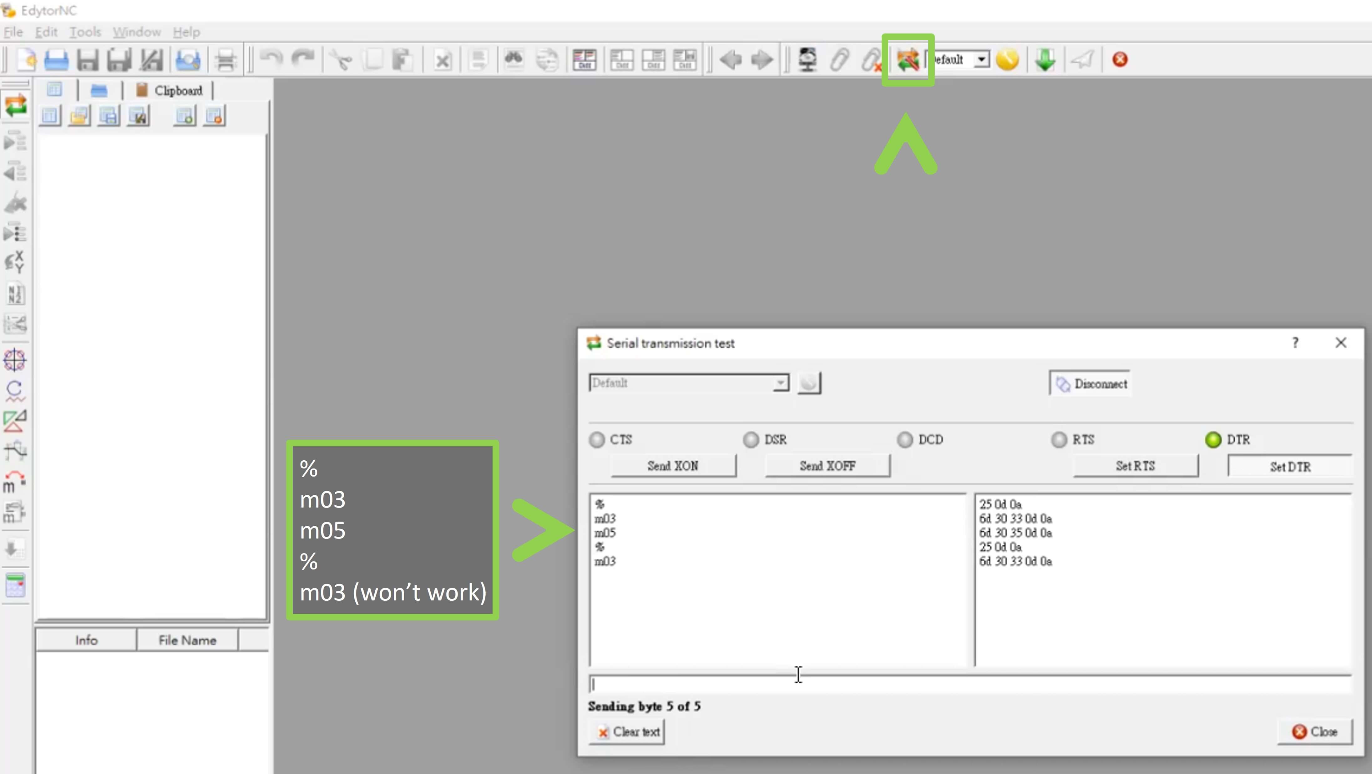
Step 6: Test for the communication between the computer and the machine. Click the button on the left of the selection textbox. and type ‘%’ to let know machine know this is the beginning, then ‘m03’ to test is the machine do run your command. If it is ok, then ‘m05’ to stop the spindle from turning, and % for denote the end.
Command % To denote the beginning and end m03 To start the spindle turning clockwise m05 To stop the spindle from turning Here are some Chinese documents of using code on CNC machine
CNC銑床程式製作功能一覽表
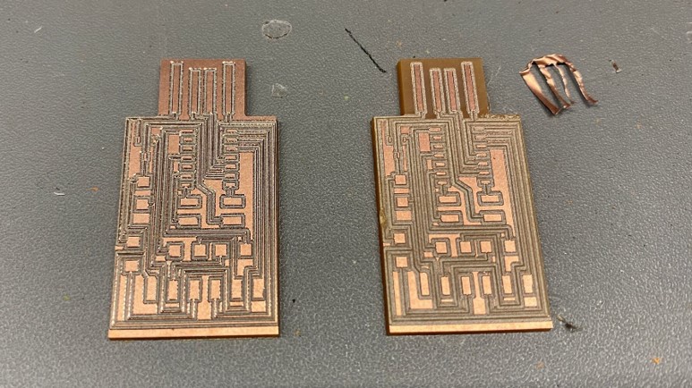
The board are ready to be mill.
Step 7: Select the file and send it to the milling machine by click the paper airplane button.
Milling
week05_milling from TerryAU on Vimeo.
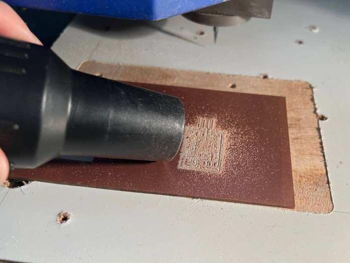
Then clean up the dust on the PCB board.
I remove the copper near the USB port in case of a short circuit.
week05_remove from TerryAU on Vimeo.
Soldering
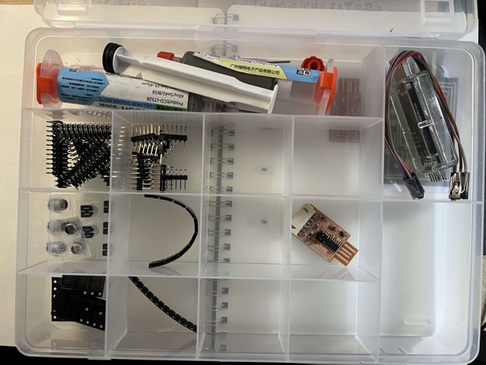
All of us have this box to organize and place components. Lovely.
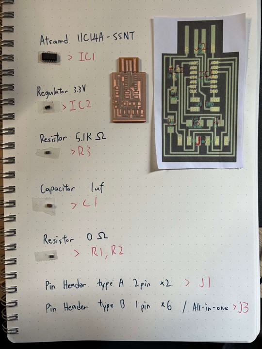
And I made a list of what we are going to solder on the board.
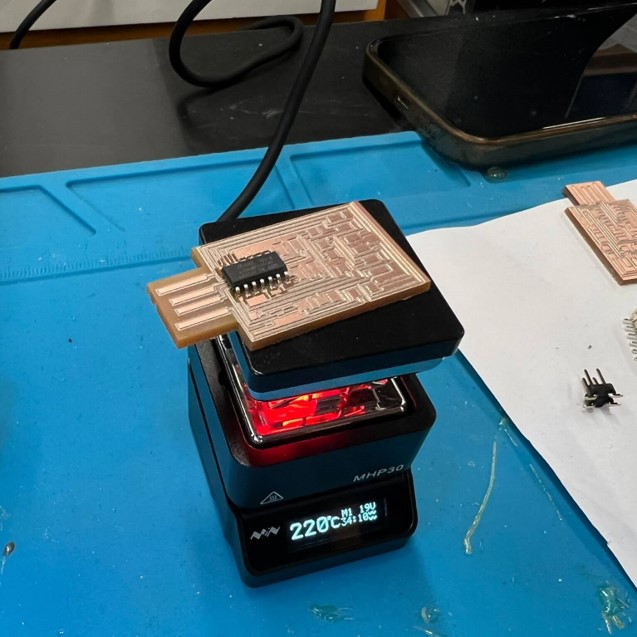
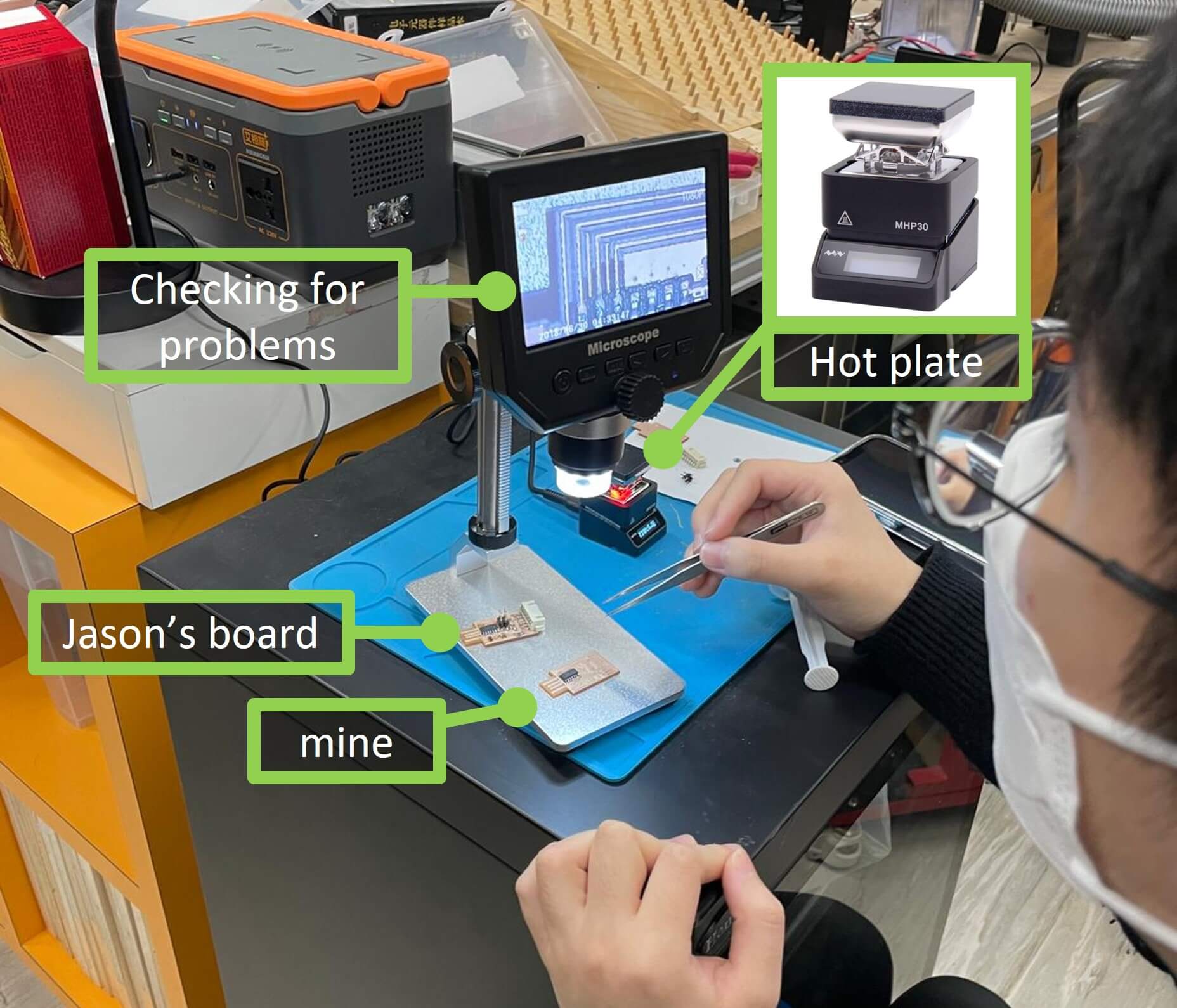
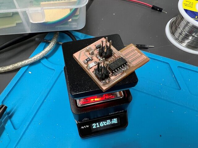
Then I use a hot plate to assemble all parts.
The reason why I used a hot plate instead of iron is the components are tiny and it’s hard to solder small things in a small board, and it’s easy to touch and melt components by accident.
After soldering, I went home and try to connect to a computer and install the driver. Then, the regulator blows up with a spark. And I freaked out.
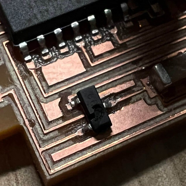
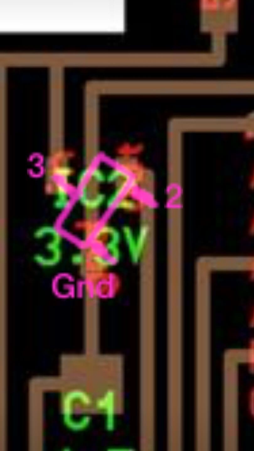
Then I told it to the instructor and said because the pin on the regulator we are using isn’t the same as Neil’s. So we need to rotate it to place it in the right position.
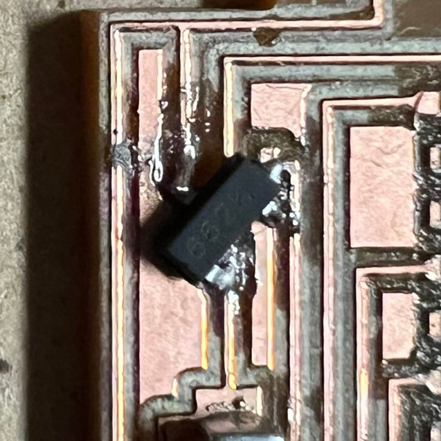
Then I remove the cracked one with iron and replace it with a new regulator.
Programming
Then I try to program it and install the driver.
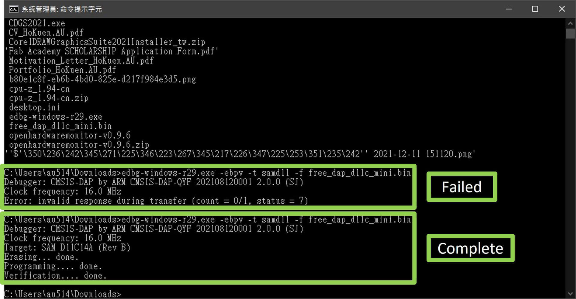
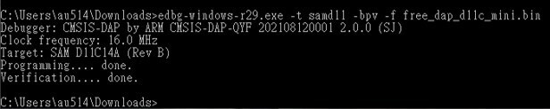
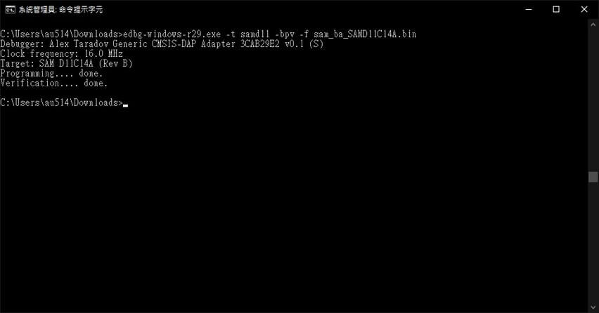
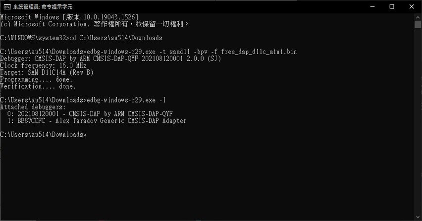
Downloaded free_dap_d11c_mini.bin and edbg-windows-r29.exe in order to install. Open CMD and type:
In your CMD, you can use
cd <dir>to change directory,mkdir <name>to make directory,lsto list what files are in the current directory.
Troubleshooting
As you can see the .bin file seems to installed into the chip, but the problem is the computer can’t recognise it. No COM port was shown up.
Maybe i got issues of:
- The USB port of the computer broke (not much possible)
- Wrong .bin file
- edbg not support
- Components were broke
- Bad soldering
Second trial
Then we discussed and find out that the board we milled isn’t the programmer we want, we should use a 4pin output programmer.
Milling
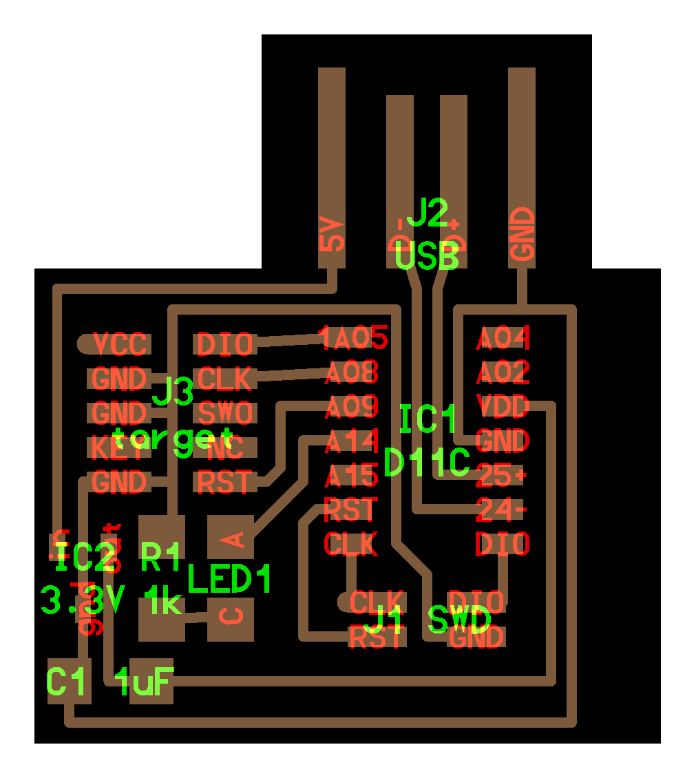
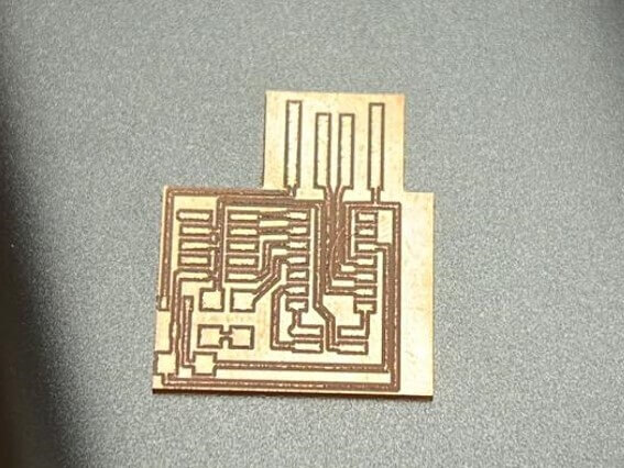
So I’ve milled a new PCB board using This PCB design to try is it work to be a programmer.
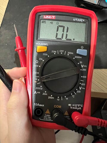
Then I went home and solder it, but I am not sure is there any short-circuit. And I didn’t grab a multimeter at the lab so I ran to the nearest shop and bought one. It cost me around 10.6 USD.
Soldering
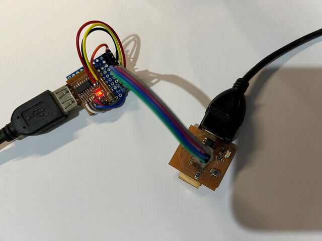
Because the original design of the pin holder is smaller than the one I using, so I need to do “flying wires” to try out the program.
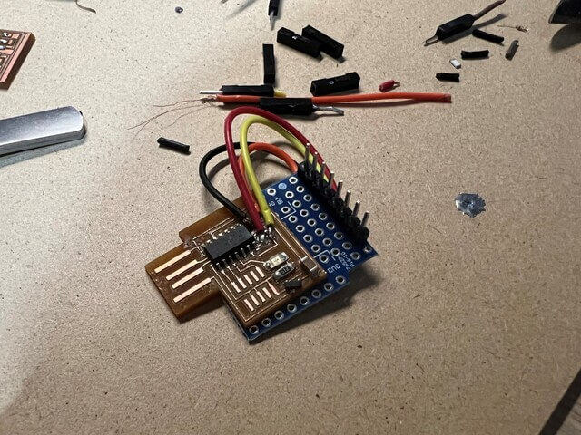
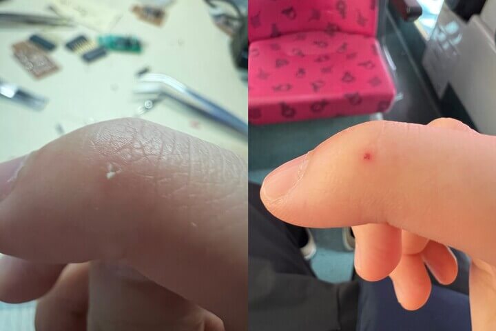
And during soldering, I got hurt by the iron. How careless I am…
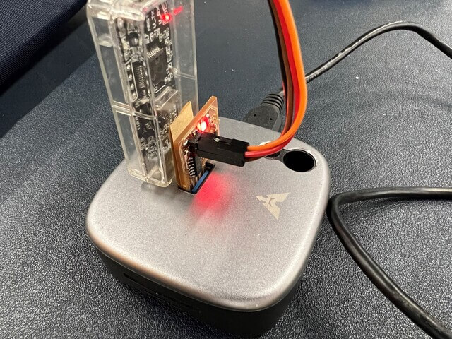
Then I saw it turn red when I am on the way to Fablab. :(
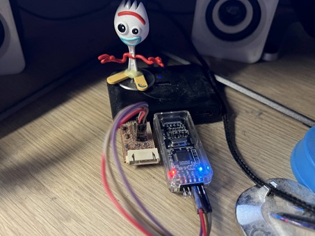
I plug it into my pc port when I finish half of the “flying wires“
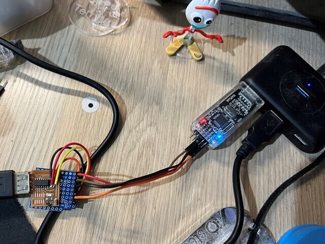
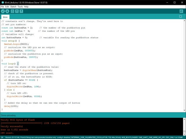
As you can see, it successfully writes in the .bin file into the chip.
Then I keep going on to the rest of the “flying wires“
Programming
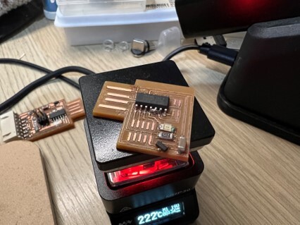
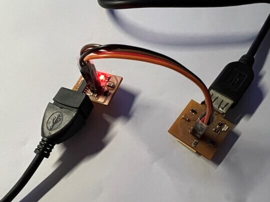
I connect the programmer “Debug4Terry” with the blinking board “Blink4Terry” and try to program it.
Write in successfully!
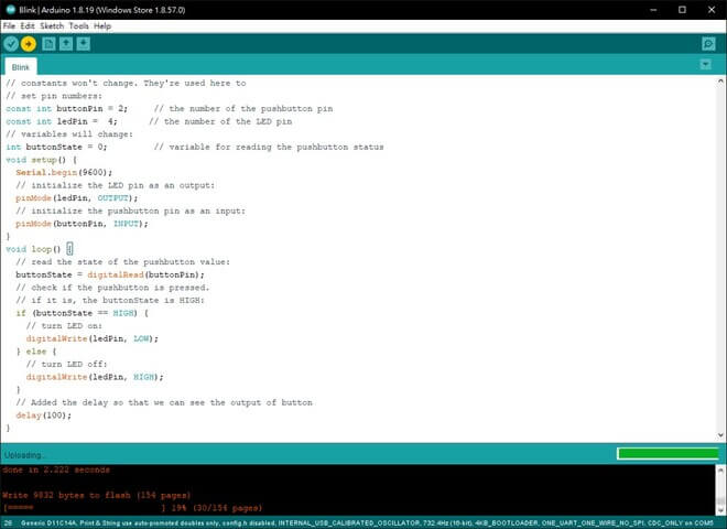
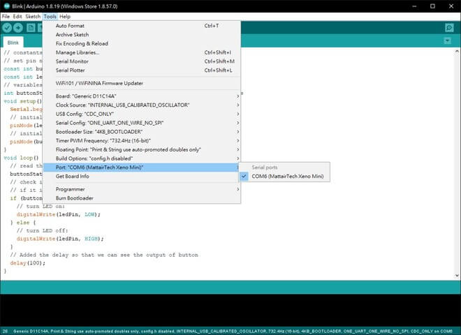
Then I try to program it with Arduino IDE.
Third trial
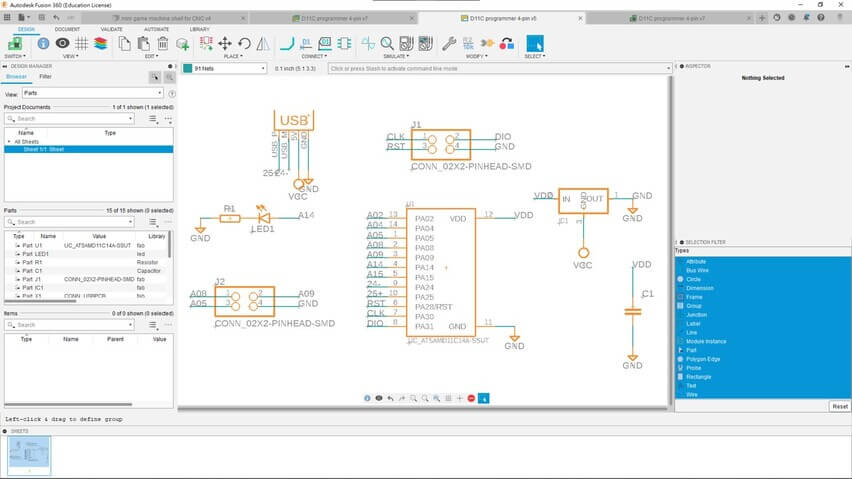
Designing
But “flying wires” is fail to reach the requirement so I decided to design my own programmer with Fusion 360.
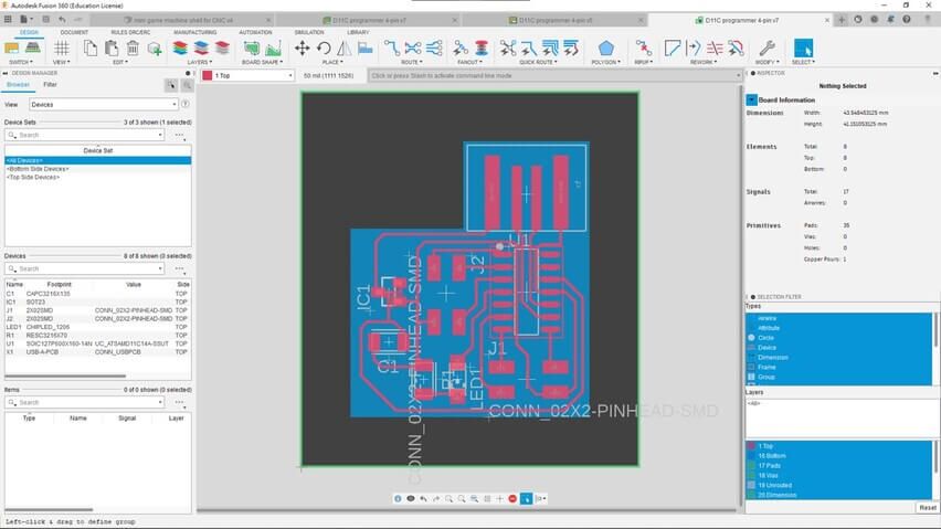
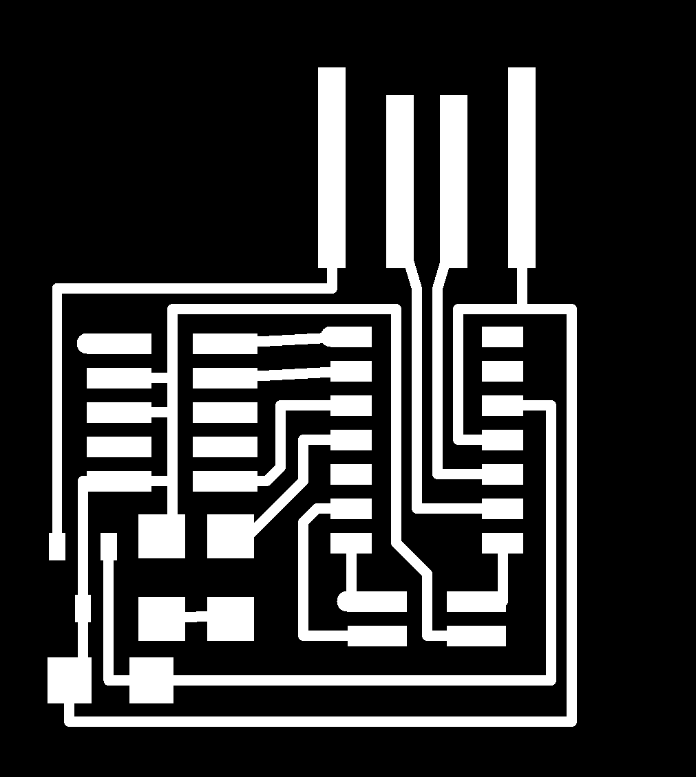
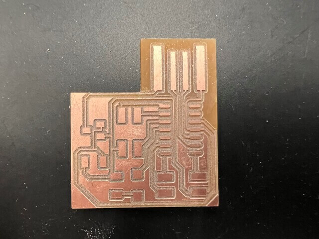
Milling
Then rap off the copper on the head of the USB and ensure that there are no short-circuit.
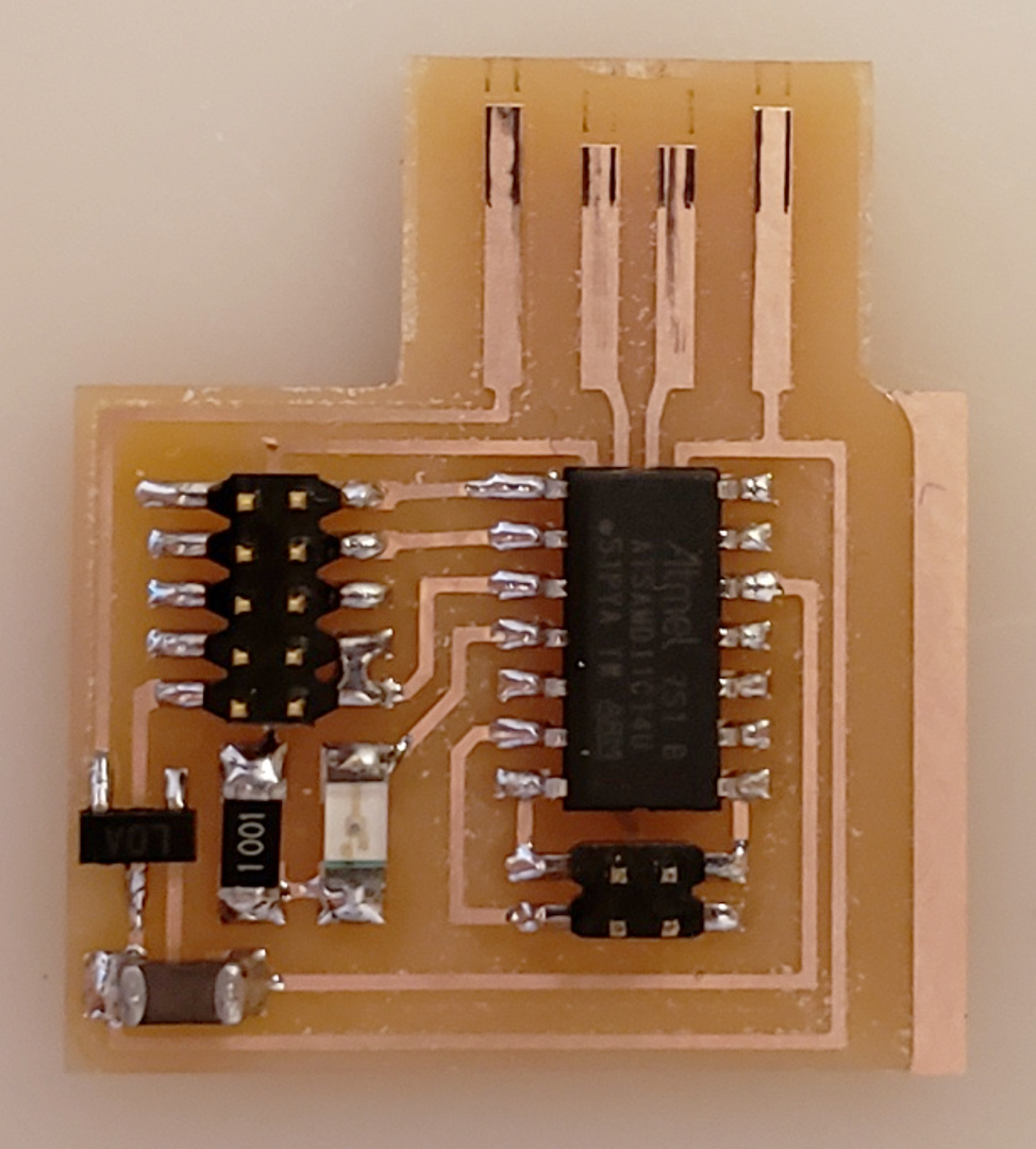
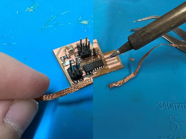
Soldering
Because I add too much paste and the legs(pin) are connected together, I need to clean up it.
Programming
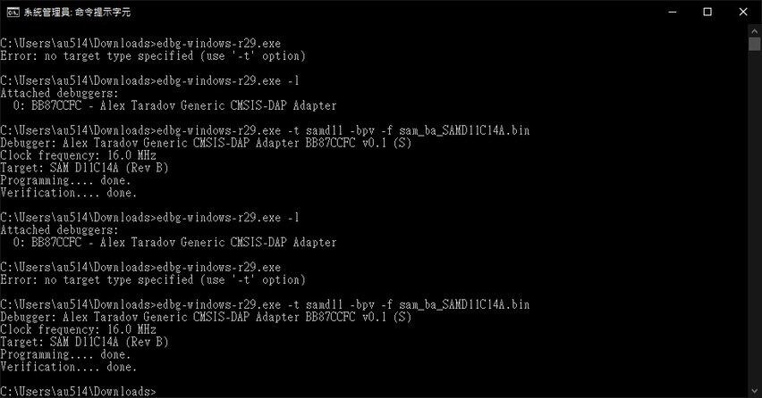
Programmer .bin file write in successfully!
And there are two different programmers shown up in the list. Yeah!
Then same as before, I connected my own programmer with the blink board and try to program it.
Then turns out it works! My lovely programmer.