7. Electronics design
This week I worked on redrawing one of the echo hello-world boards with a button and LED.
Group assignment
This week of group assignment, We use the test equipment in your lab to observe the operation of a microcontroller circuit board. Click HERE to see more detail of the group assignment.
Individual assignment
Heroshot

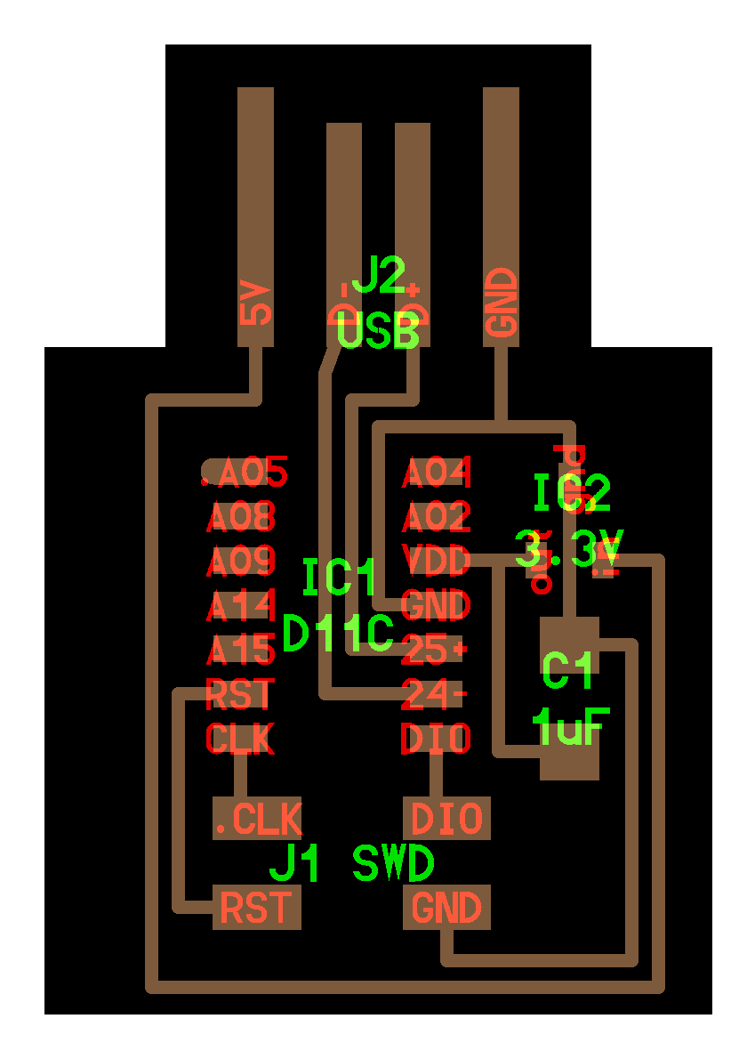
This week assignment I decided to make a board design according to D11C-echo-4 pin
Software
For design the PCB borad, I used Fusion 360 to do that. Fusion 360 acquired Eagle so it is mostly the same on Fusion 360.
Components
To start with, I clarified what components I will using.
| Components | Type | Quantity |
|---|---|---|
| ATSAMD11C | Microcontrollers | x1 |
| 1K Resistor 1001 | Resistors | x2 |
| 1uF Capacitor | Capacitor | x1 |
| 3.3V Regulator 662K | Regulator | x1 |
| 1.8~2.2V Red LED | LED | x1 |
| Press Button | Switch | x1 |
| 2x2 Male Pin Header Connector | Pin Header | x1 |
| 0 Ohms Resistor 000 | Resistors | Depends on usage (x1 for me) |
Designing Schematic Diagram
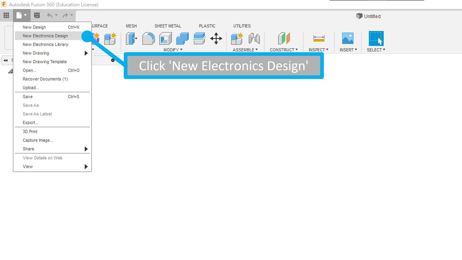
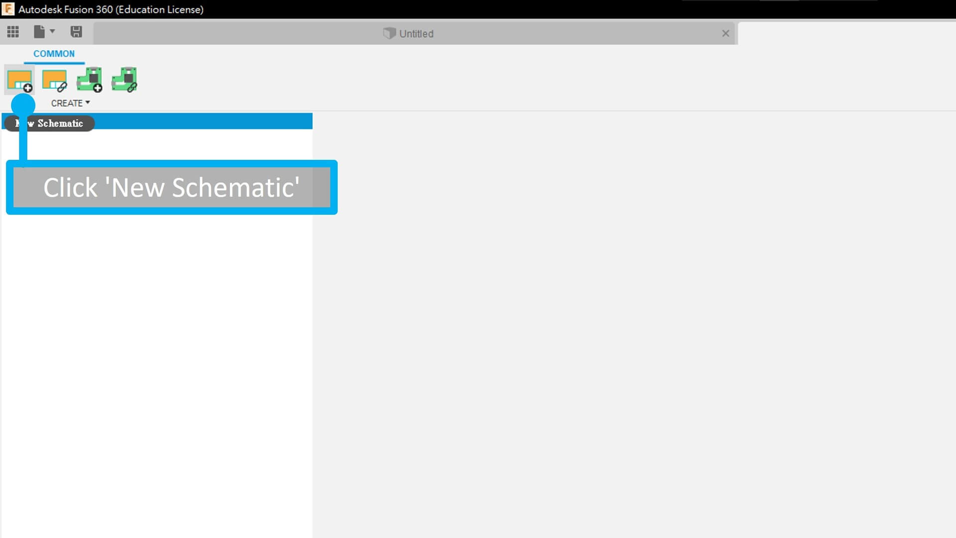
Then, In the Fusion 360, click ‘New Electronics Design’ for open up a page for designing the PCB circuit and board. Then click ‘New Schematic’.
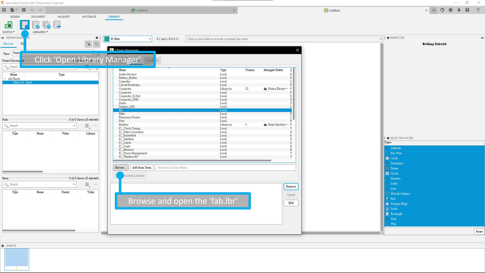
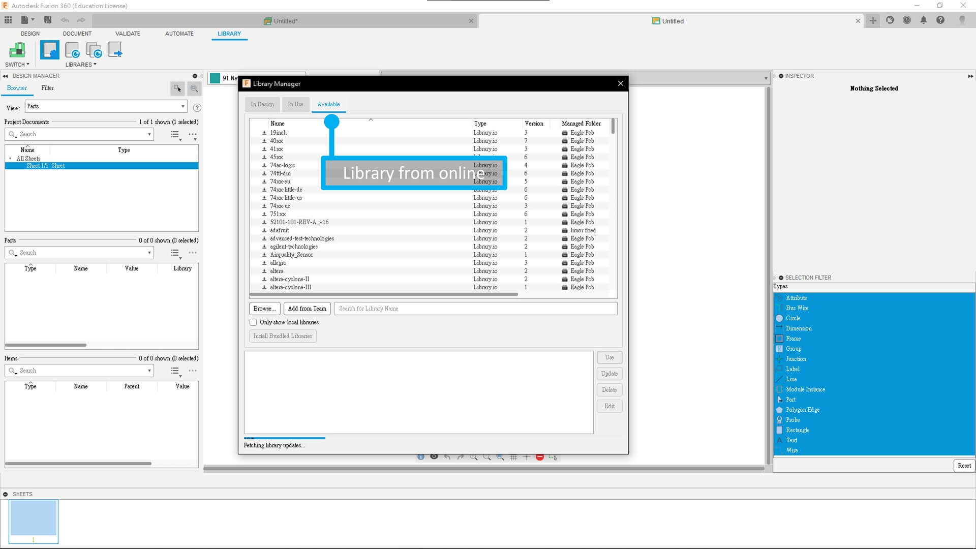
Then, download fab.lbr, the electronics libraries. So that you can use the component provided by fab. By clicking ‘Open Library Manager’ in Library list, then browse and open the ‘fab.lbr’ file.
You can also grap library online, so we can use components which the software and fab didn’t provided. Library from online maybe able to fulfill what we want.
Then click ‘Add Parts’ for open up the components page, or you can type ‘add’ in the command line, it’s the same.
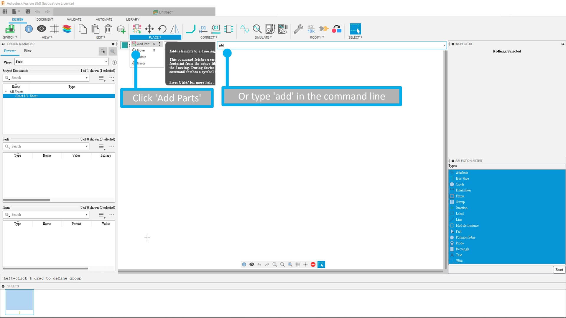
detail of adding parts will be update soon…
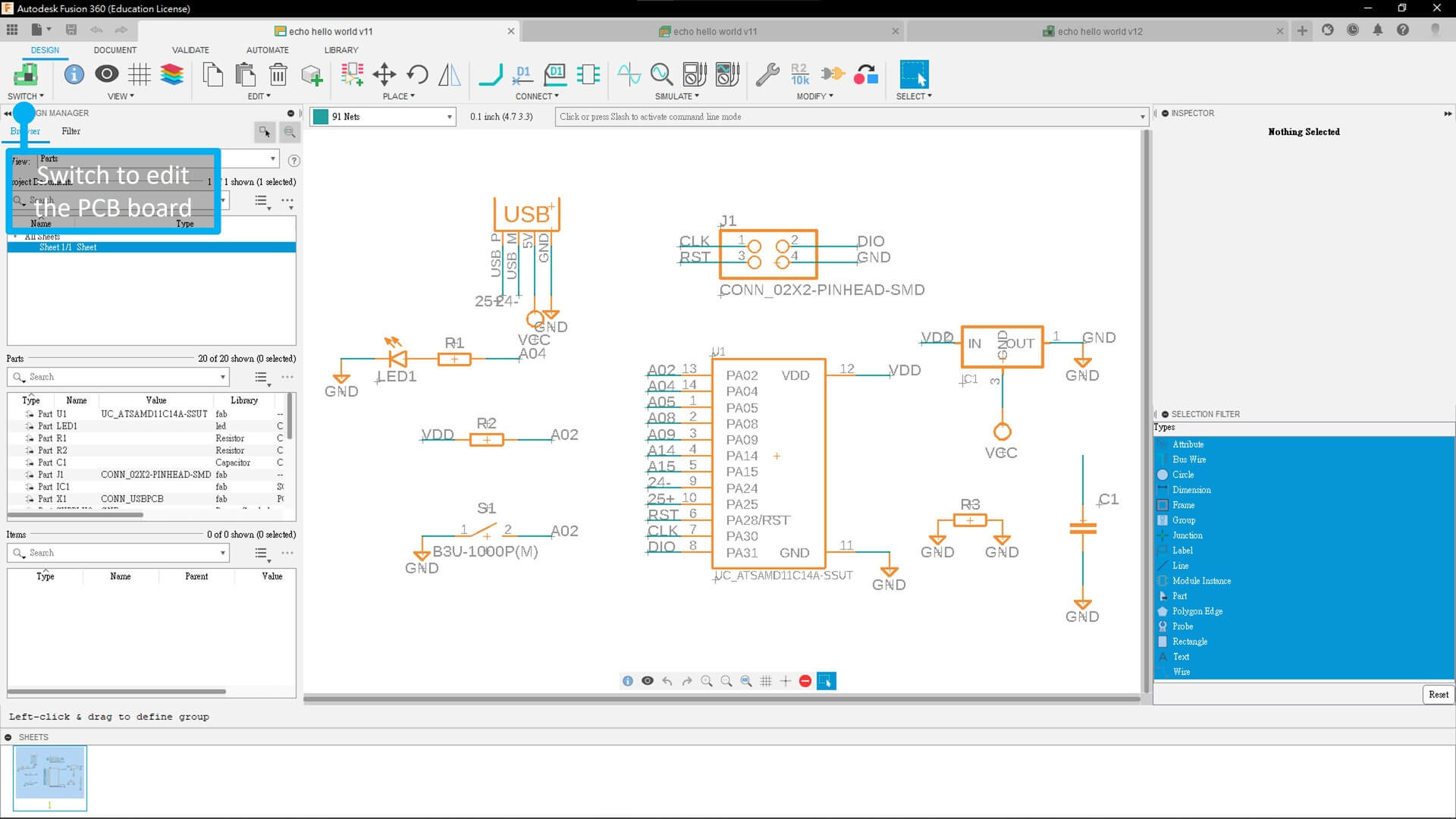
Designing PCB
After finsished designing the schematic diagram, click the top left PCB icon in order to switch to PCB design mode.
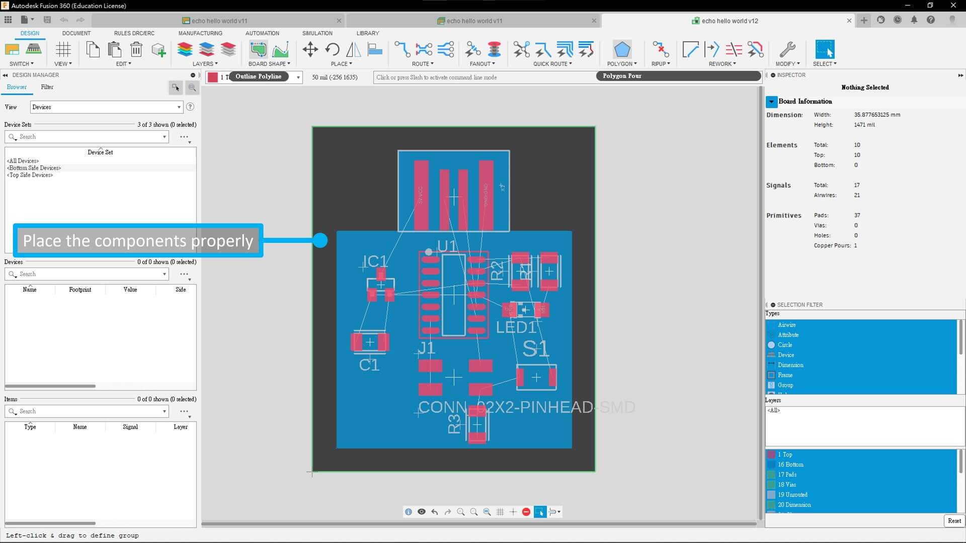
The you will see the components are messly. The components need to be placed properly. There are no auto place function, don’t be lazy.
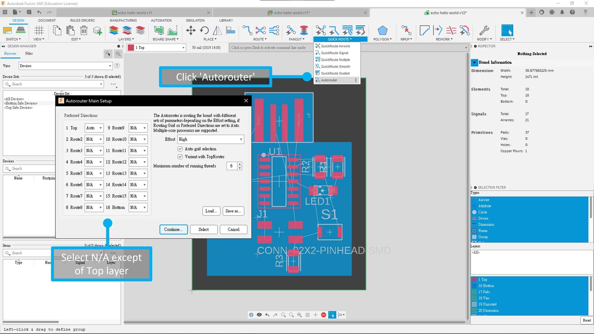
After that, Click ‘Autorouter’ to auto connect all the line, Remember select top layer only. And you can also edit the effort and number of threads you want use.
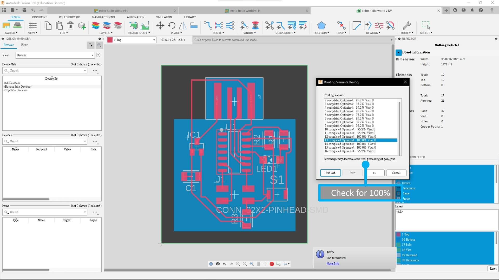
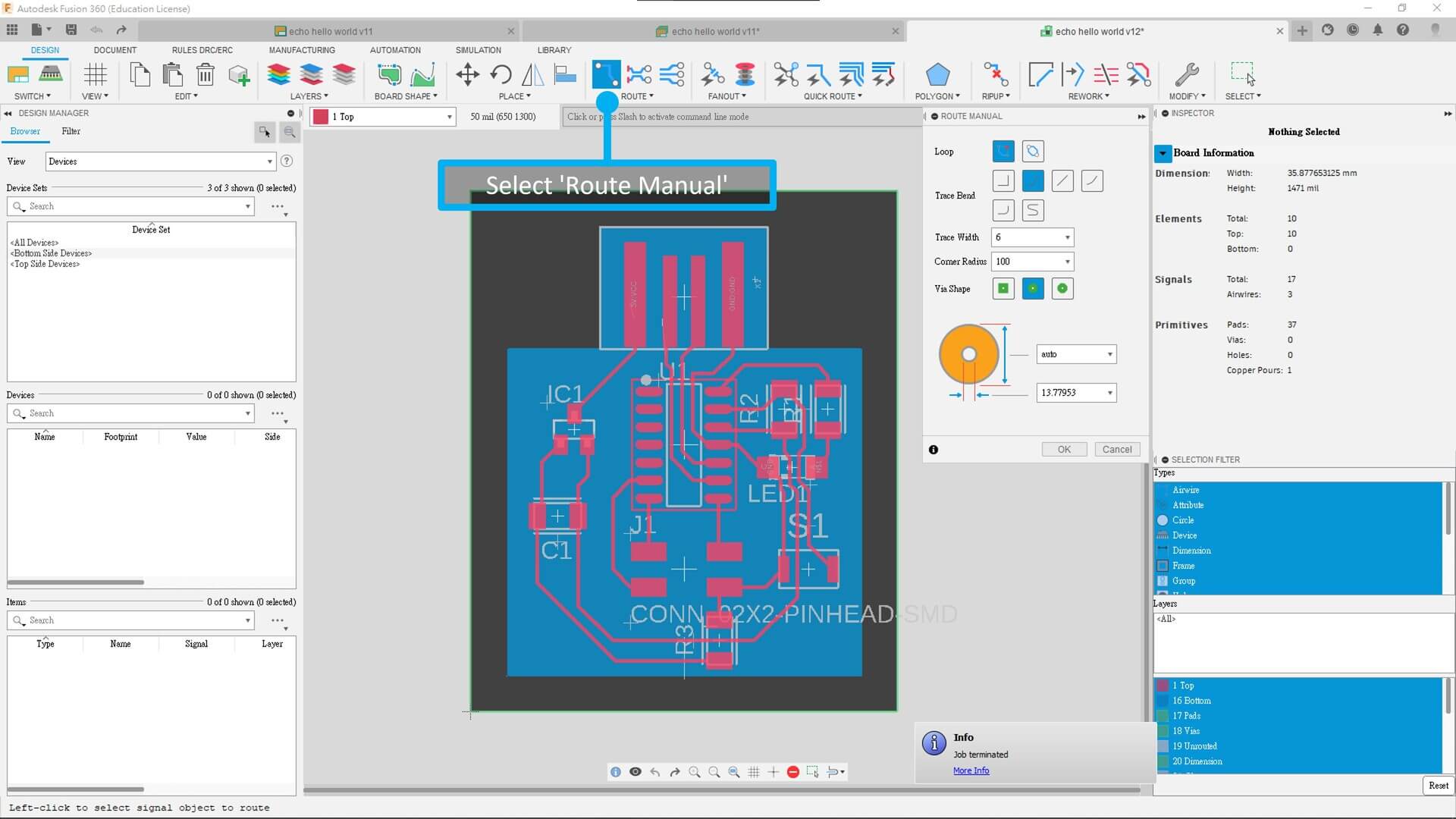
Then check is there any 100% done. If no, then try to change the components’ position. If still, do it manual.
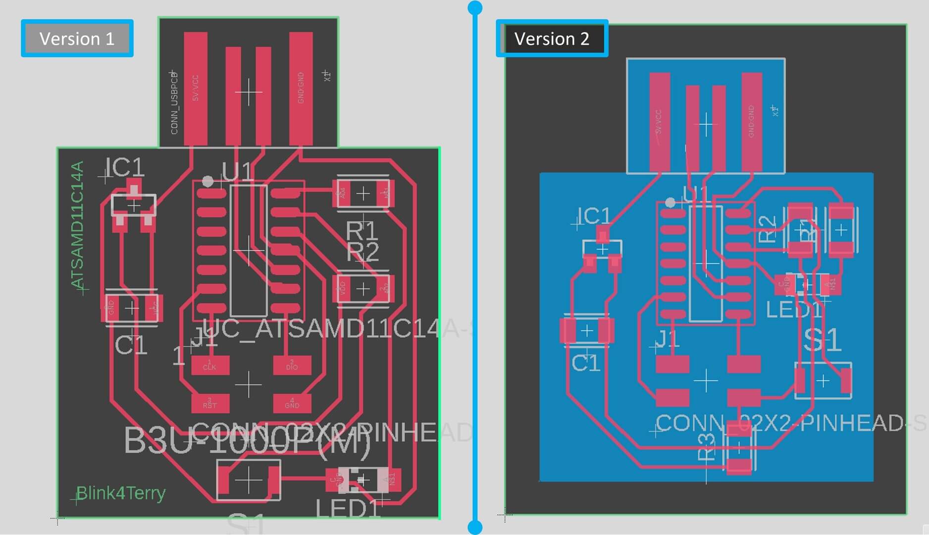
I’ve made two version, and of course the sencond one is better!
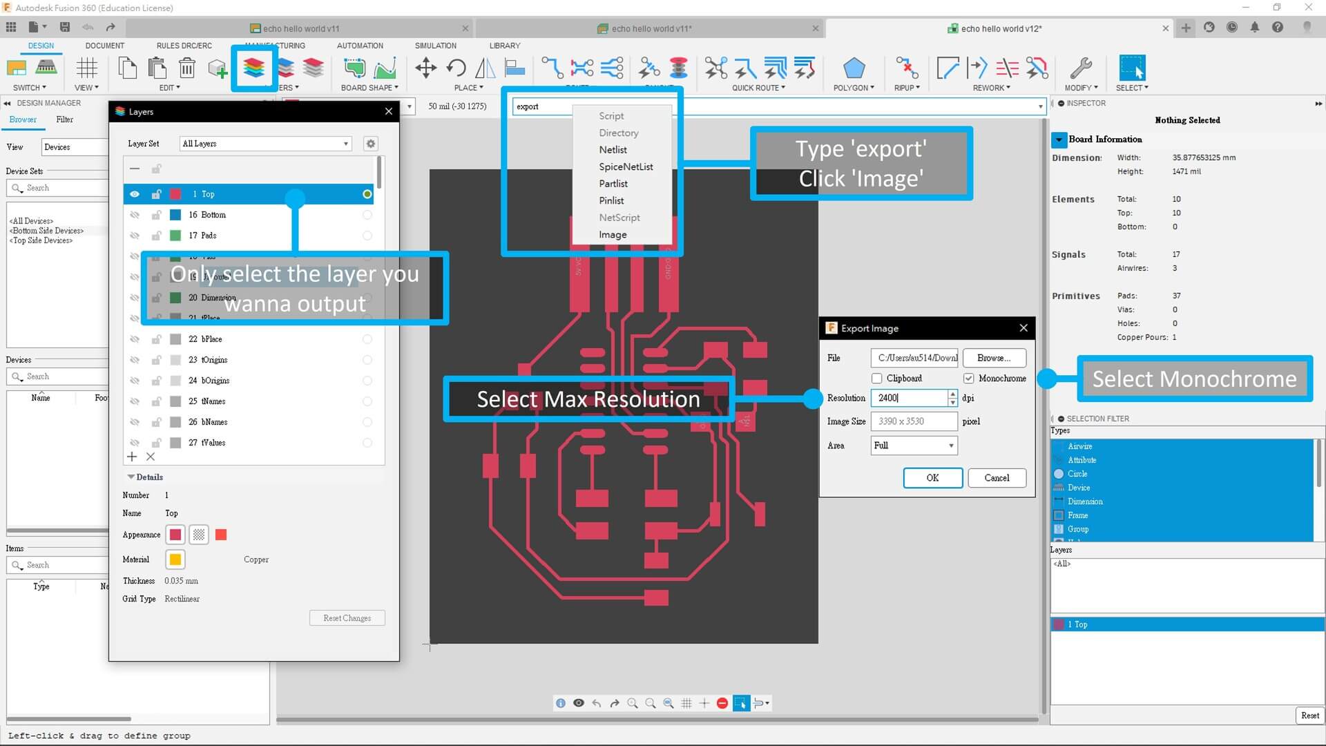
After all design done, you need to export the PNG for milling. By unselect all layers except of the top layer, then type ‘export’ in the command line and click ‘Image’. Then select monochrome and max resolution which is 2400 dpi. After finished the traces, you need to do the same for interior.
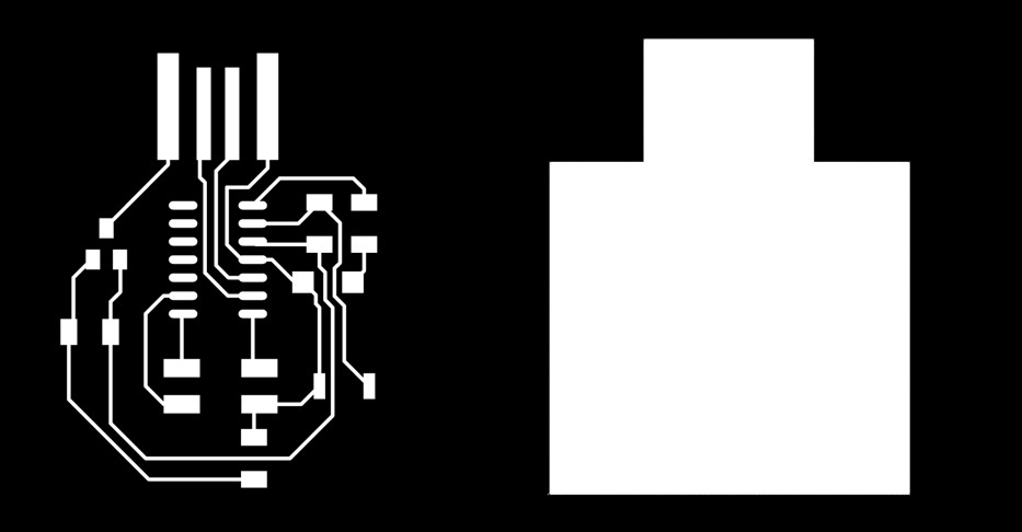
Results:
Left: traces | Right: interior
Milling the PCB board
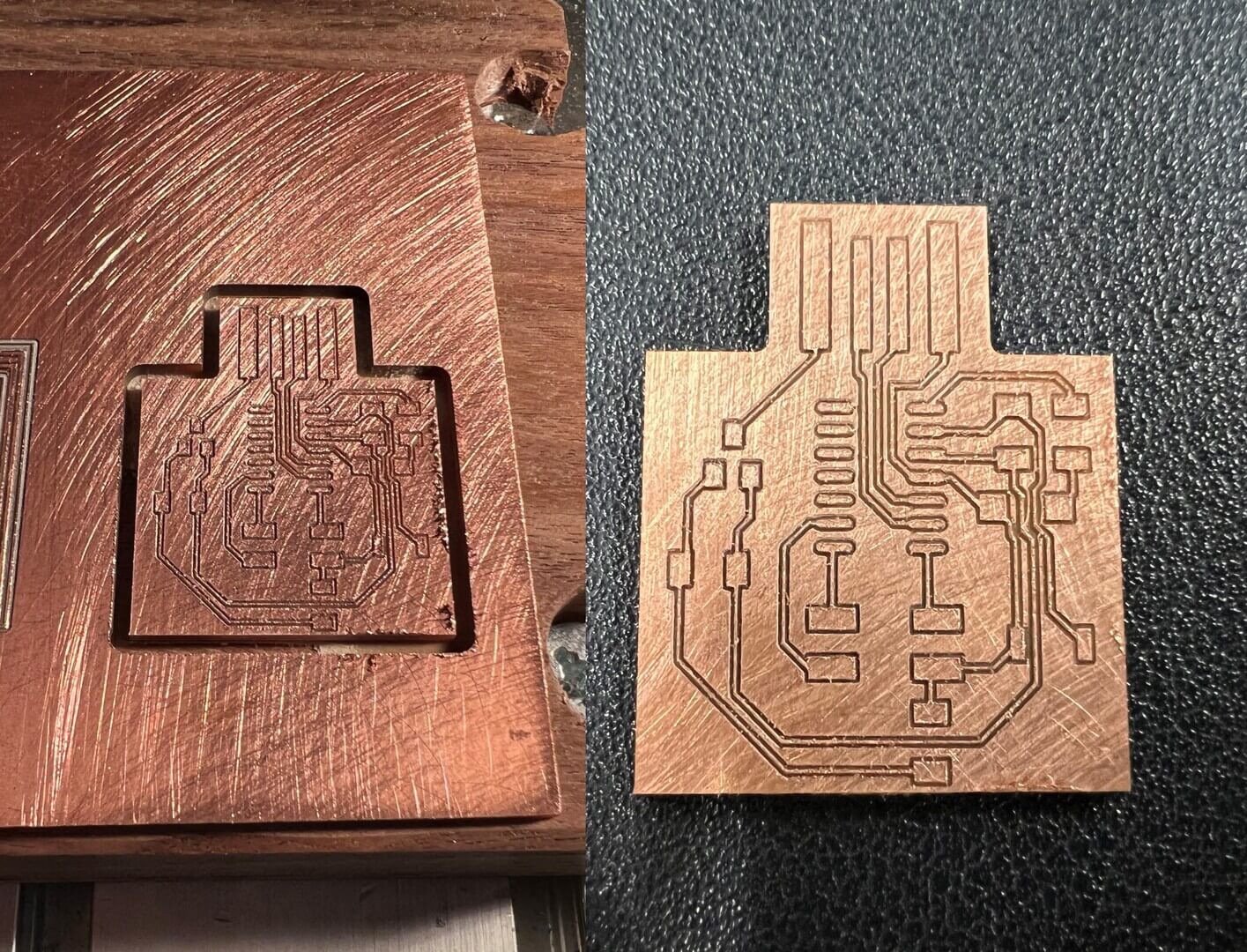
Same as week 5, I used Roland Modela Pro MDX-500 for milling the PCB board. Although it is not suitable for mass production, it is convenient for rapid prototyping and is more environmentally friendly.
I used Mods to generate .nc file and EdytorNC for communication.
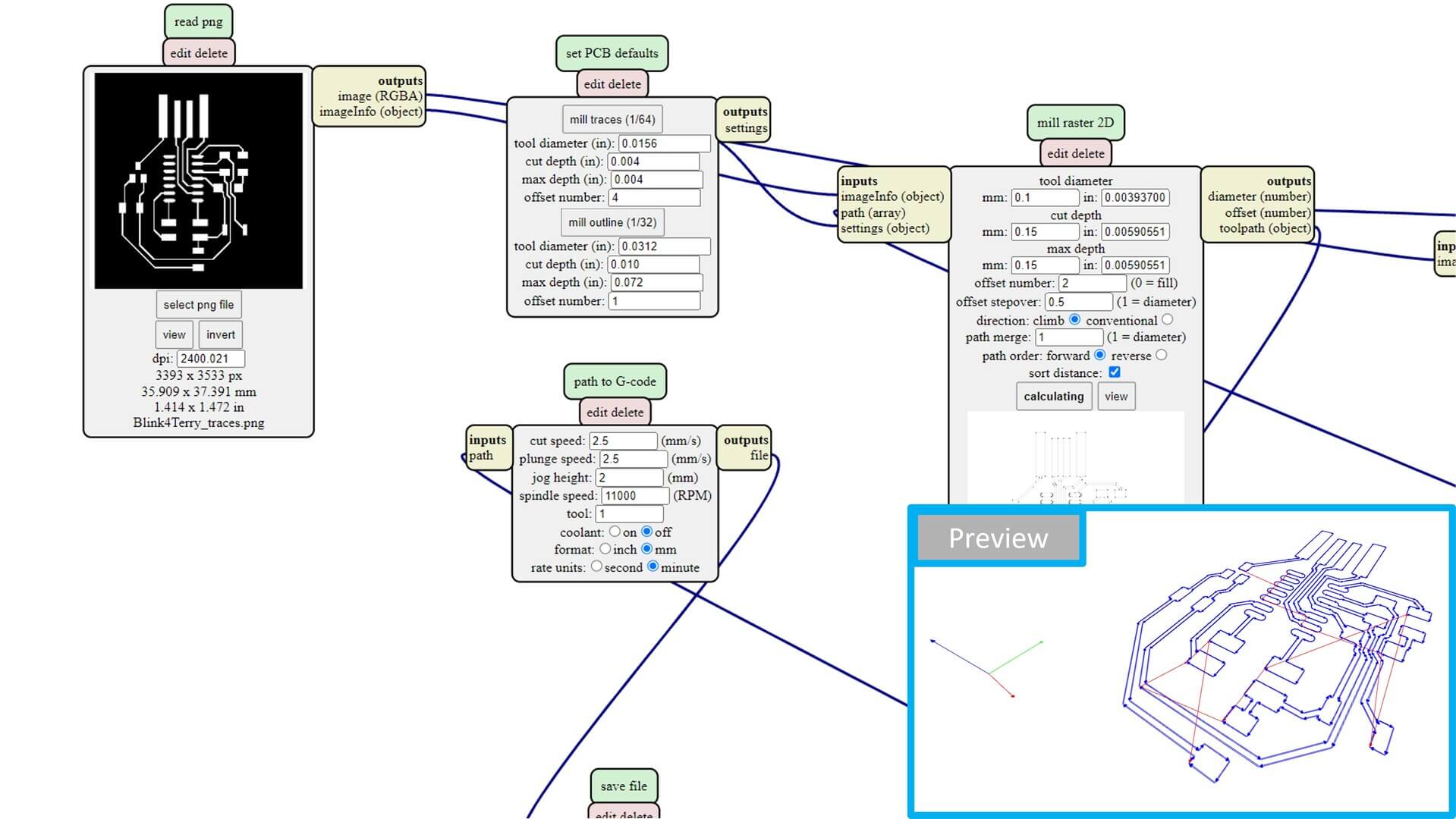
I used 0.1mm 10 degree V-bit for milling the traces, and 1.5mm contouring bit for milling the interior. 0.15mm cut depth. Offset for 2 time. 2.5 mm/s for cut and plunge speed.
| Type | |
|---|---|
| Tool for traces | 0.1mm 10 degree V-bit |
| Tool for interior | 1.5mm contouring bit |
| Cut depth | 0.15mm |
| Offset number | 2 |
| Cut speed | 2.5 mm/s |
| Plunge speed | 2.5 mm/s |
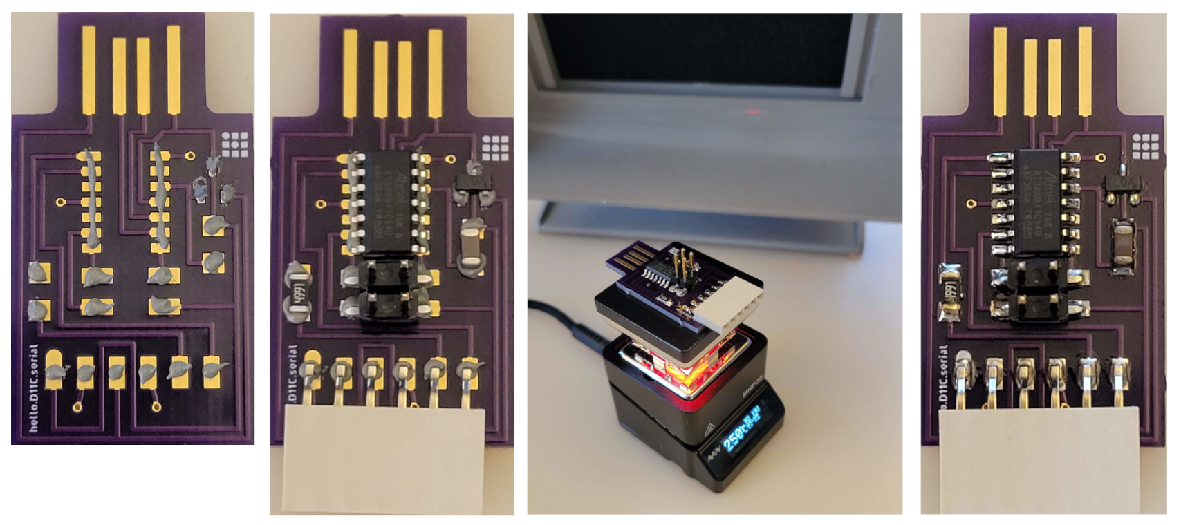
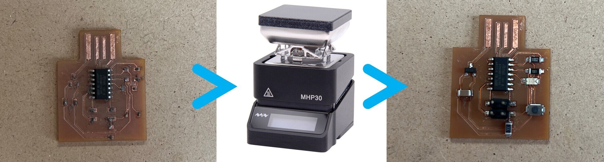
Soldering
Then I take the PCB board and all my Components back home for soldering.
Removed all the useless copper in case of short circuit.
Then I used the lead-free paste and hot plate for solder my PCB board.
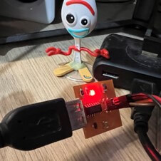
Programming
Then I plug it in to my PC.
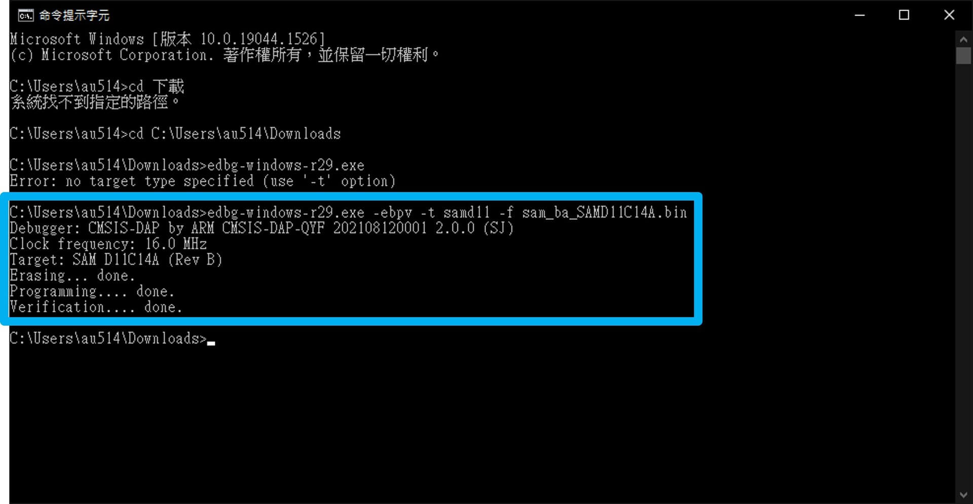
Downloaded the edbg.exe and sam_ba_Generic_D11C14A_SAMD11C14A.bin file, then I’ve install the .bin file into the chip by using this command in terminal.
In your CMD, you can use
cd <dir>to change directory,mkdir <name>to make directory,lsto list what files are in the current directory.
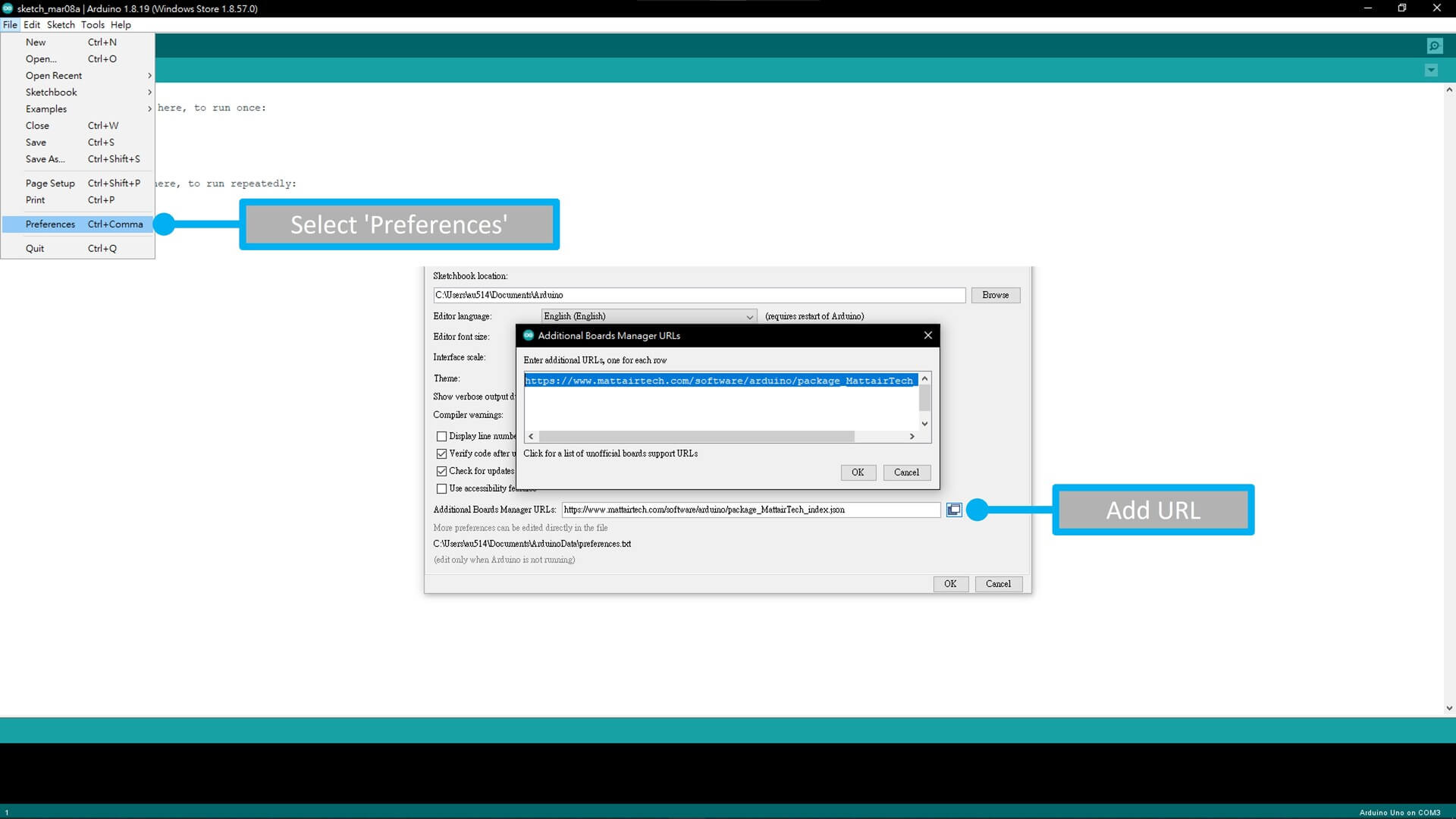
After then, I’ve went into the preferences and add a URL to letting you to install the board data and program with it.
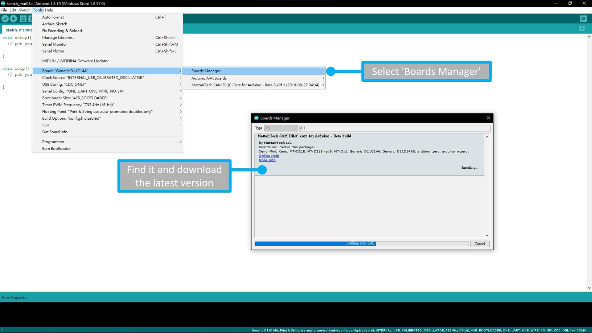
Then, in the ‘Boards Manager’, I’ve installed the package which included SAM D11C core board for Arduino.
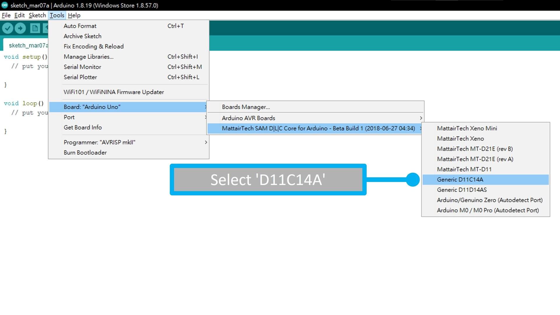
Then, select the D11C14A and started to program it :)
So I’ve tried to porgram it without using the button first, After it works, I added the button in the codes.
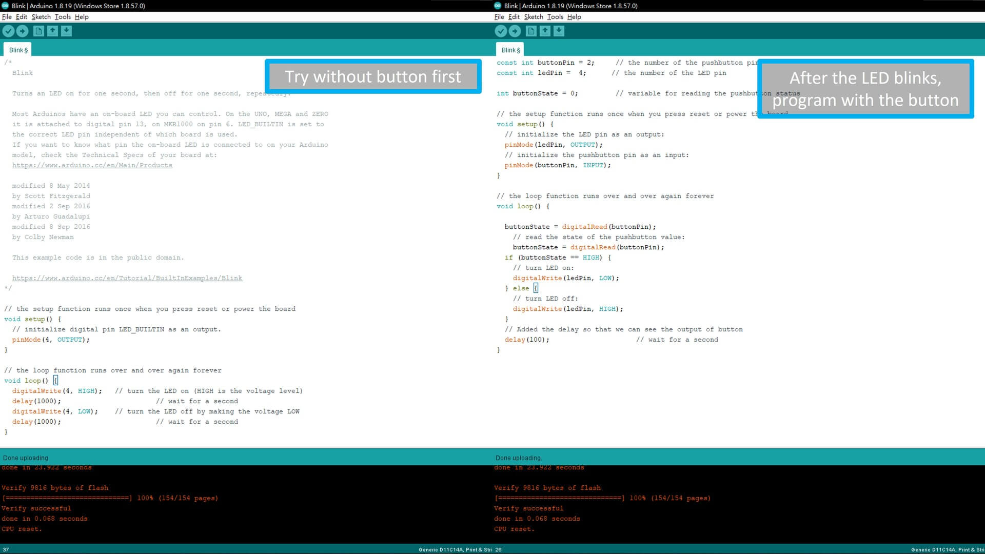
And here is the results. It blinks!
I can control the LED!

Conclusion
After this week, I’ve learned how to make a schematic document, design a PCB board, then install the firmware of arduino and program it using Arduino IDE.
Downloads
Blink4Terry f3z design file - Google Drive
Blink4Terry (New) f3z design file - Google Drive
Blink4Terry (New) trace & outline png file - .zip