Electronics Design
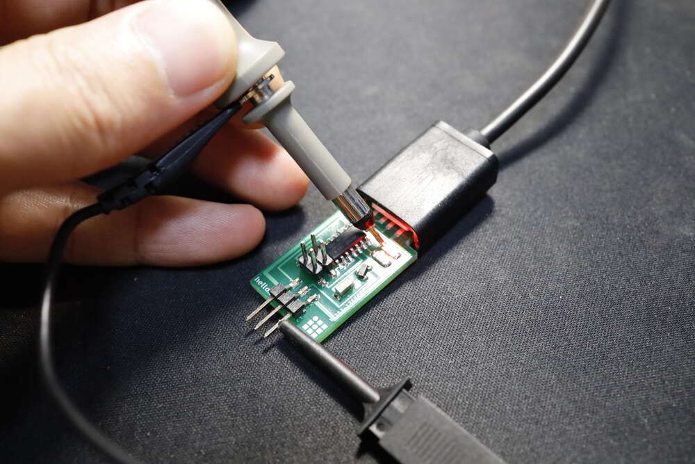
This week, our group used the Digital Multimeter(DMM) and Digital Oscilloscope to observe the operation of a circuit board with SAMD11C.
Group Assignment
- [✓] Use the test equipment to observe the operation of a microcontroller circuit board
- Documented by Darren Chan
Equipments
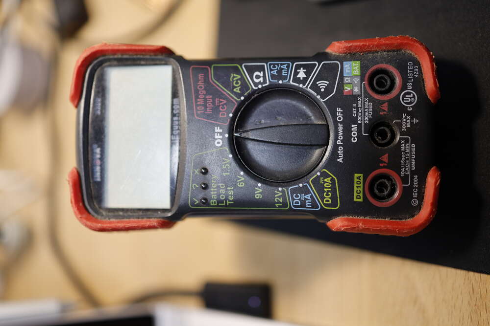
- AC/DC Voltage Measurement
- Resistance Measurement
- Diode Test
- Continuity Test
- AC/DC Current Measurement
- Battery Test
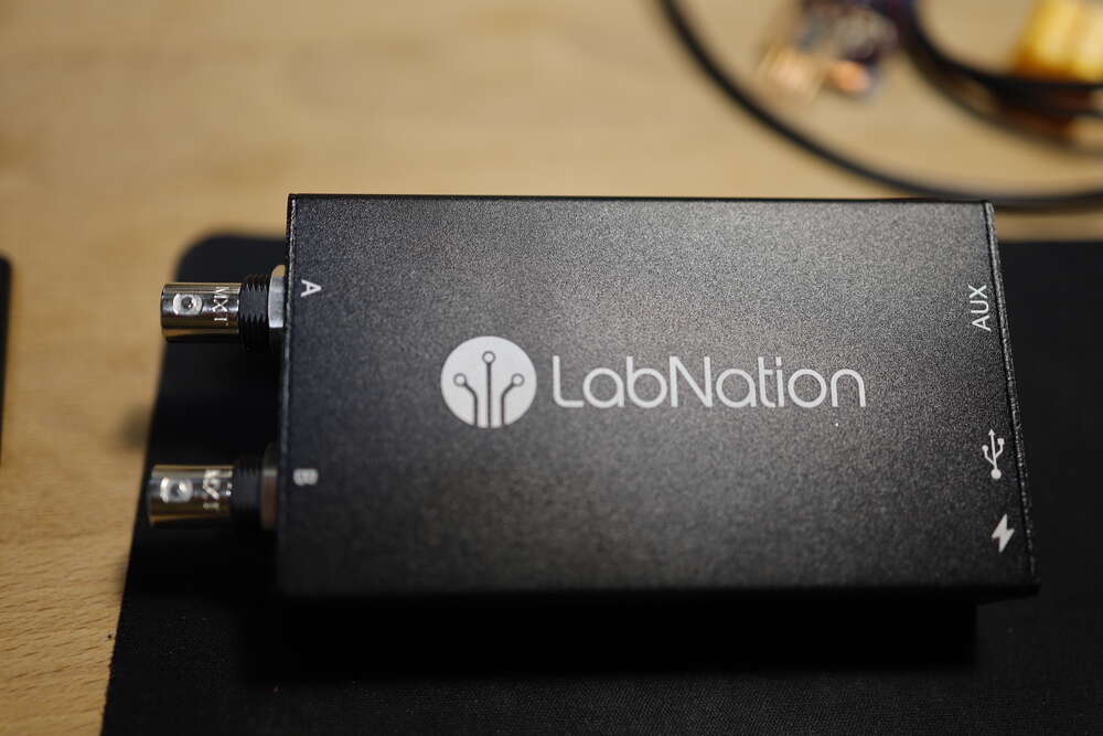
- 2 Oscilloscope channels @ 100MS/s sample rate
- 8CH Logic Analyzer
- 1CH Analog + 4CH Digital Wave Generator
- App Platform: Windows, Linux, OS X, Android, iOS
Results
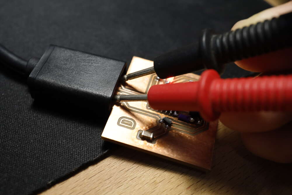
We tested Darren’s IO board, hello.servo.D11C and a USB-TTL adapter. We checked:
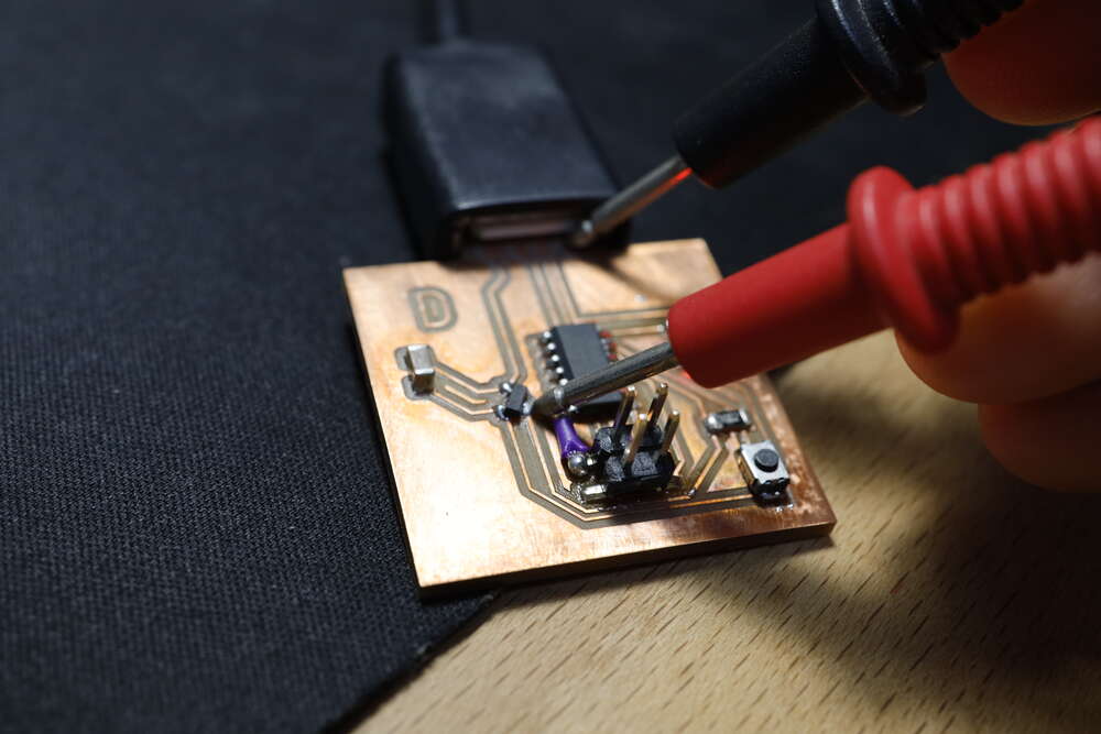
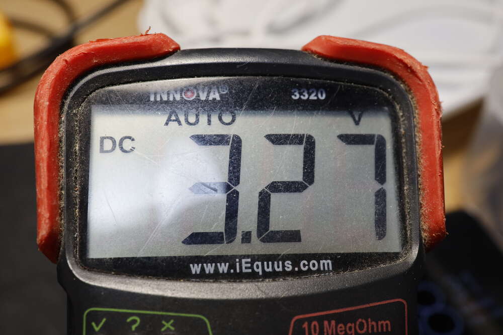
- the input voltage of the USB
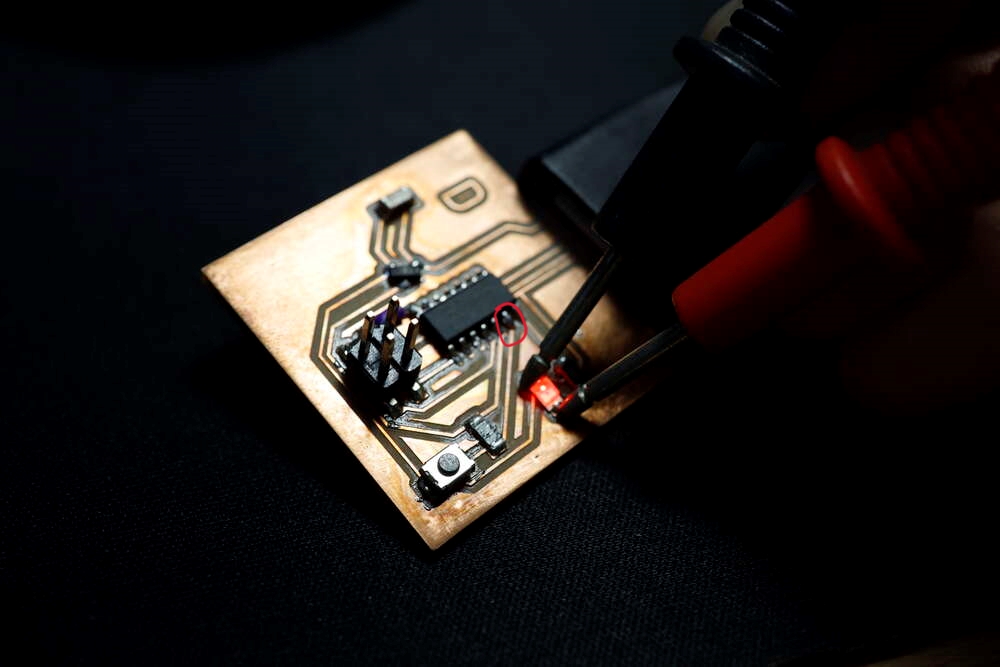
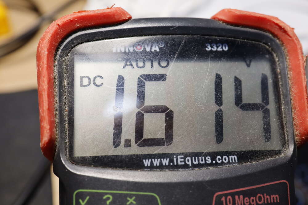
- the regulated voltage of the IO board
- the voltage delivered to the P02 when the button being pressed and released
- the waveform of the LED when it’s blinking
- the waveform of the LED when it’s fading
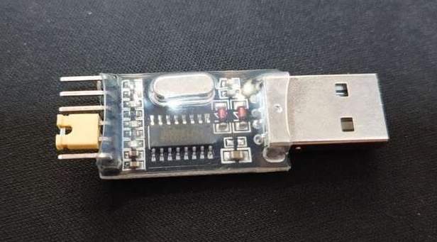
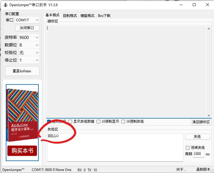
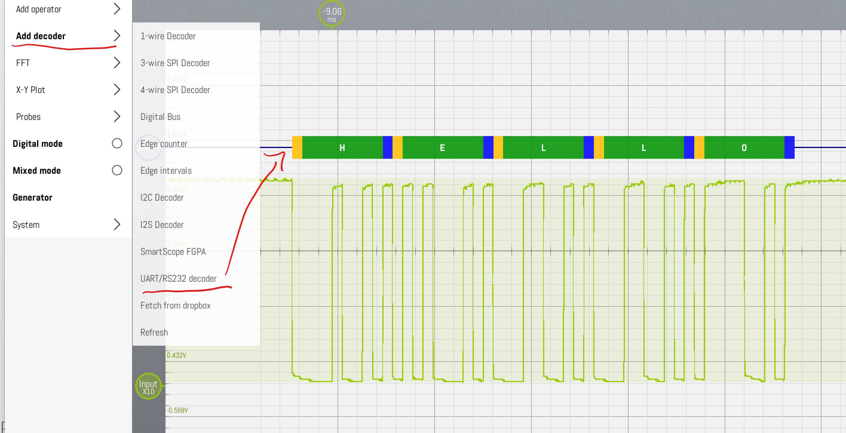
- the encoded signal when a usb-ttl adapter
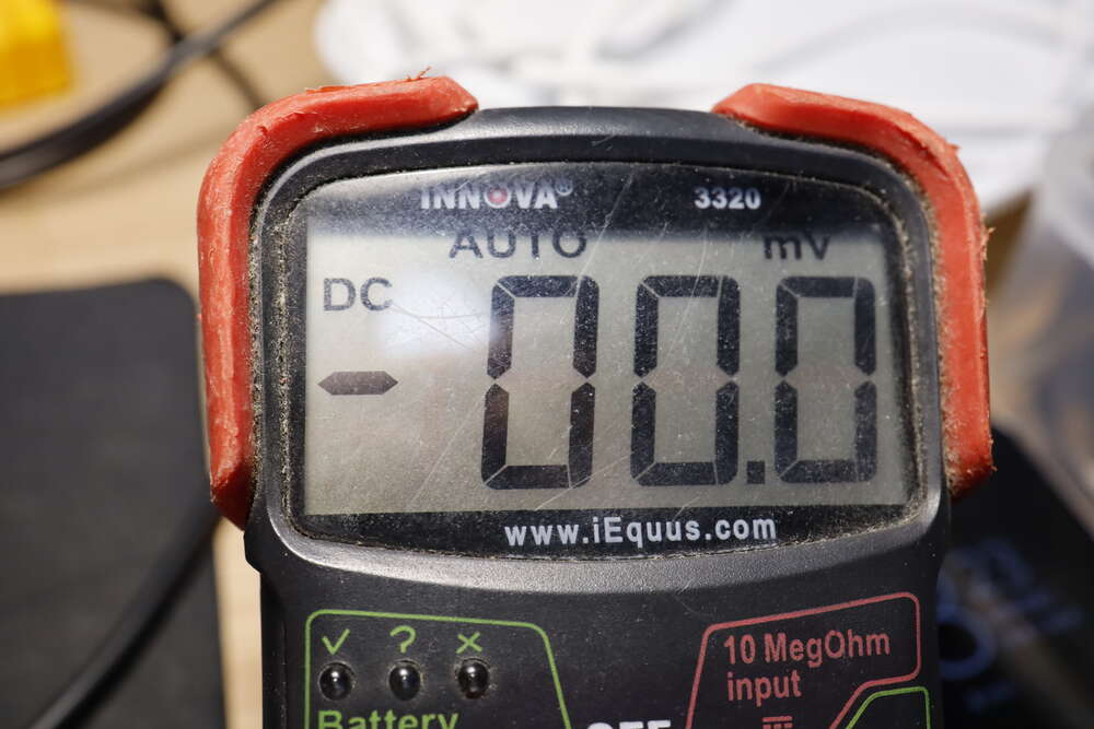
input voltage of the USB
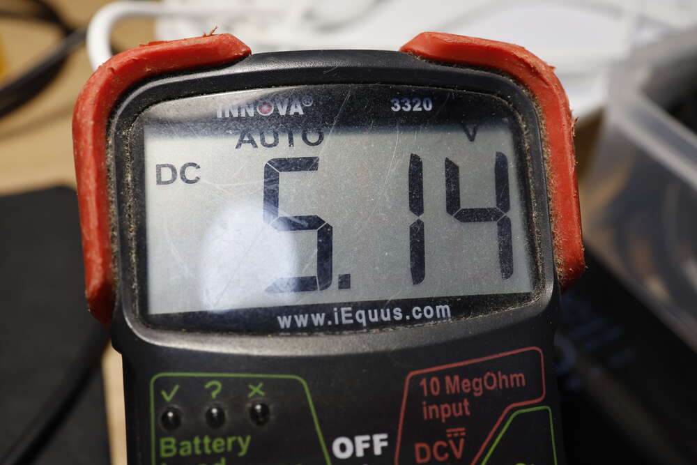
the regulated voltage of the IO board
the voltage delivered to the P02 when the button being pressed and released
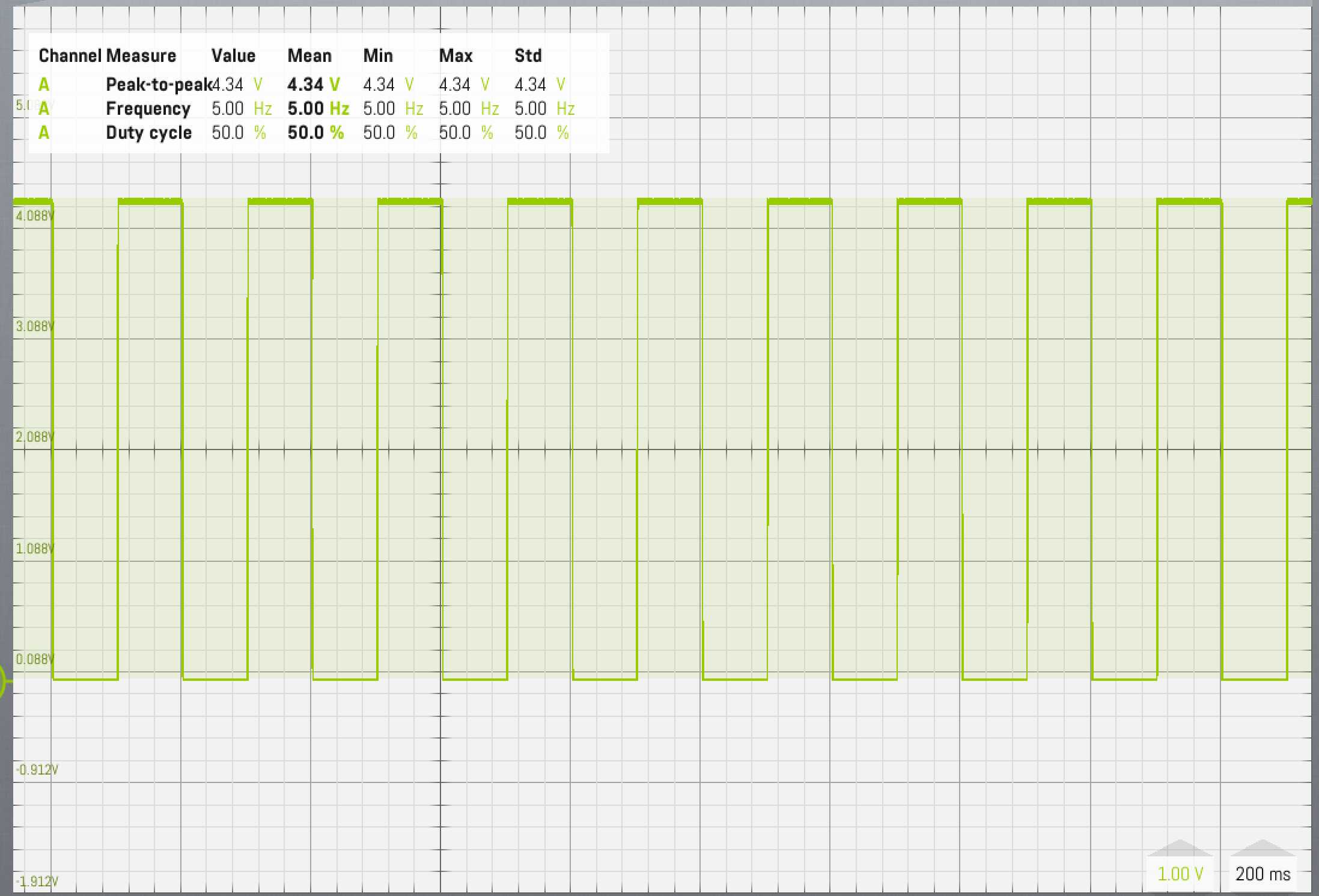
the waveform of the LED when it’s blinking
the waveform of the LED when it’s fading
the encoded signal of a usb-ttl adapter
Last update:
March 29, 2022