Final Project
Final project requirements
What does it do
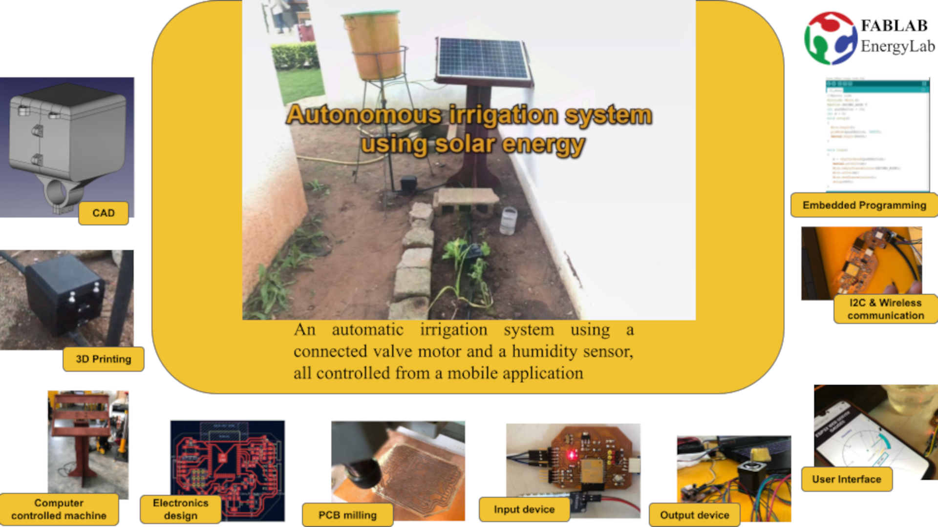
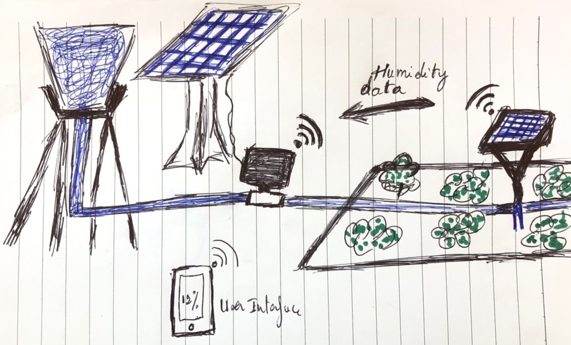
The final project is an autonomous irrigation system powered by solar energy. It is composed of a smart autonomous valve that communicates remotely via wifi with a soil moisture sensor. The moisture sensor sends in real time the soil moisture information to the valve and when the moisture reaches a threshold justifying a lack of moisture, the valve automatically opens for a set time to irrigate the soil. In addition, we have a user interface that allows you to monitor soil moisture in real time.
Who has done what beforehand
After a long search through the fab academy project database, one of the projects that came closest to what I want to do is William Whitaker’s project that did the fab academy in 2016. His project called Wireless Irrigation is a system consisting of a solenoid valve and a moisture sensor that communicate with each other wirelessly from two nRF24L01 wifi modules.
Here is the page of his final project

What I designed
For this project there are five main elements the were designed. They are:
- Solar powered soil moisture data collection and transmission system
- User interface
- The valve automation and humidity data reception system
- The solar power system support for the valve
Bill of Materials
| Description | Quantity | Source | Cost | Link |
|---|---|---|---|---|
| Nema17 | 1 | Amazon | $8.33 | Link |
| DRV8825 Stepper Motor Driver Module | 1 | Amazon | $3.7 | Link |
| 18650 rechargeable lithium battery | 1 | Aliexpress | $5.11 | Link |
| Moisture Water Sensor | 1 | Amazon | $8.53 | Link |
| Espressif ESP32-WROOM-32E | 2 | Amazon | $16 | Link |
| TP4056 Battery Charger Board Charging | 1 | Amazon | $1.7 | Link |
| Drip kit | 1 | LEWATT | $40,10 | Link |
| Ball Valve 15x21 | 1 | LEWATT | $6,90 | Link |
| Threaded end | 1 | LEWATT | $0,59 | Link |
| Rechargeable battery 12V 9AH | 1 | LEWATT | $31,36 | Link |
| ATTiny 412 | 1 | DIGI-KEY | $0.64 | Link |
| 3.3V 1A Linear regulator SOT223 | 2 | DIGI-KEY | $1.08 | Link |
| 5V 1A Linear regulator SOT223 | 1 | DIGI-KEY | $1.05 | Link |
| Switch Slide AYZ0102AGRLC 100MA 12V | 2 | DIGI-KEY | $2.24 | Link |
| Limit Switch | 1 | AliExpress | $4.80 | Link |
| Button Tactile B3SN-3112P 0.05A 24V | 2 | DIGI-KEY | $2.14 | Link |
| Red Led 1206 SMD | 2 | DIGI-KEY | $0.80 | Link |
| Blue Led 1206 SMD | 2 | DIGI-KEY | $0.46 | Link |
| Diode Schotty 40v 2A 1206 | 1 | DIGI-KEY | $0.48 | Link |
| 0.1uF capacitor 1206 | 2 | DIGI-KEY | $0.70 | Link |
| 10uF capacitor 1206 | 3 | DIGI-KEY | $1,05 | Link |
| 1uF capacitor 1206 | 3 | DIGI-KEY | $0.81 | Link |
| 10 Kohm Resistor 1206 | 8 | DIGI-KEY | $0.80 | Link |
| 4.99 Kohm Resistor 1206 | 6 | DIGI-KEY | $0.60 | Link |
| 0 ohm Resistor 1206 | 14 | DIGI-KEY | $1.4 | Link |
| 1x2 Female PinHeader SMD | 3 | DIGI-KEY | $1.53 | Link |
| 1x4 Female PinHeader SMD | 1 | DIGI-KEY | $0.79 | Link |
| Male PinHeader SMD | 1 | DIGI-KEY | $4.23 | Link |
| FR1 Copper Clad PCB Board | 1 | Carbide 3D | $ 10.00 | Link |
| Total = $150 |
The parts and systems that have been made
As mentioned the systems described are as follows:
- Solar powered soil moisture data collection and transmission system
- User interface
- The valve automation and humidity data reception system
- The solar power system and the water tank support for the valve
In the following subsections I will provide the details on the parts and systems and their functions.
1. Solar powered soil moisture data collection and transmission system
For this system, I started by designing the electronic board that receives the data from a soil moisture sensor and transfers it by wifi thanks to the ESP32 module.
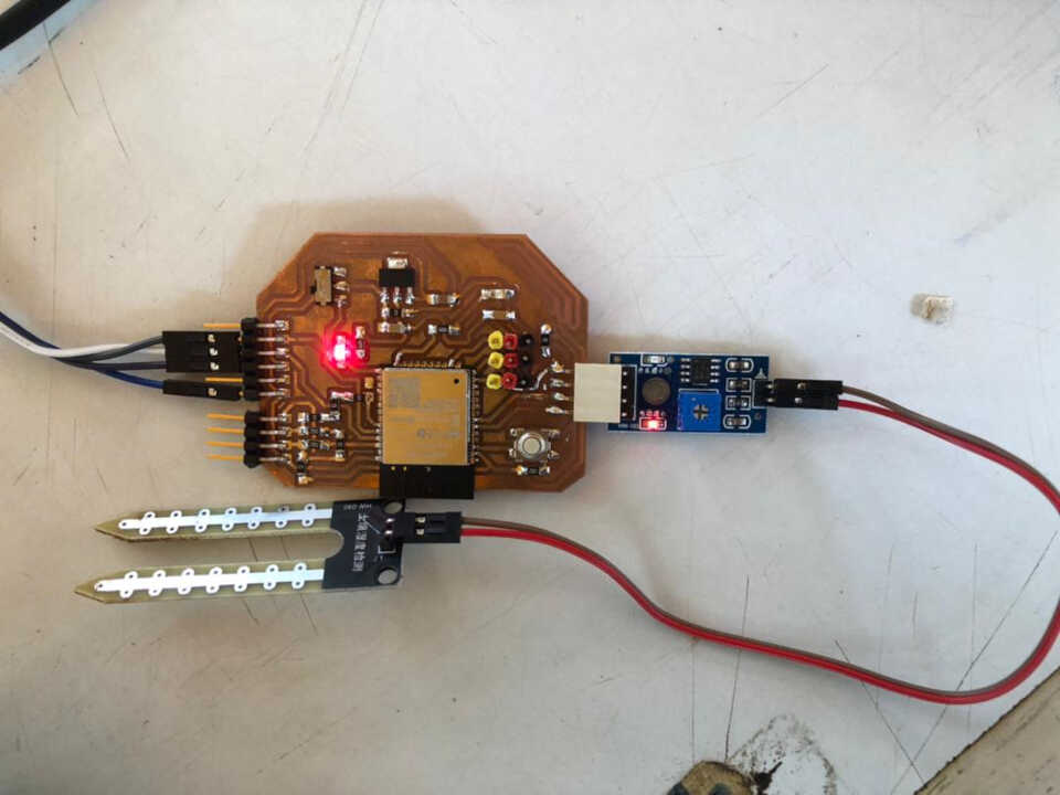
After designing the electronic board it was important to look at the question of solar power supply in order to know the number of solar plates needed for the device before being able to model the box.
For the solar power supply we have a rechargeable lithium battery, the TP4056 module for charging the battery and a small solar plate with a size of 60x60. For a good charge of the battery, the TP4056 module needs an input voltage of 5V.
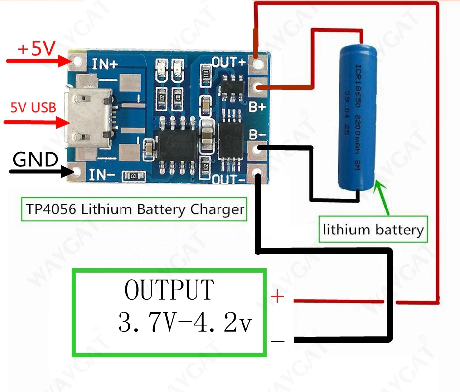
The measurement of the electrical voltage of a plate is about 1,5V.
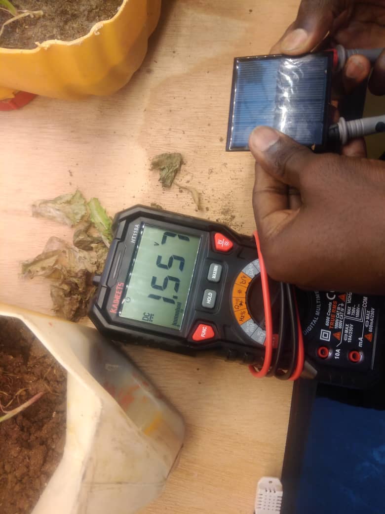
It is thus necessary at least 4 solar plates to provide enough energy for the load of the battery.
Now that we know the number of solar plates to use, we can design the device housing.
2. User interface
The user interface has been programmed in HTML, CSS and JAVASCRIPT and hosted on the ESP32 board. The interface is accessed through the IP address of the ESP32.
The interface displays in real time the moisture value measured by the soil moisture sensor.
The html,css,javascript code and ESP32 code can be found at this link at should be kept together in the same folder.
3. The valve automation and humidity data reception system
For the development of the autonomous valve, two electronic boards have been produced.
The first board is the board that controls the stepper motor. It has an I2C input/output to communicate with the second board of the valve.
The motor board is programmed to receive essentially two pieces of information, namely information about the direction of rotation of the motor and information about whether the motor has stopped or started. The arduino code for the motor board can be found at this link.
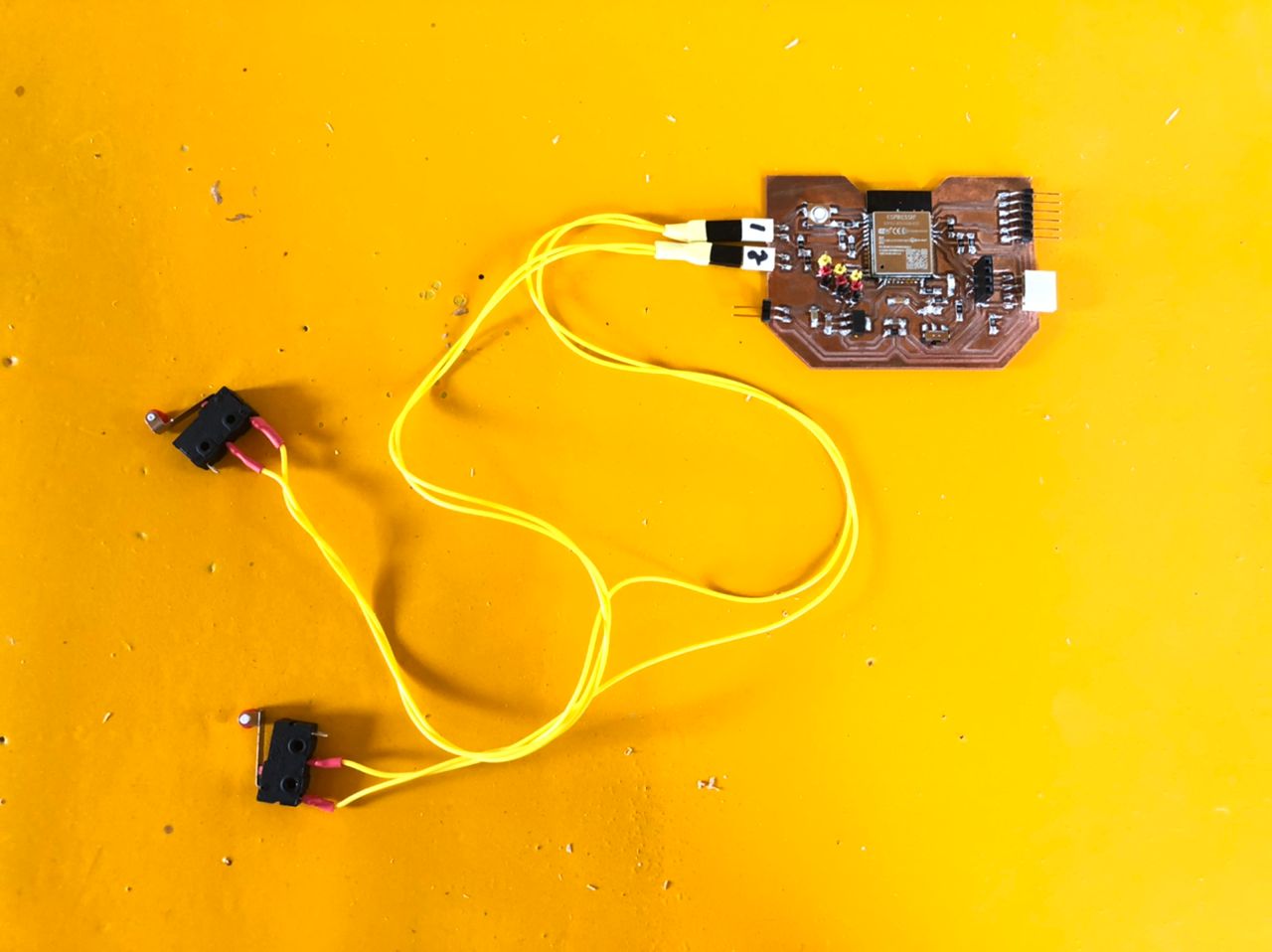
The second electronic board produced for the valve allows the system to:
- Communicate with the humidity sensor board via WIFI
- Control the direction of rotation, stop or start of the motor, communicating via I2C with the stepper motor control board
- Sensing the opening and closing positions of the motors from two limit switches
The board has been designed taking into account the above mentioned needs
Now the two boards of the valve system can communicate with each other. In order to test the interaction between the two boards of the valve system, an Arduino code has been written.
The program of the board with the ep32 module will be the master and the stepper motor board will be the slave. In the master program, the master communicates 4 information from the two limit switches.
- Limit switch 1 sends the information of its state which is 0 or 1 which will be used to control the direction of rotation of the motor.
- Limit switch 2 sends the information of its state 0 or 1 which will be used to control the stop or start of the motor.
You will find here the arduino code for the master board.
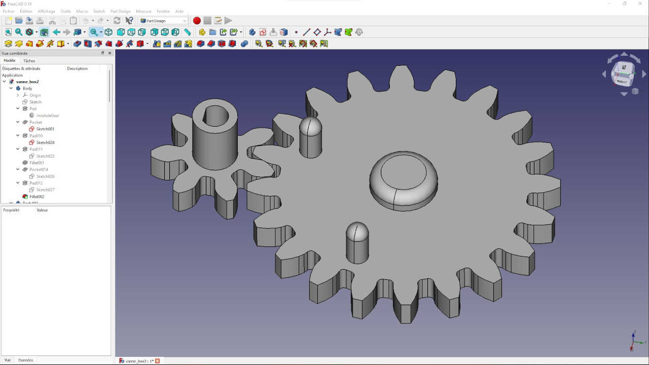
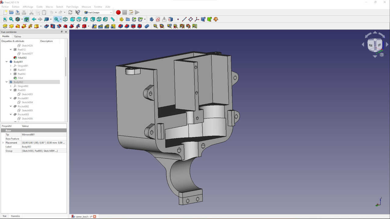
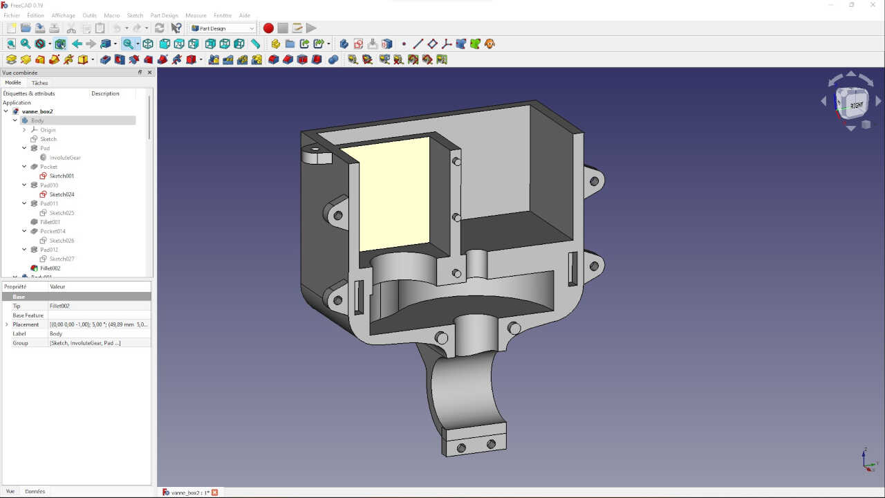
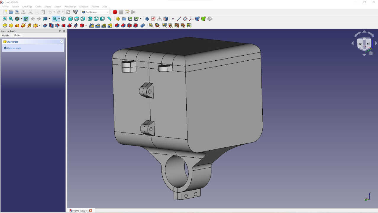
After designing and operating the electronic boards of the system, we design the mechanical system that will allow the motor to have enough force to open or close the valve.
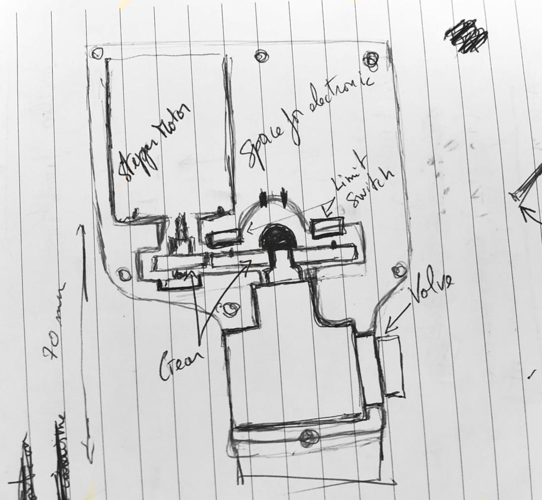
After having finished with the mechanical system we move on to the making of the device housing
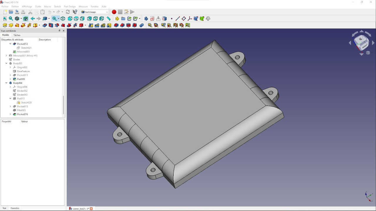
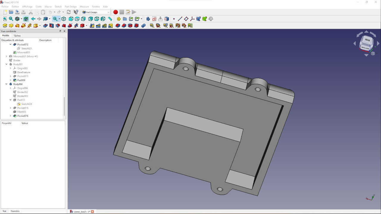
After finishing the printing of the box, we install the elements of the device inside the box to perform the functional test of the autonomous valve.
For the stand-alone valve test, the valve’s esp32 board has been programmed to receive humidity information from the humidity sensor board via wifi.
When the humidity drops below 30%, the valve’s esp32 board commands the stepper motor board to open the valve for a period of 10 seconds before closing the valve. You will find here the Arduino code of the system operation below.
4. The solar power system and the water tank support for the valve
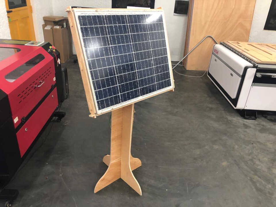
For the solar power supply of the valve, we used a 50 watt solar panel that was already available in our laboratory. It was therefore important to design a support for it.
Thinking about the location of the battery and the charger controller I decided that it was best to mount it on the water tank support that will be used for the project.
While walking around the EnergyLab yard I came across a hand washing device that was no longer in use. I took it to use it as a water tank for the project.
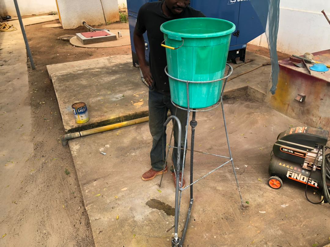
In order to install the battery, charge controller, and self-contained valve, I had to make a few minor modifications to the handwashing device.
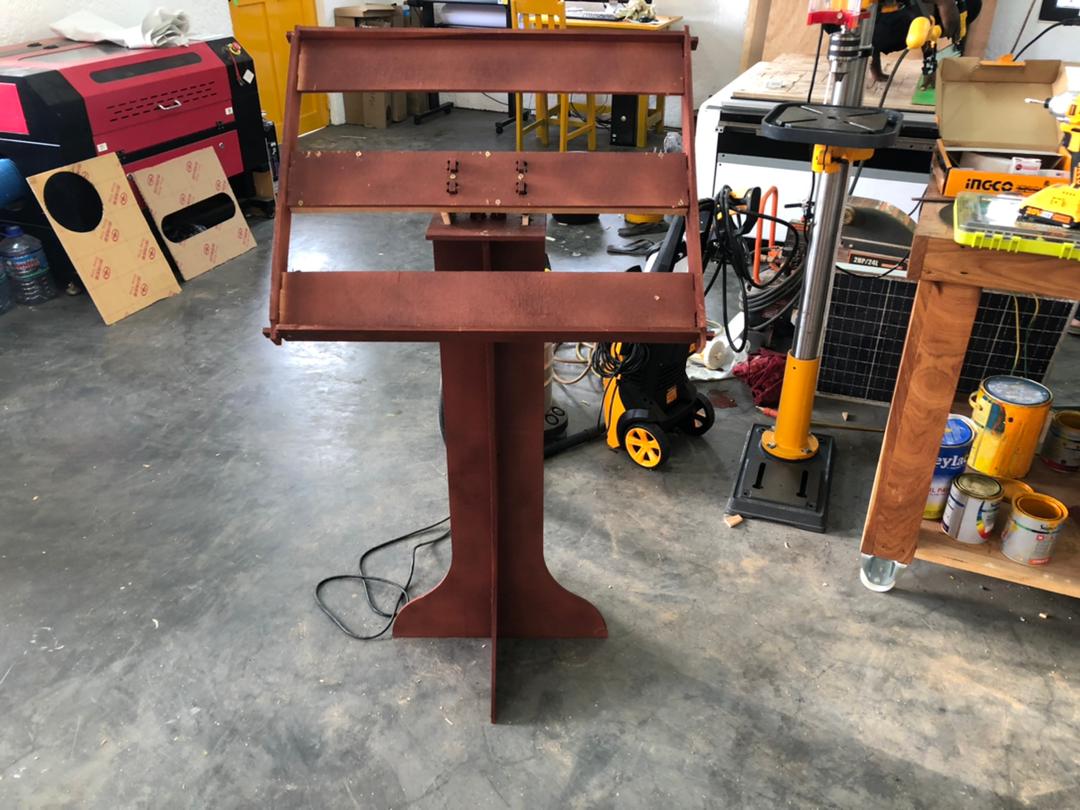
After completing the repair of the supports, we install the self-contained valve in addition to the other elements of the project that must come into play.
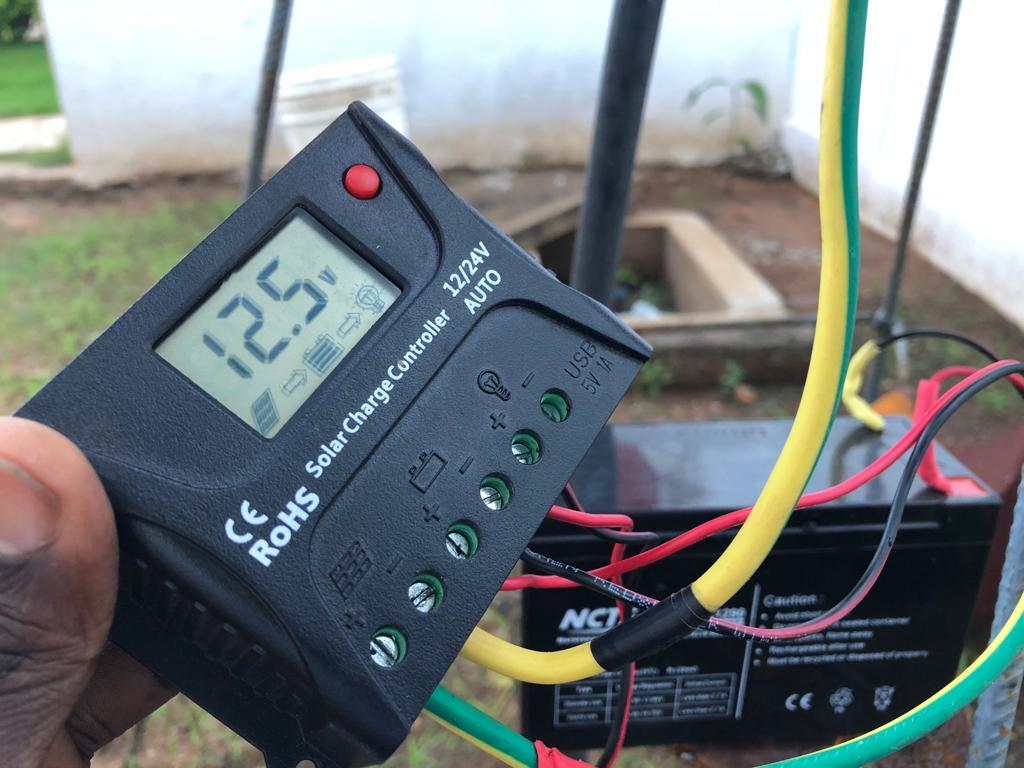
With all the devices in place we finally connect the valve, the battery and the solar panel to the charge controller
Processes used
The processes to be used will be divided by system as follows.
- Solar powered soil moisture data collection and transmission system
This system consists of an electronic board, a battery for power and a box that includes everything. The following processes were used:
- Printed circuit board: Design of the printed circuit board, milling with a small CNC of a copper printed circuit board, soldering.
- Battery holder: 3D design and additive manufacturing by 3D printing.
-
System box: 3D design and additive manufacturing by 3D printing.
-
User interface
The IoT interface was fully realized using programming on the Arduino IDE and HTML code with JavaScript to produce the web page.
- The valve automation and humidity data receiving system.
The valve system is composed of two electronic boards, a mechanical system and a housing that includes
- Circuit Board: Design of the printed circuit, milling with a small CNC of a copper circuit board, soldering.
- the mechanical system: 3D design and additive manufacturing by 3D printing
-
the system box: 3D design and additive manufacturing by 3D printing.
-
The solar power system and the water tank support for the valve
The 2D design and the Wood cutting with large format CNC are used to support the solar panel.
Questions that were answered
After the work completed the following questions were answered:
- Communication protocol for the communication between the two ESP32 modules: wifi
- The percentage of humidity to activate the valve: 30%
- The duration of the valve opening when the humidity percentage is low: I set a short duration of 10 seconds, just to be able to show how the system works in the final presentation video.
- The size of the solar panel to charge a 3.7V battery: Four solar panels of 60 mm x 60 mm each
What worked and didn’t work
Things that worked
- I2C communication between the esp32 board of the valve and the stepper motor board
- Information about the open or closed position of the valve through the two limit switches
- The mechanical system gives the motor enough force to operate the valve.
- The esp32 board of the humidity sensor communicates perfectly with the esp32 board of the valve.
- The four solar plates provide enough energy to charge the battery that powers the humidity sensor
- The solar power supply to the valve
Things that didn’t work
- The user interface should not only display the humidity but also control the irrigation.
- The valve did not fit very well in the housing. I had to put tape all around the valve to create a wedge in the housing.
- The motor board did not work properly at one point because the motor connection pin did not have a good contact with the copper traces.
How it was evaluated
In the applications and implications week I set the following standard of evaluating success:
The project will be considered successful if:
- the actuator device has sufficient force to open and close the valve
- the motorization device works autonomously by communicating via wifi with the humidity sensor.
I would say that overall the project was a success, with the caveat that better results could have been achieved and can be achieved in the future
Implications
I would say that in order to make this product marketable to the African market a siginificant amount of simplification and cost reductions will be necessary. For this course I added all of the bells and whistles in an effort to ensure that I met all the criteria of the Fab Academy program.
Recommendations for simplified versions would include:
- Work to reduce the costs of the combustion chamber
Files
Circuit board
Programs for Ardunio IDE
3D printing
2D filr for large format CNC
My survival in the fabacademy
Before starting the FabAcademy I was already aware that it would be a great challenge for me, not only technically but also because I am a French speaker as I admit that my level of English 6 months ago was catastrophic. This trip in the fabacademy was wonderful, full of learning and discovery but also full of a lot of emotion. I still think about the difficult moments when every week you have to make sure that everything works and that the documents are ready on time. But the worst part is when you don’t understand why your system isn’t working and you spend hours and hours of research before you find the problem. There have been moments of great joy. One of the greatest joys was when we presented our final projects in June, we were very happy after receiving Neil’s appreciation and congratulating us on our work. It was a great joy. I would especially like to thank my instructor Paul Cairns who has been very supportive and encouraging with his explanations, advice and support in learning English. He is a great man with a big heart. Thank you Paul.
The next fabacademy session will be a bigger challenge because this time I will be an instructor. I will give my best for my future students and I hope to do for them as much as my instructor Paul had to do for me.