6. 3D Printing and Scanning
Assignment Overview
Group assignment:
- Test the design rules for your printer(s)
- Document your work and explain what are the limits of your printer(s) (in a group or individually)
Individual assignment:
- Design and 3D print an object (small, few cm3, limited by printer time) that could not be easily made subtractively
- 3D scan an object, try to prepare it for printing (and optionally print it)
Learning outcomes
- Identify the advantages and limitations of 3D printing
- Apply design methods and production processes to show your understanding of 3D printing.
- Demonstrate how scanning technology can be used to digitize object(s)
Have you answered these questions?
- Linked to the group assignment page
- Explained what you learned from testing the 3D printers
- Documented how you designed and made your object and explained why it could not be easily made subtractively
- Documented how you scanned and prepared an object (for 3D printing)
- Included your original design files for 3D printing (both CAD and common format for 3D printing)
- Included your hero shots
In the next section, I will discuss the group assignment and its results.
Group Assigment
The equipement
For the group assignment we had to test the design rules of our printer, document our work, and explain the limits of our printers. Before diving in to the assignment, i will first begin by discussing the equipment.
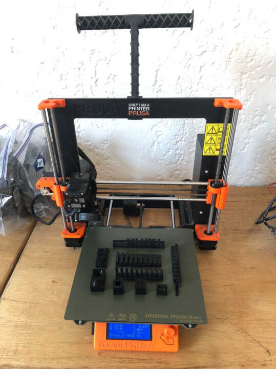
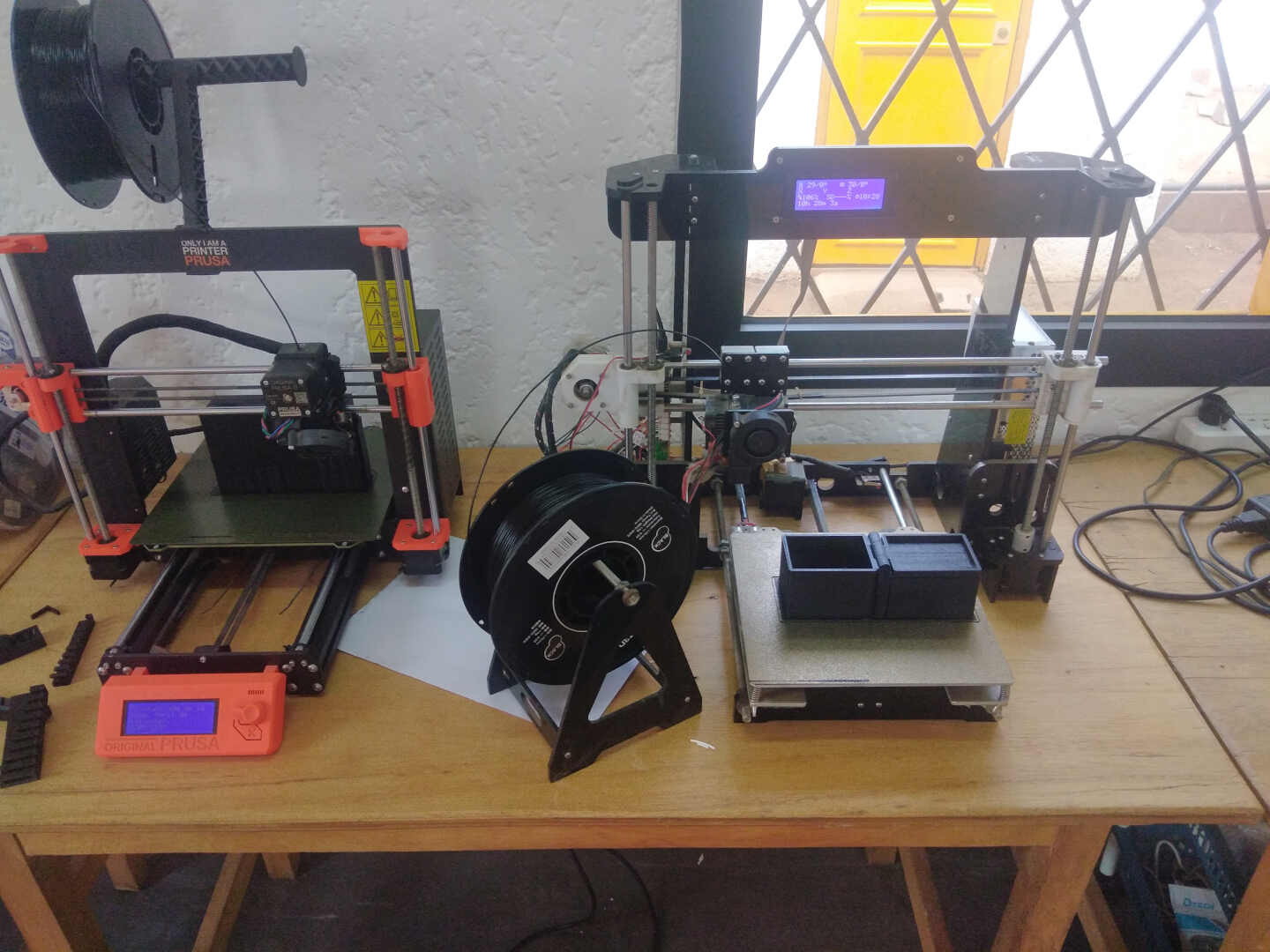
the 3D printer used for this assignment is the Prusa i3 Mk3S which you can see in the image below .
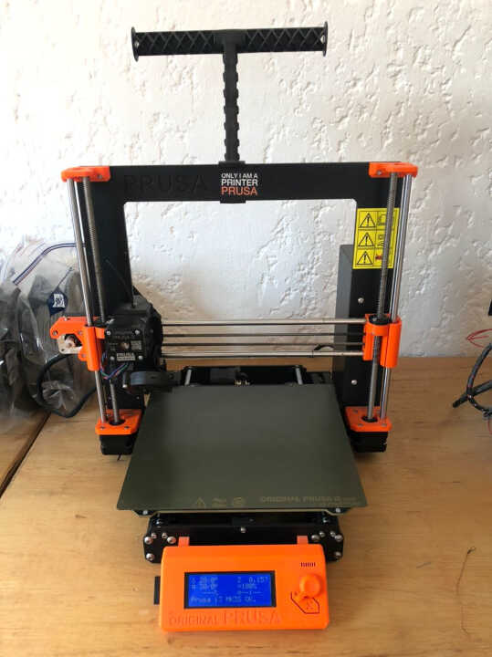
| ORIGINAL PRUSA I3 MK3S SPECS | |
|---|---|
| 3D-Printing Technology | Fused Filament Fabrication (FFF) |
| Materials Supported | PETG, ABS, PLA |
| Number of Print Colors | 1 |
| Number of Extruders | 1 |
| Frame Design | Open |
| Maximum Build Area (HWD) | 9.8 by 8.3 by 8.3 inches |
| Top Print Resolution | 50 microns |
| LCD Screen | Yes |
| Primary Interface(s) | SD Card, USB 2.0 |
| Dimensions (HWD) | 15 by 19.7 by 22 inches |
| Weight | 17 lbs |
The 3D printer software
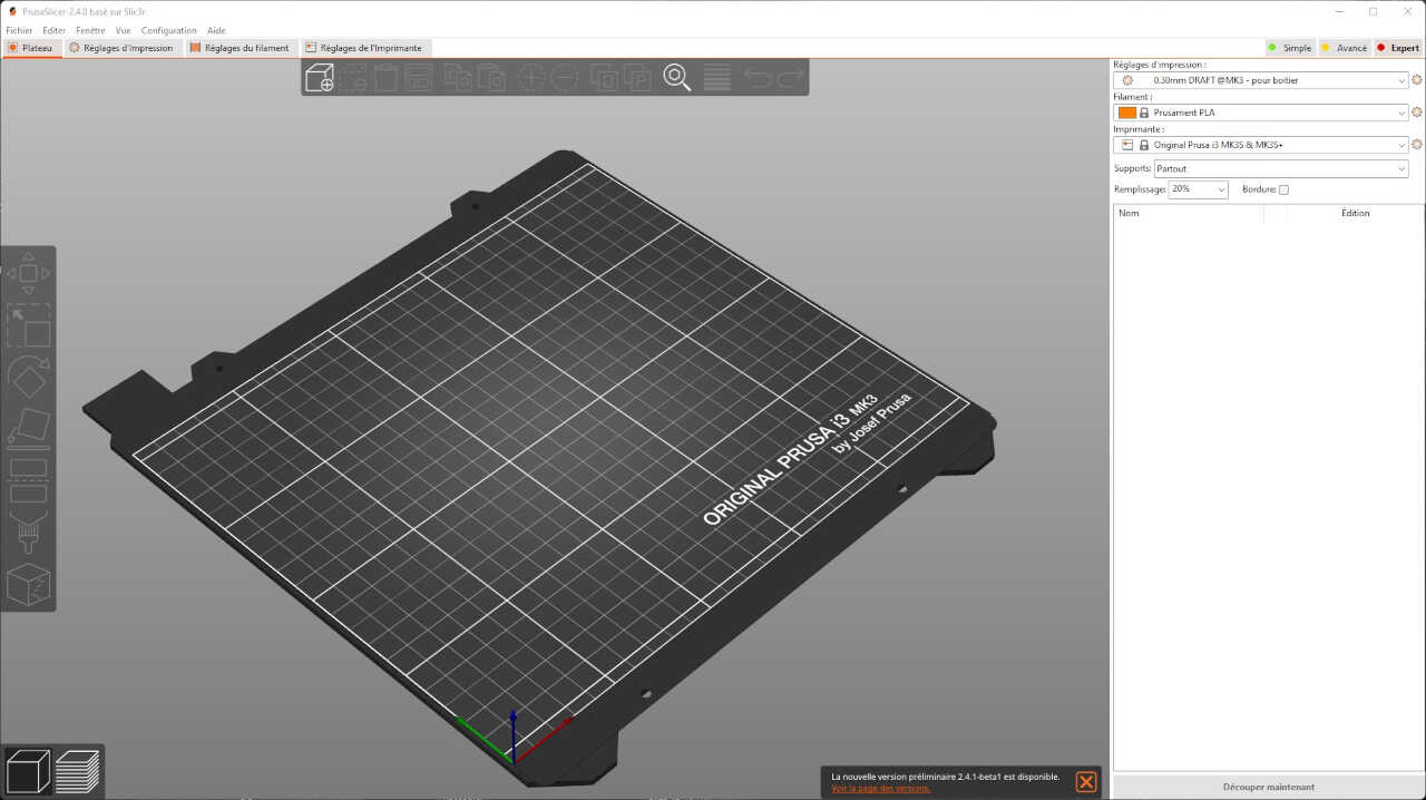
In order for the 3D printer to be able to interpret the 3D files (in .stl format), it will be necessary to use software called a slicer, which will be used to transform the model by slicing/dividing the object into several thin layers superimposed on top of each other, the ones the printer will create. There are several slicer software, but in our case we will use a slicer called PrusaSlicer, which has been developed for Prusa printers.
You can dowload the PrusaSlicer at this link
After we learned how to use the equipment we began the prints for the group assignment.
3D printer test
In order to characterize and learn the limitations of our machine, we chose to download and print the files that were provided on the Fab Academy assignment page.
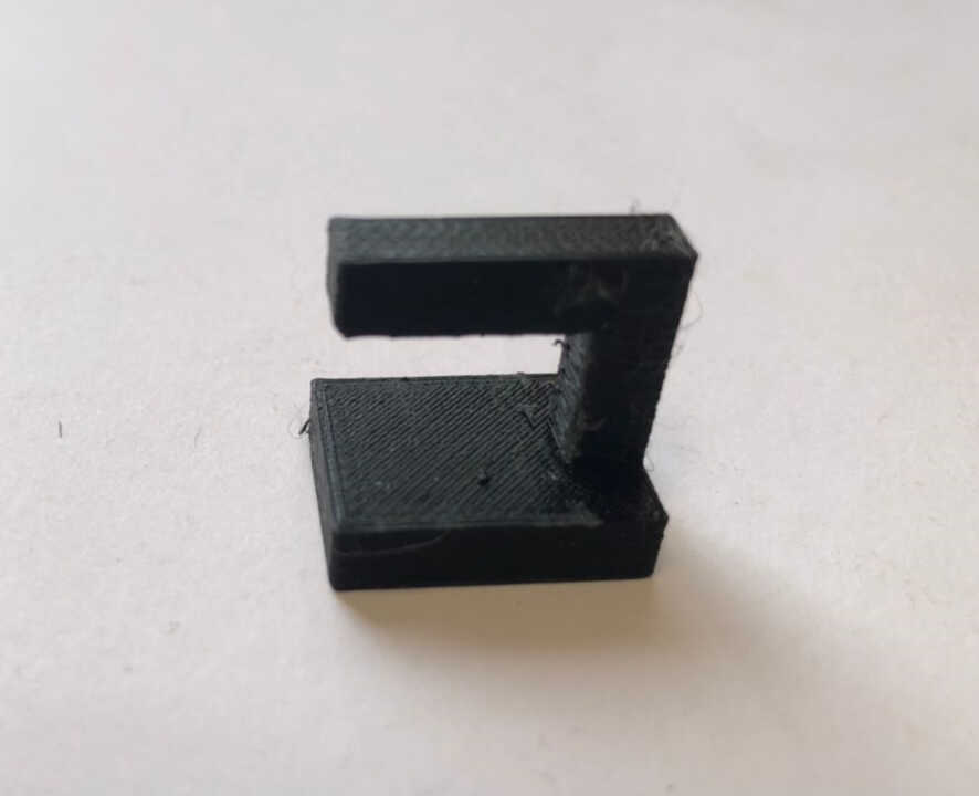
this image below shows the gap clearance capability of our 3D printer. This gives me a list of clearance to choose from if I want to print something with a revolving joint. The clearance started from 0.1mm to 1mm with an increment of 0.1mm. 0.1mm and 0.2mm were not able to move but the rest were moving freely.
![]()
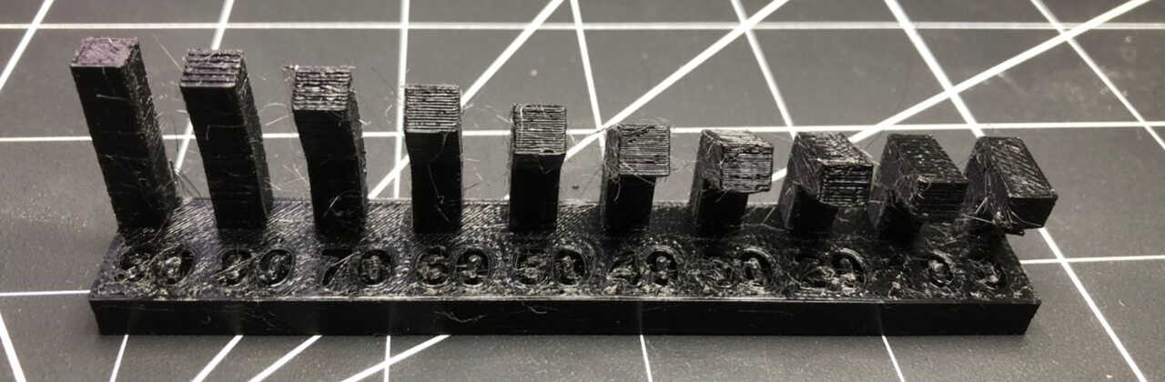
In this test, we printed a piece that had gradually increasing overhangs to test what angle of departure can be used without supports. The results of the test were that we were able to print to an angle of about 20 degrees before having issues with the print results. The photos below indicate the results of these tests:
-Overhang and overhang 2
This test looked at how long of an overhang can be used before the print begins to fail. In this test, overhangs of increasing length are printed and the length at which the print becomes messy is the limit. The results for our printer indicated that the limit is approximately 3 mm of overhang
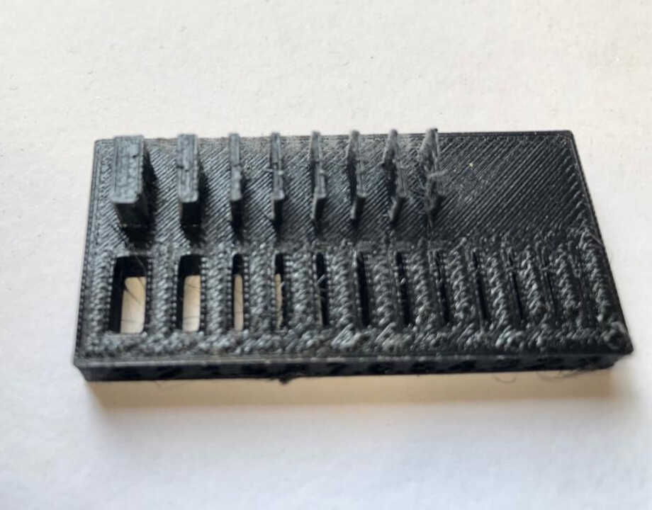
The birdging test evaluates how far your extruder can pul a filament across a gap before drooping or sagging. In this test, the length between two posts is gradually increased. Interestingly, every gap was perfectly bridged
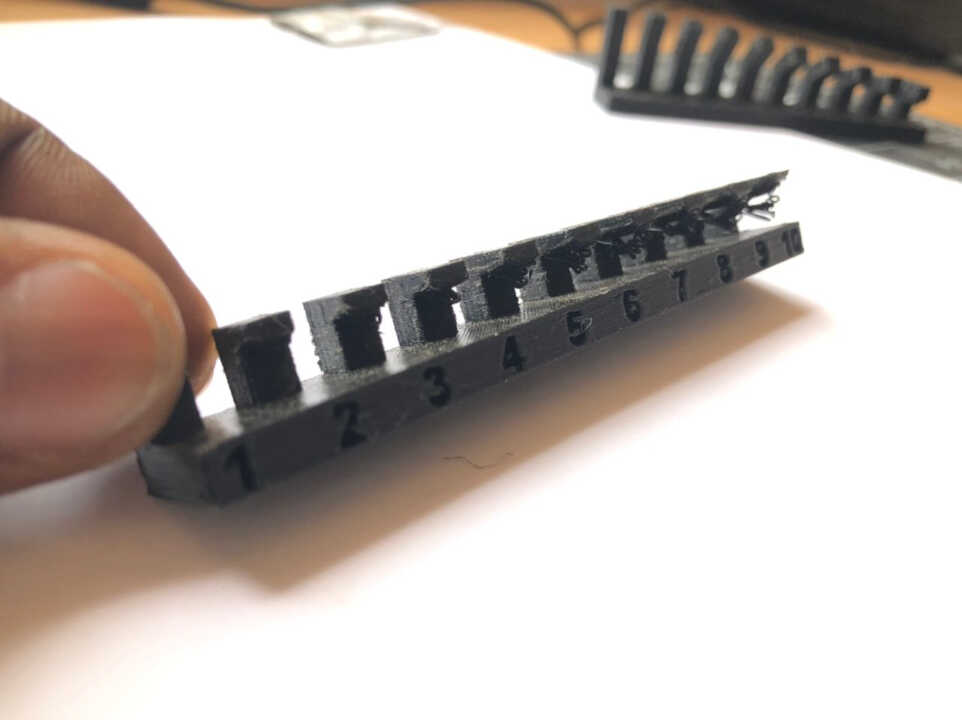
In this test, a piece was printed in which wall thicknesses were increased in an additive manner, and the gap between two walls was also printed. The results of this test showed that a minimum thickness of around 0.8mm is required before the wall will not be able to support itself and begin to deform.
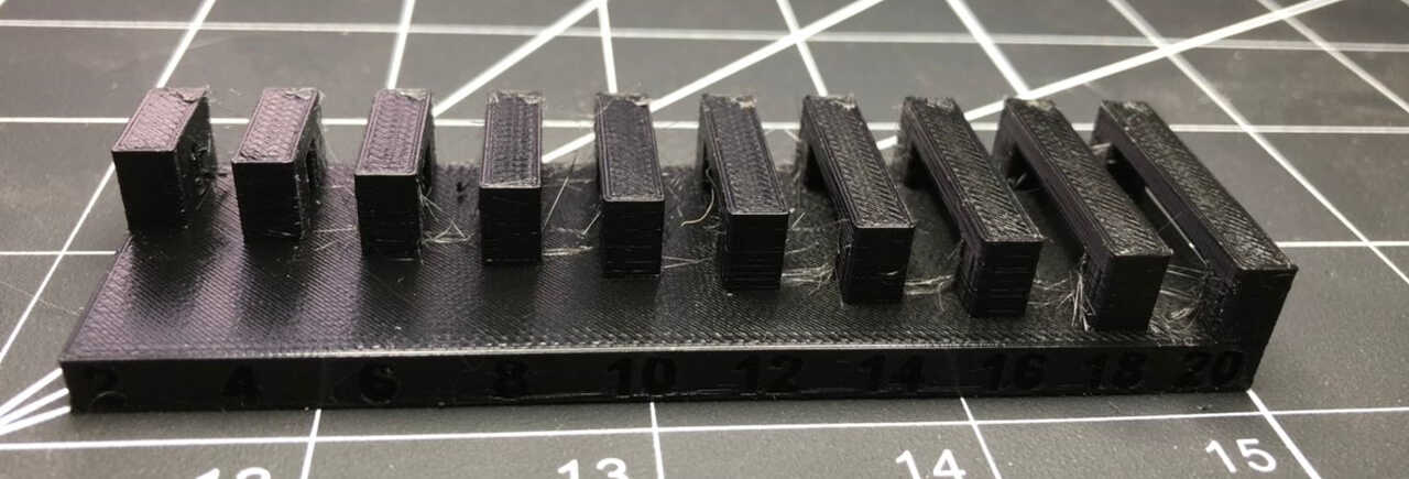
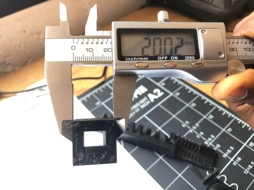
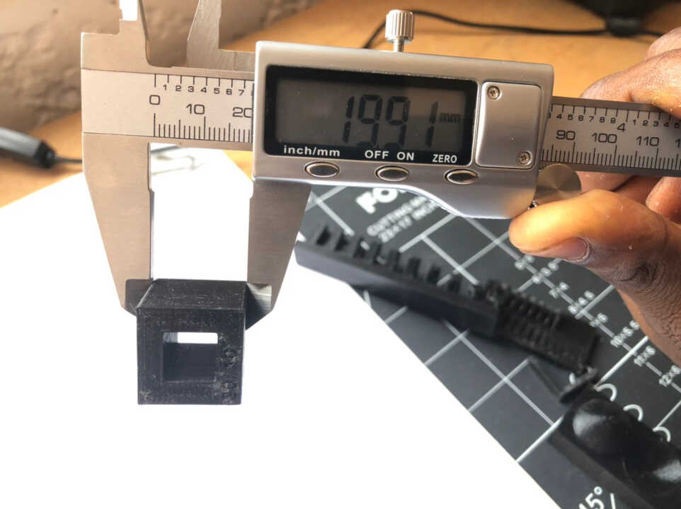
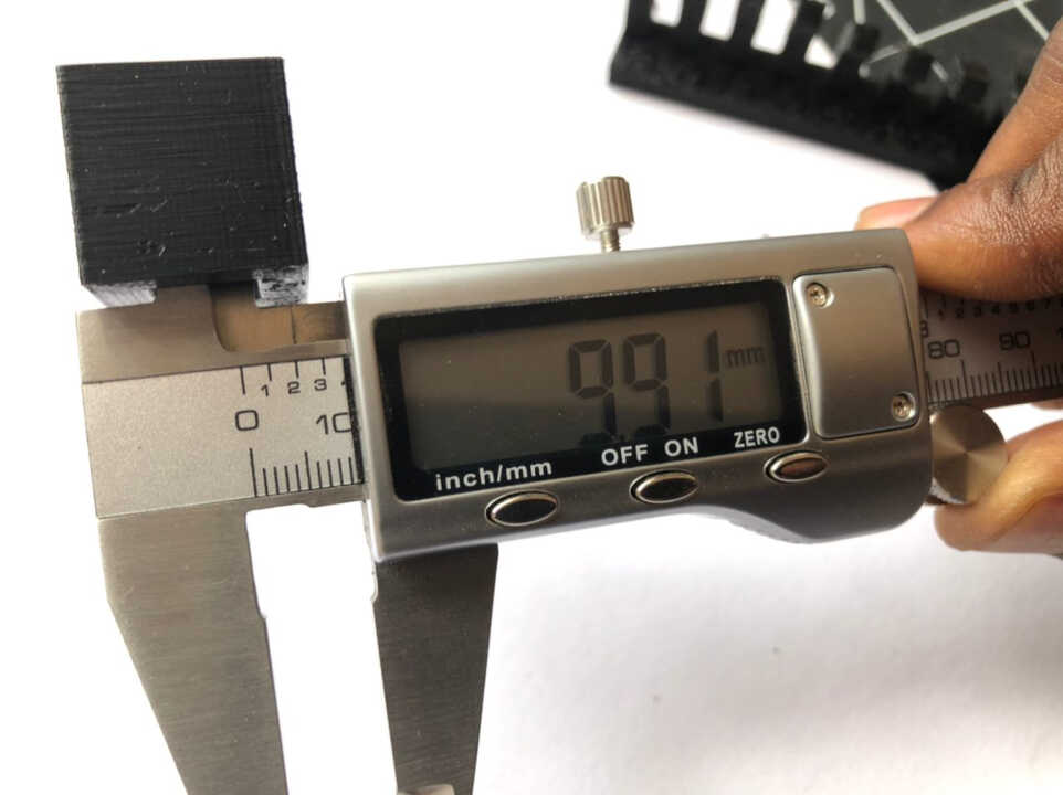
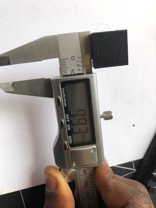
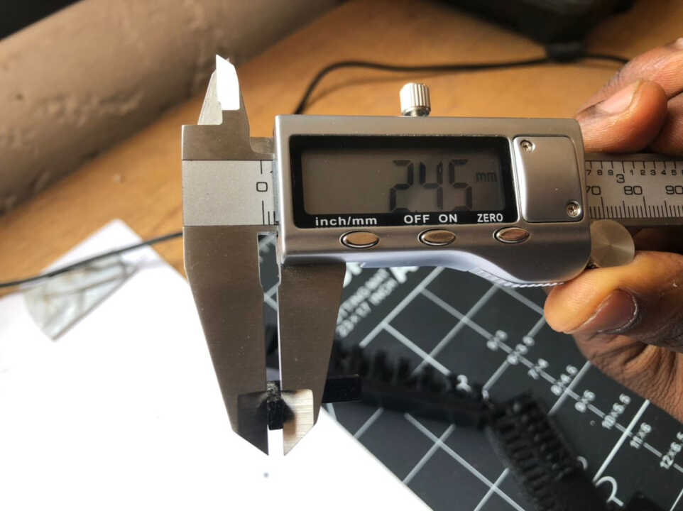
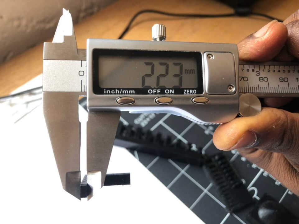
In this print, the accuracy of the dimensions is tested by comparing the printed dimensions as well against the original mesh file dimensions. This will be limited by the width of the extruded filament and the precision of the motors. The test piece had an outer width of 20 mm and an inner width of 10 mm. As demonstrated in the images below, the printer is fairly accurate with a nominally small margin of error.
In this test the difference between the accuracy of the printer when it is printing horizontally, vs. when it is printing vertically is characterized. This is done by printing a part that is equal in both the horizontal and vertical directions and comparing the actual print dimensions. The results are illustrated in the photos below:
In this test, we printed a piece that had gradually increasing overhangs to test what angle of departure can be used without supports. The results of the test were that we were able to print to an angle of about 30 degrees before having issues with the print results. The photos below indicate the results of these tests:
Individual assigment
3D Scanning
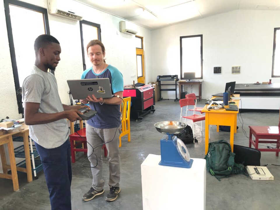
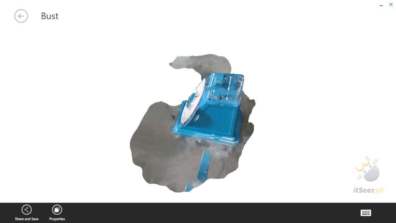
Methode 1: structured light
Structured light is a light whose characteristics are known (like a regular grid for example) is projected on the surface to be scanned in 3D. A sensor records the deformation of the light and deduces the shape of the 3D scanned surface.
The equipement
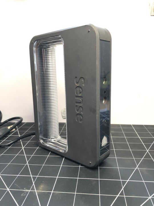
To apply the method of scanning by structured light we used the scanner 3d Sense.
Using the equipement
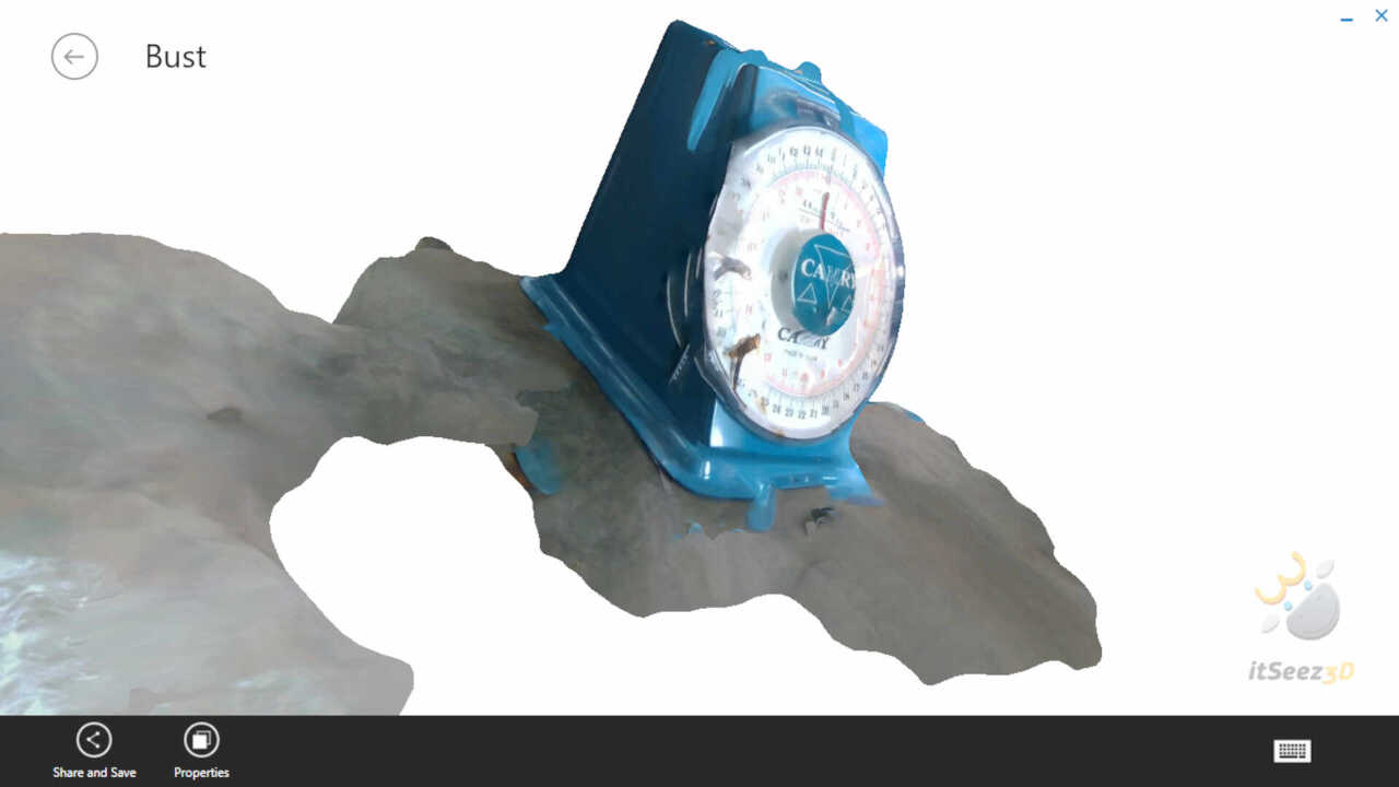
To perform the scan, we used a software called itSeez3D
you can watch this video to quickly understand the procedure.
- Outcome
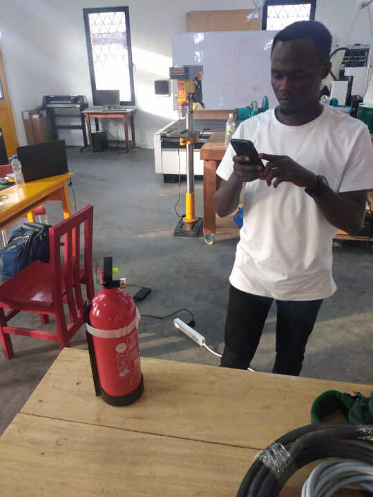
Methode 2: Photogrammetry
Photogrammetry is a technique that relies on the advanced computer analysis of the information contained in photographs. The extracted information allows to position in 3D the place where the photos were taken and to deduce the 3D scan of the subject (object, environment or person
The equipement
Any equipment that can take pictures could do the trick. In my case I just used my smart phone.
Using the equipement
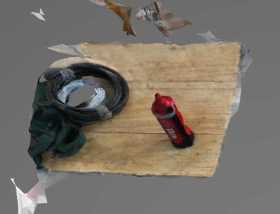
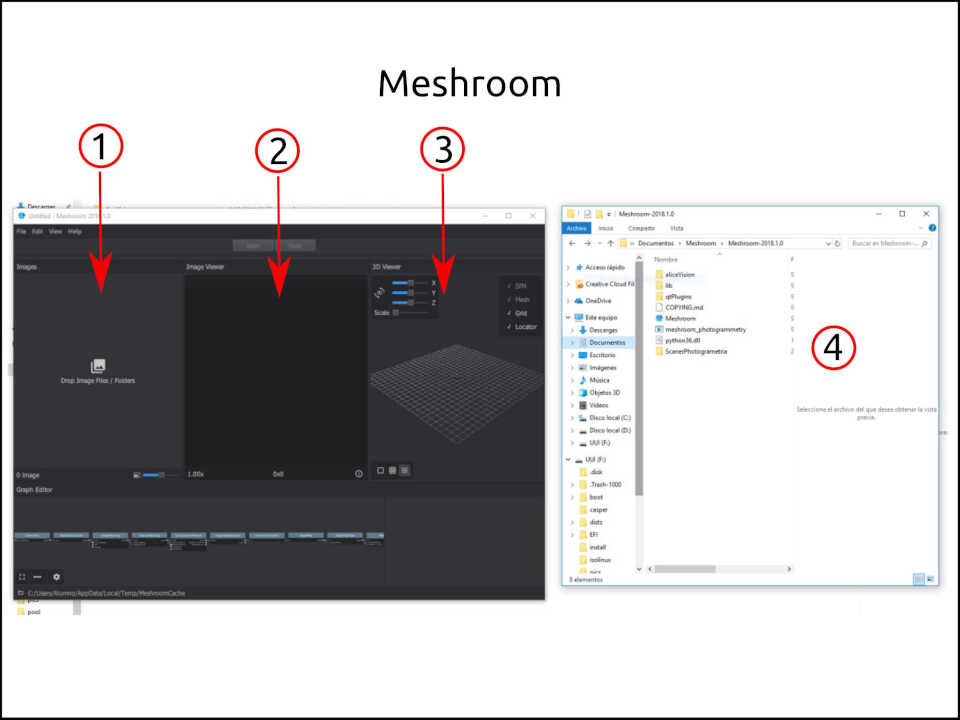
For the sofware I use Meshroom photogrametry software. Meshroom is a free, open-source 3D Reconstruction Software based on the AliceVision framework.
- Here you have to drag and drop your images.
- Here preview each image if you want to check them.
- Here the software shows you how the 3D object is generating
- Your images have to be in one place to select them at the same time.
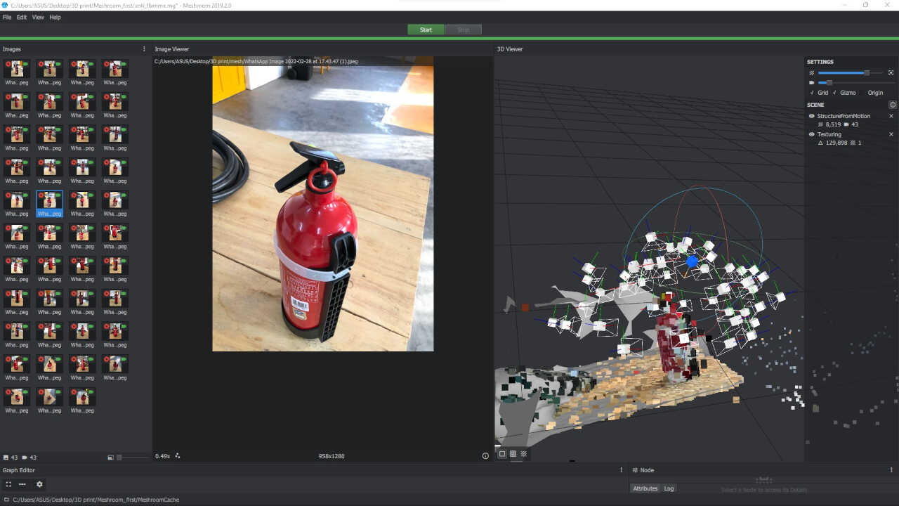
- Outcome
3D Printing a piece I designed
3D Design
For the personal assignment on 3D printing, I decided to design part of my final project.
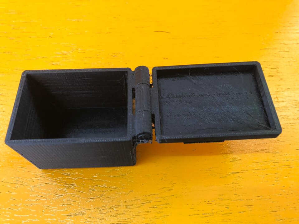
Unlike what I modeled in the week assignment of computer-aided design, this time I intend to model a removable box that can hold electronics in the future.
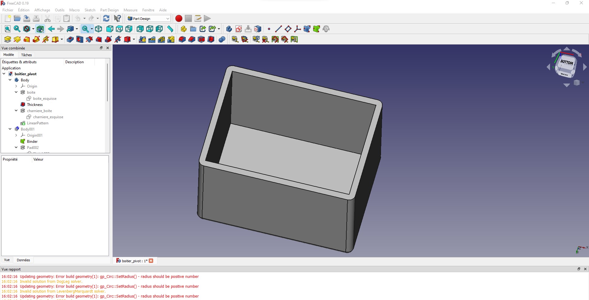
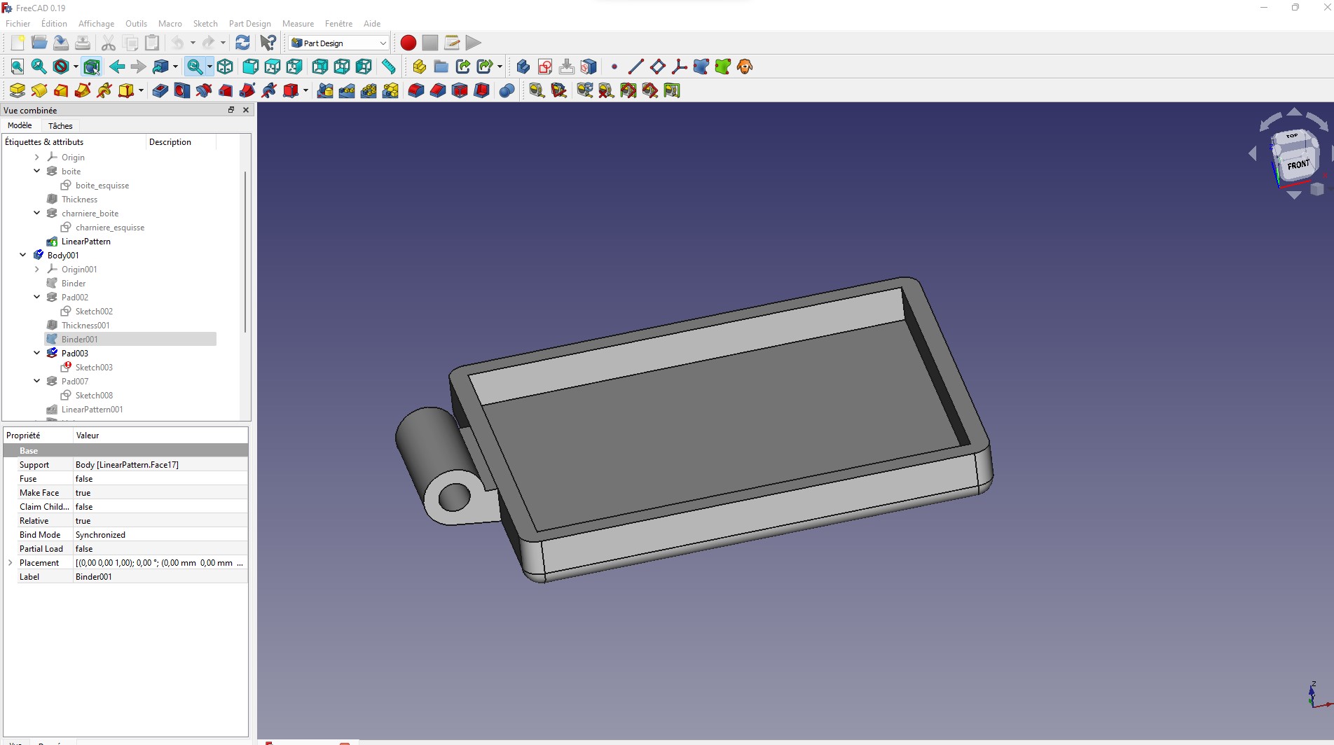
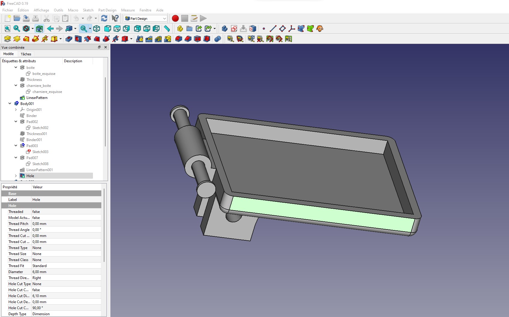
So I start the modeling on Freecad by creating a cube.
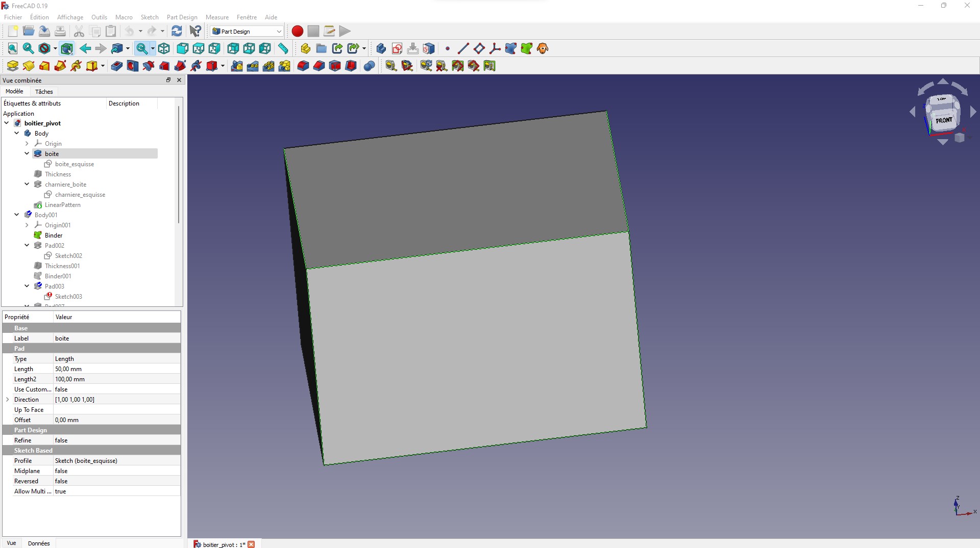
I create a hollow in the cube and then I create fillets to round the edges of the cube.
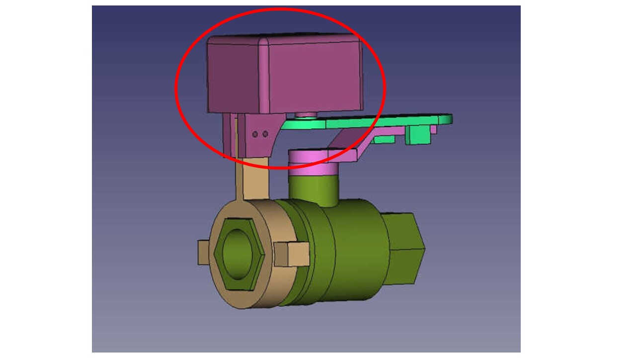
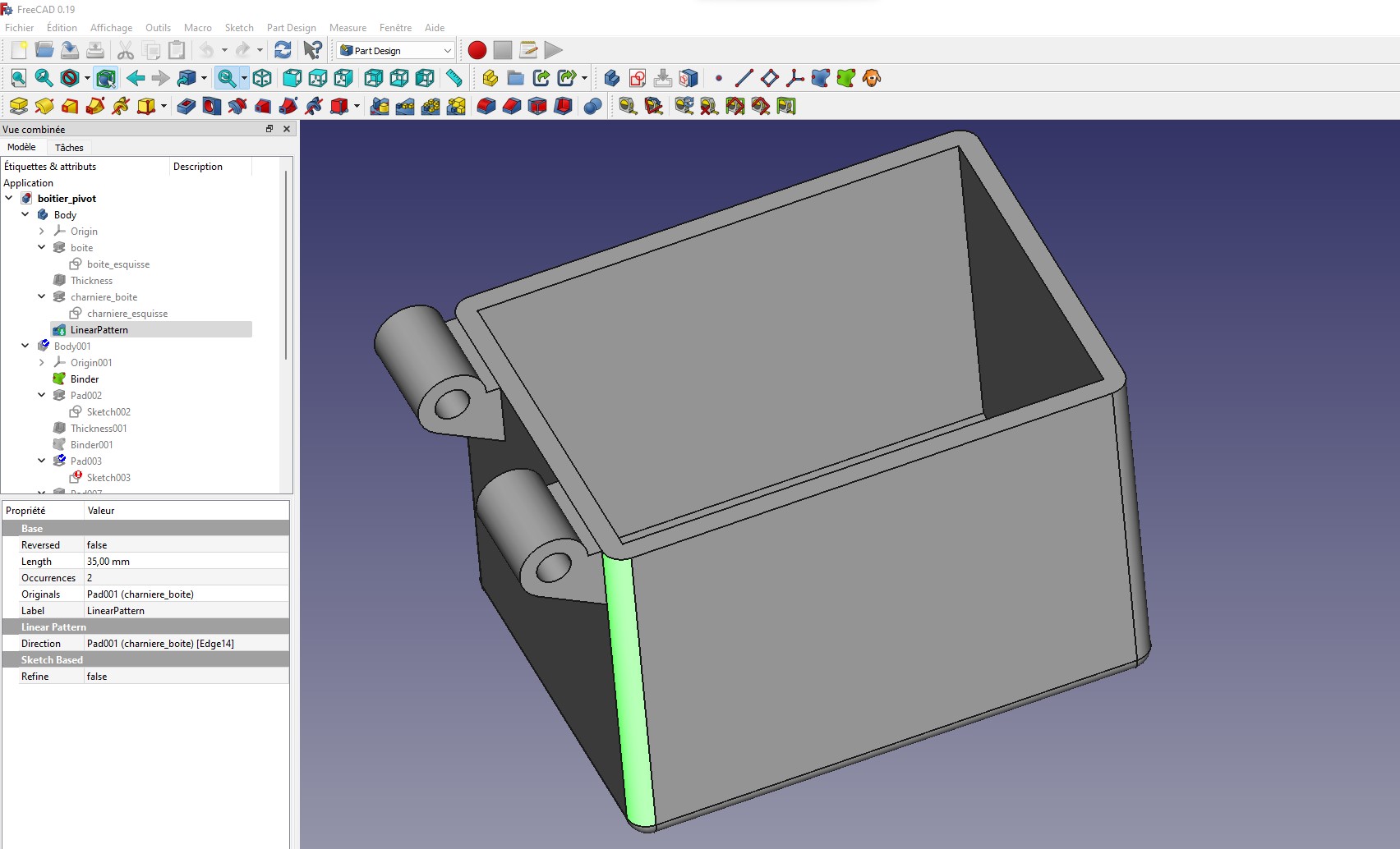
Here I create the hinge that will be associated with the lid hinge
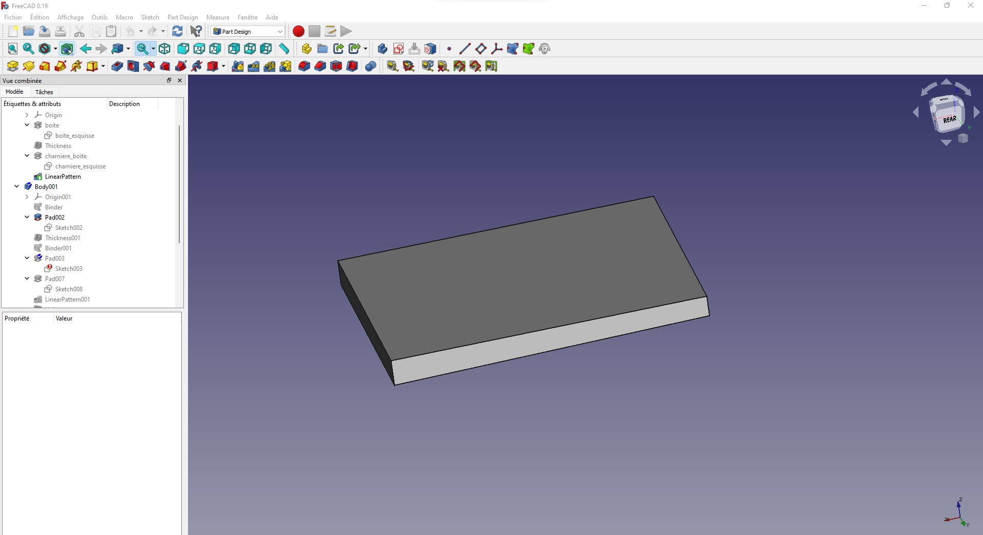
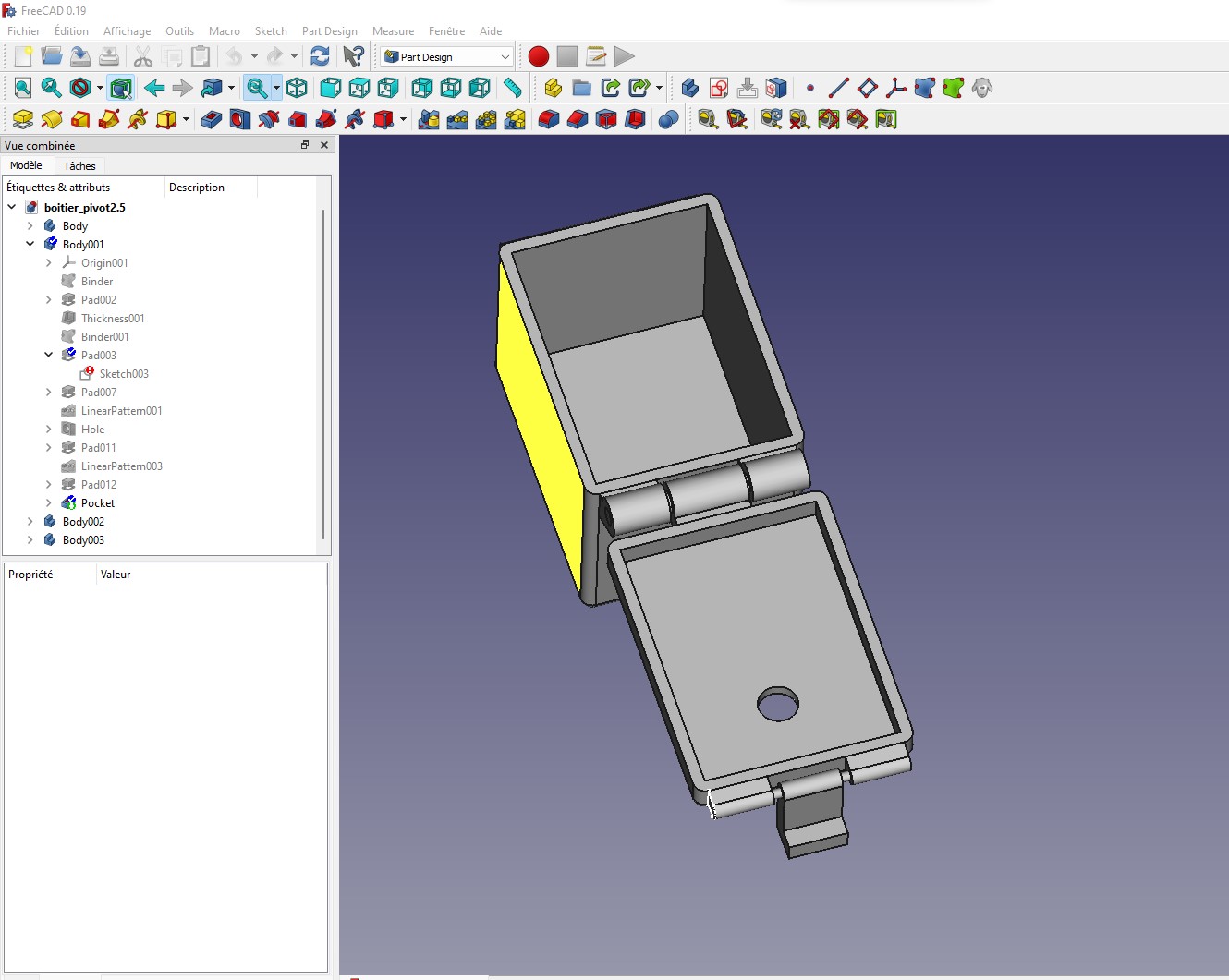
Then I go to the modeling of the lid of the box. I start with a rectangular paralelopiped
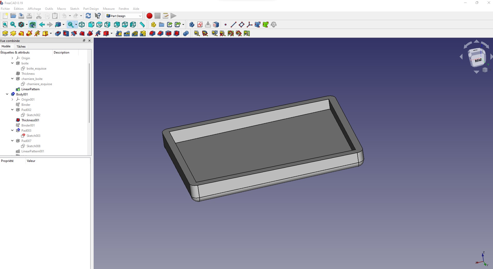
I create a small hollow inside the shape and create fillets on the edges.
Here I add the hinge that will fit the hinge of the box.
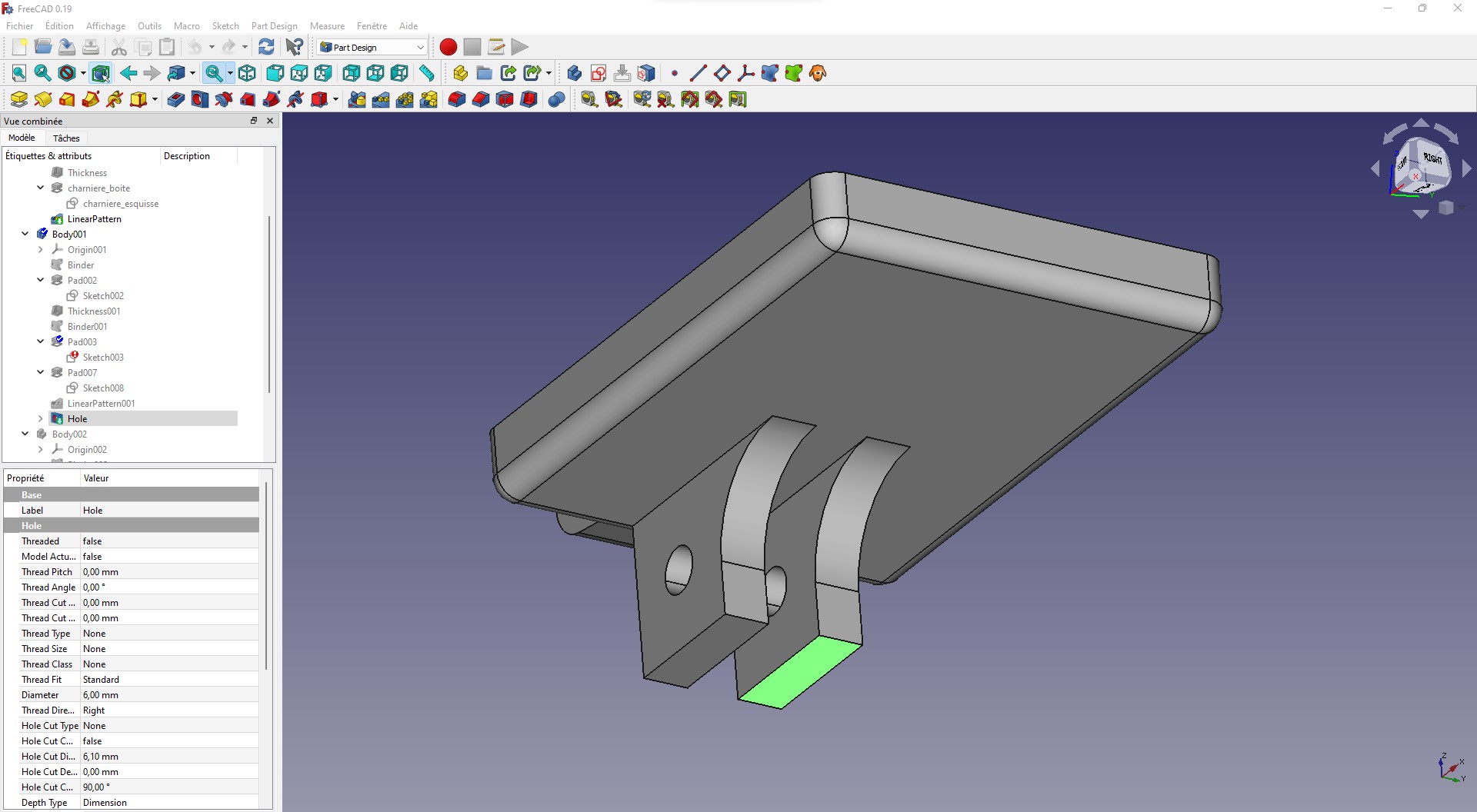
On top of the lid, I create some kind of feet that will serve to stabilize the whole box.
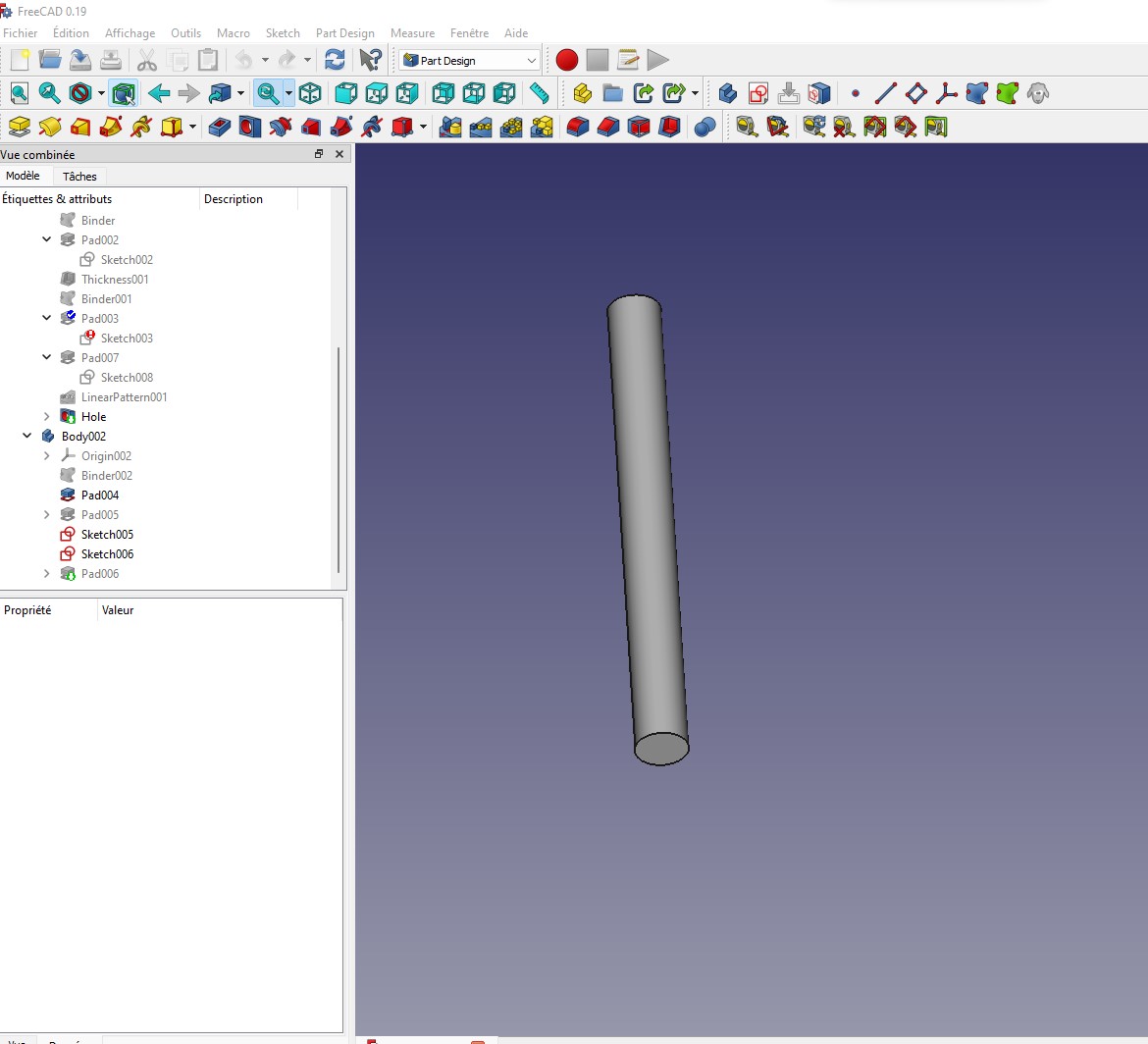
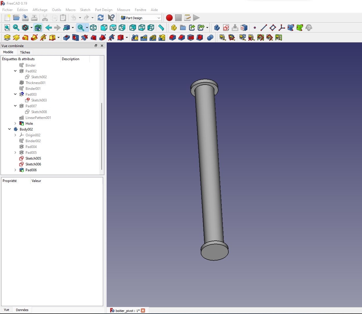
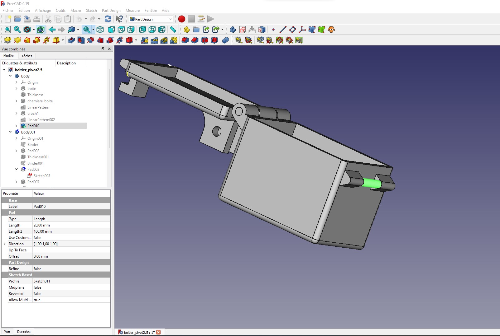
Here I create a short stick cylinder which will allow to associate the hinges
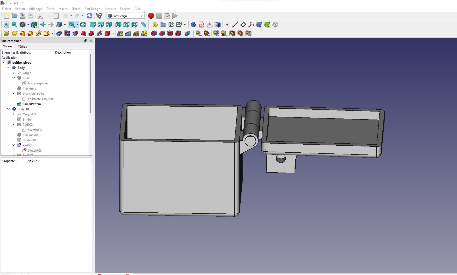
Here we see how it is placed on the cover
we combine the whole
I was going to stop there, but I had the idea to create a hook to close the box.
Here I model the place where the hook will be wedged to block the closing of the box
Slicing
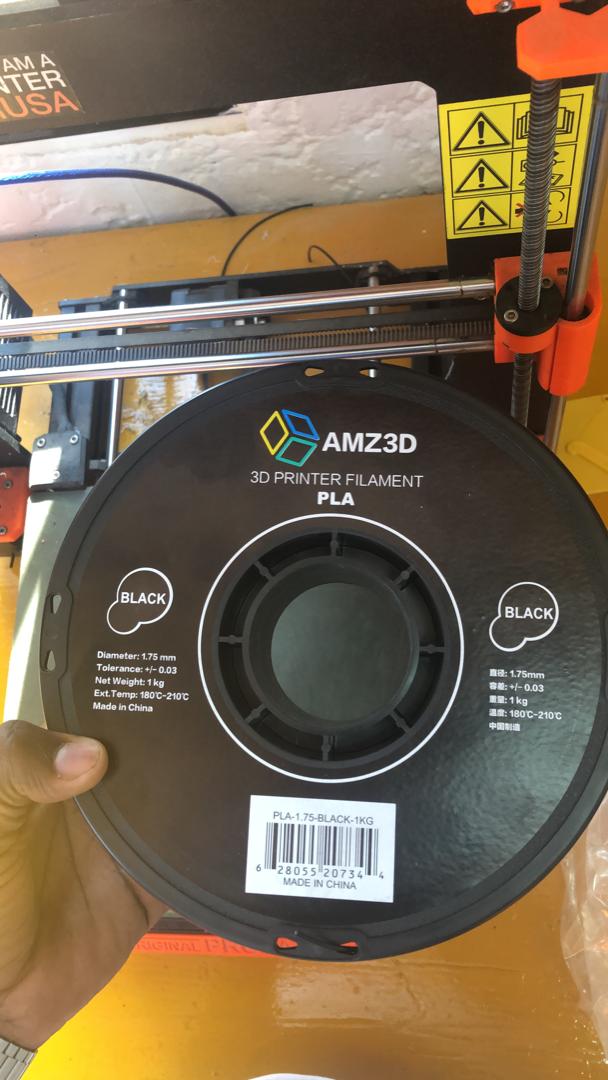
PLA(Polylactic acid) filament was used to print out this component.
The parameters used for slicing are below:
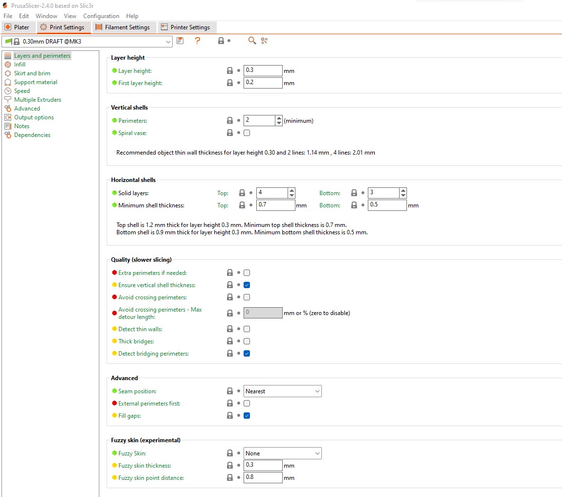
- Layer height: this image below shows the parameters for the layer height used for this print out
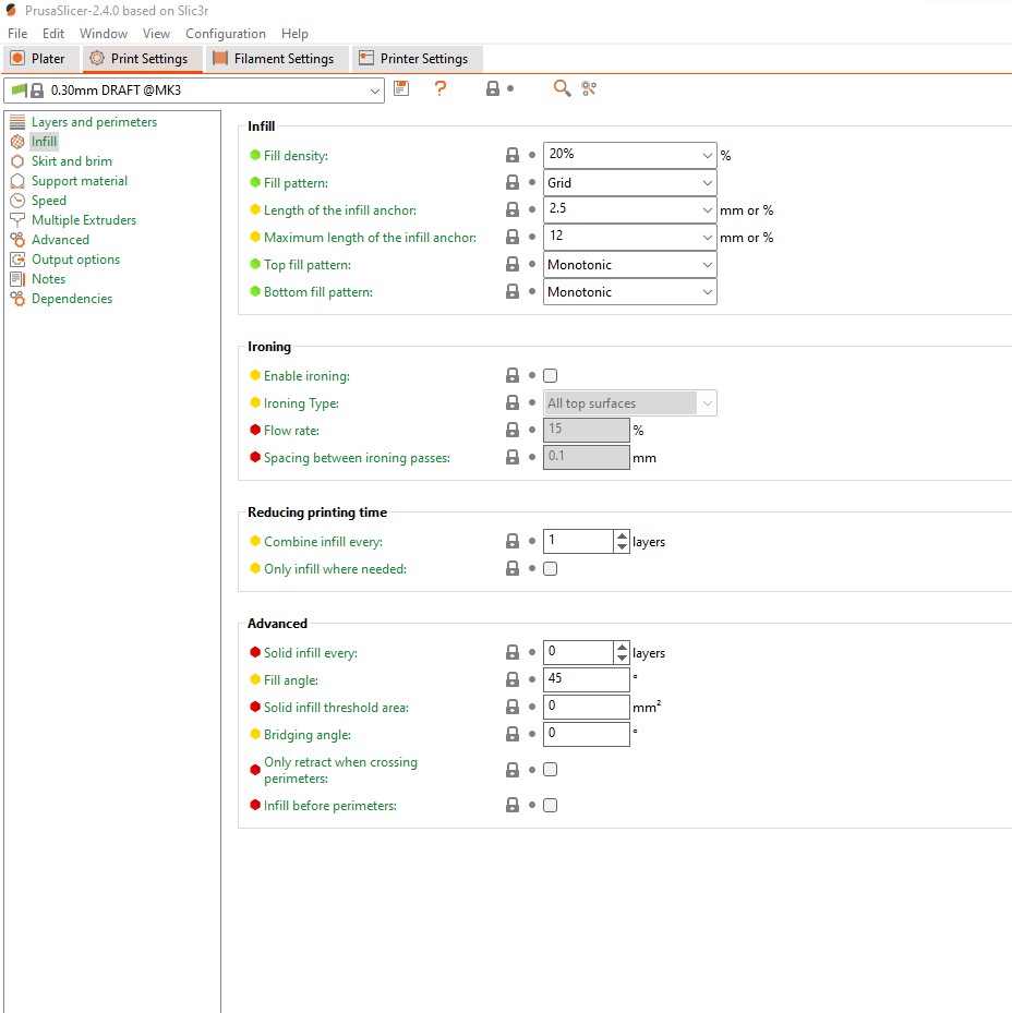
- Infill: this image below shows the parameters for the amount of infill and the partern used for this print out
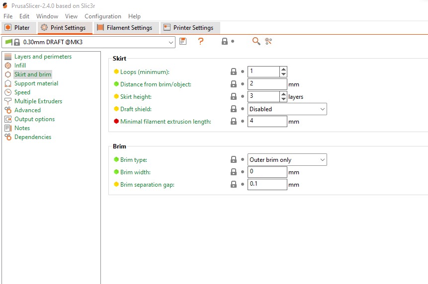
- Skirt and Brim: this image below shows the parameters for the skirt and brim used for this print out
- Support: this image below shows the parameters for the support material and the partern used for this print out
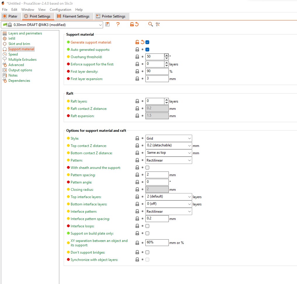
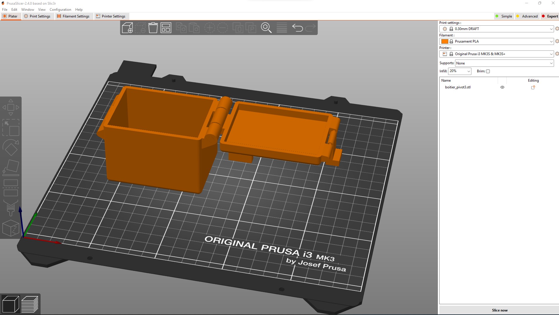
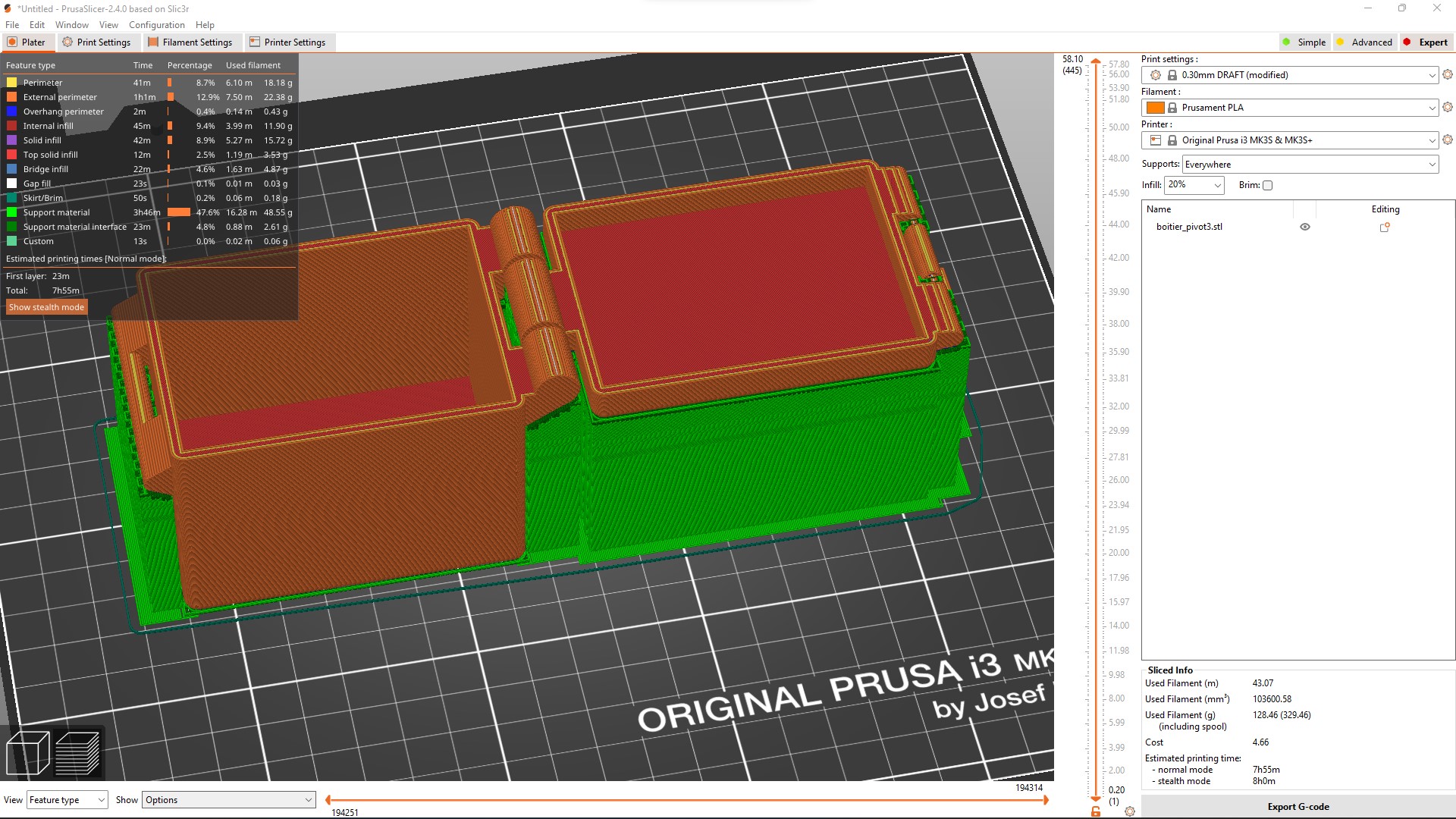
We can see in green in the image below how the supports will be on the object that will be printed.The slicer informs me in advance that the printing time will be 7h55mm.
The print-outs
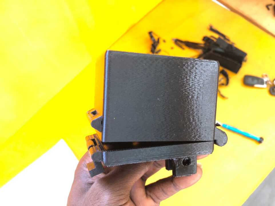
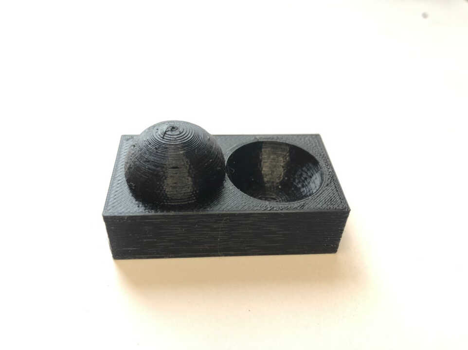
For printing, we used a black filament type PLA.
After finishing printing, here is the result below.
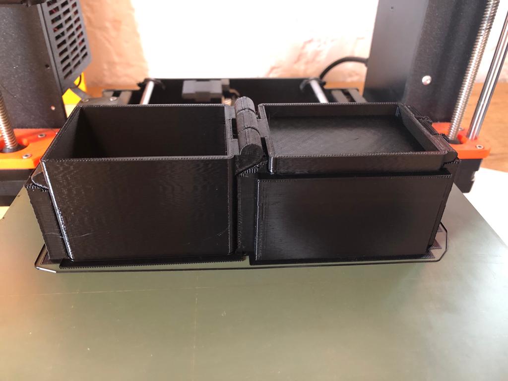
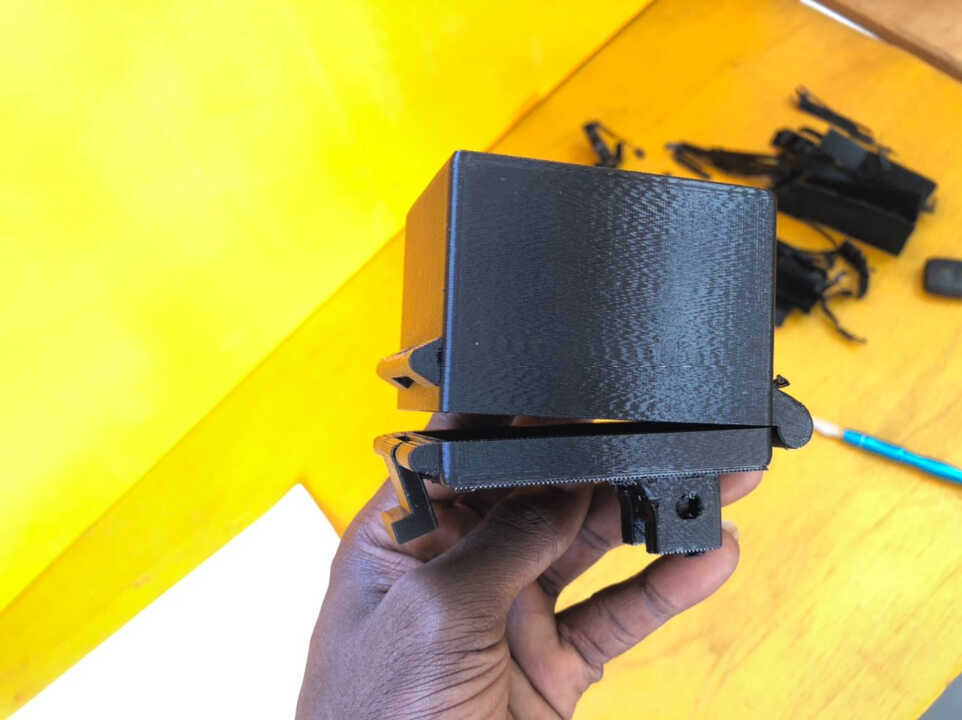
The distance between the bodies to be turned is 0.3 mm, and for the pivot radius 0.3 mm.
File
What went wrong/What went well
3D scan
What didn’t work was when we tried to use the 3D Sense 2 scanner with the software that goes with it. It didn’t work because the software didn’t recognize the activation key we have. That’s why we looked for another software and we found the itseez3d software that works well with the Sense 2 scanner.
3D print
For the 3D printing part, what didn’t work was when I first printed the object I modeled with a printer other than the Prusa.
The printer I used for the first test was an old DIY printer that we have in the fablab in addition to the prusa.
For the slicer I used the same as the one used on the Prusa with the same settings for printing.
After printing, the case cover could not move because the hinge was filled with filament.
The reason it didn’t work is that the printer had a lower print quality than the Prusa.
But in the end, this experience with the old 3D printer allowed me to better understand the importance of working together to determine the limits of the printer. Indeed, if I had done the printing tests for the old printer, it would have allowed me to take into account certain parameters when modeling the 3D object.