13. Input devices
Group assignment
In this week’s group task, we were asked to probe an input device’s analog levels and digital signals and below are the results of the task.

In the video above, it shows the readings when the input device was probed using the osciloscope in the lab. This was reading the analog value of the Soil moisture sensor, the line depicting the variation in signal as the level is changed. The value is between 0 -5v
The video above shows the readings when digital signals where being applied. The values are either 0v or 5v it does not vary as the moisture level varies.
individual assignment
For the individual assignment we were tasked with adding a sensor to a microcontroller board that we have designed and reading it. To do this I intend to use the ESP32 microcontroller by adding a soil moisture sensor and a voltage sensor. These elements will be part of my final project.
Workflow
- read the data sheet of the different components to be used
- design and produce the electronic board and Connect your sensors to your microcontroller board
- Program your microcontroller to read your sensor
1. The data sheet of the different components
ESP32
The ESP32 chip comes with 48 pins with multiple functions. Not all pins are exposed in all ESP32 development boards, and some pins cannot be used.
The figure below illustrates the ESP-WROOM-32 pinout.

| Specifications | |
|---|---|
| Integrated crystal | 40 MHz crystal |
| Integrated SPI flash | 4 MB |
| Operating voltage/Power supply | 3.0 V ~ 3.6 V |
| Operating current | Average: 80 mA |
| Minimum current delivered by power supply | 500 mA |
| Architecture | 32 bits |
| Wi-Fi | 2.4 GHz up to 150 Mbits/s |
| Bluetooth | BLE (Bluetooth Low Energy) and legacy Bluetooth |
| Peripherals | Capacitive touch, ADC (analog to digital converter), DAC (digital to analog converter), I2C (Inter-Integrated Circuit), UART (universal asynchronous receiver/transmitter), CAN 2.0 (Controller Area Netwokr), SPI (Serial Peripheral Interface), I2S (Integrated Inter-IC Sound), RMII (Reduced Media-Independent Interface), PWM (pulse width modulation), and more. |
soil moisture sensor
The soil moisture sensor consists of two probes which are used to measure the volumetric content of water. The two probes allow the current to pass through the soil and then it gets the resistance value to measure the moisture value.m

When there is more water, the soil will conduct more electricity which means that there will be less resistance. Therefore, the moisture level will be higher. Dry soil conducts electricity poorly, so when there will be less water, then the soil will conduct less electricity which means that there will be more resistance. Therefore, the moisture level will be lower.
Input Voltage: 3.3 – 5V Output Voltage: 0 – 4.2V Input Current: 35mA Output Signal: Both Analog and Digital Pin Out The soil moisture sensor has four pins:
VCC: Power A0: Analog Output D0: Digital Output GND: Ground The Module also contains a potentiometer which will set the threshold value. This threshold value will be compared by the LM393 comparator. The output LED will light up and down according to this threshold value.
To connect the sensor in the analog mode, we will need to use the analog output of the sensor. When taking the analog output from the soil moisture sensor, the sensor gives us a value from 0 to 1023. The moisture is measured in percentage, so we will map these values from 0 to 100 and then we will show these values on the serial monitor.
Connections
The connections for the soil moisture sensor to the ESP32 are as follows:
VCC of the sensor to 3v3 of the Wemos GND of the sensor to GND of the Wemos A0 of the sensor to GPIO 35 of the ESP32
2. Electronic design and production
a. Schematic
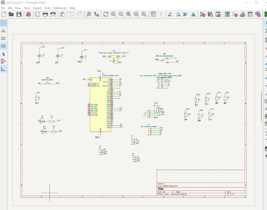
The first step in the design is the creation of the schematic. The board will need an I2C pin for I2C communication, a FTDI pin for programming and debugging and a pin for the soil moisture sensor.
Here is the electronic schematics of the board to be made
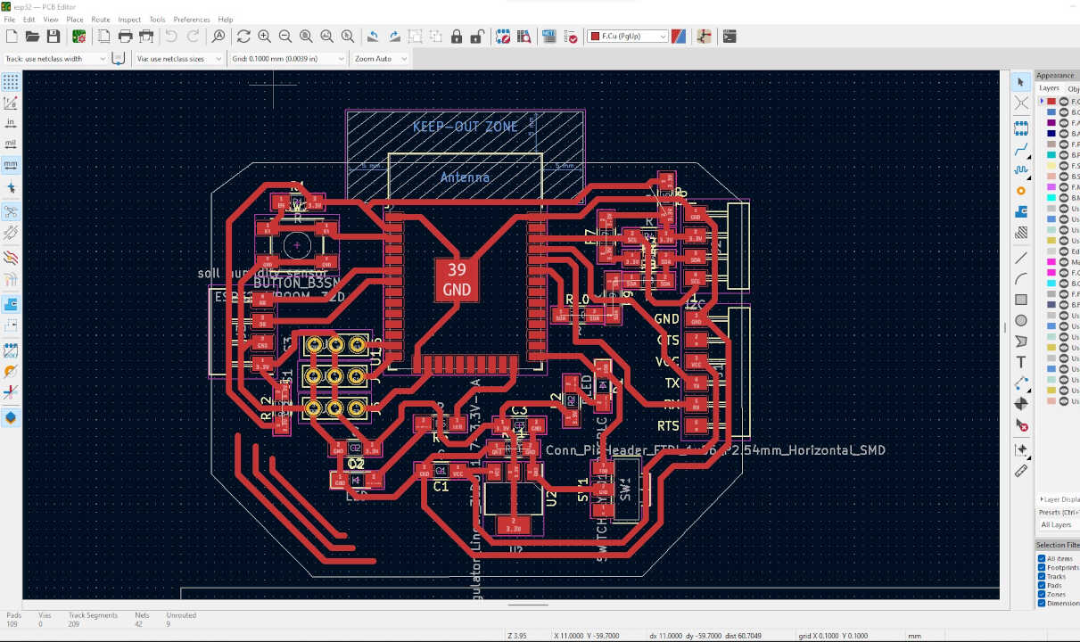
b. pcb layout
After having made the schematic we model the traces of the circuit as well as the shape of the board in the pcb editor as shown below.
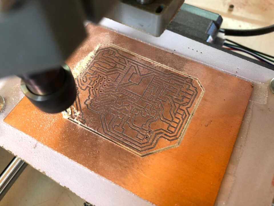
c. Milling pcb
We have finished with the PCB design, we can now mill it with the milling machine.
d. Soldering
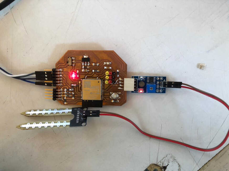
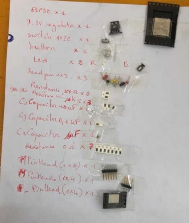
We collect all the components to be used before soldering the components on the pcb.
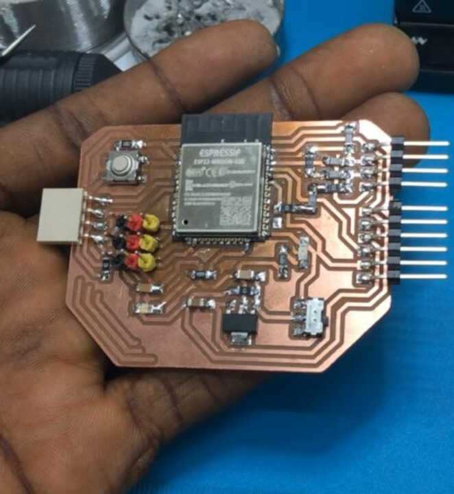
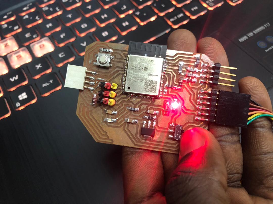
In the picture below we can see the final representation of the pcb after soldering
3. Programming
Before we start programming, we must first install the EPS32 board in the Arduino IDE.
To install the ESP32 board in our Arduino IDE, follow these next instructions:
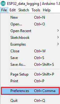
- In thne Arduino IDE, we go to File> Preferences
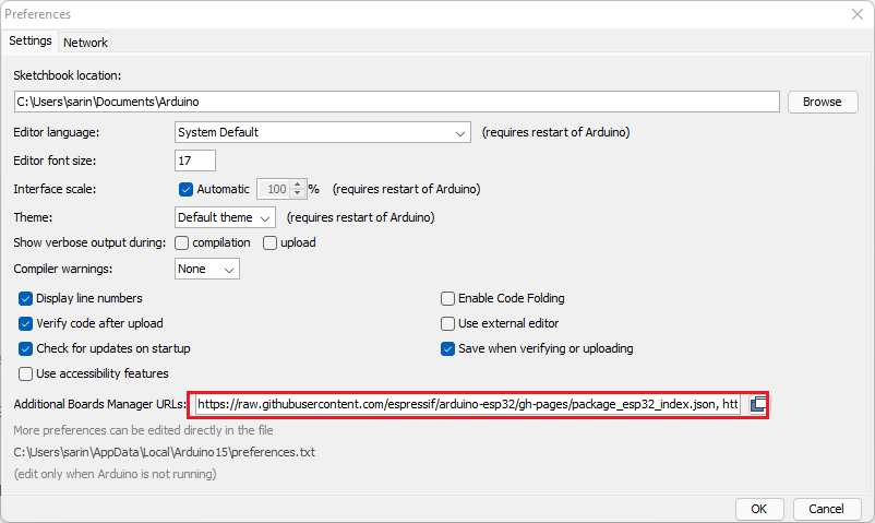
- Enter the following into the “Additional Board Manager URLs” field:
https://raw.githubusercontent.com/espressif/arduino-esp32/gh-pages/package_esp32_index.json
Then, we click the “OK” button:
Note: we already have the ATtiny boards URL so we separate the URLs with a comma as follows:
http://drazzy.com/package_drazzy.com_index.json,https://raw.githubusercontent.com/espressif/arduino-esp32/gh-pages/package_esp32_index.json
- We open the Boards Manager. We go to Tools > Board > Boards Manager…
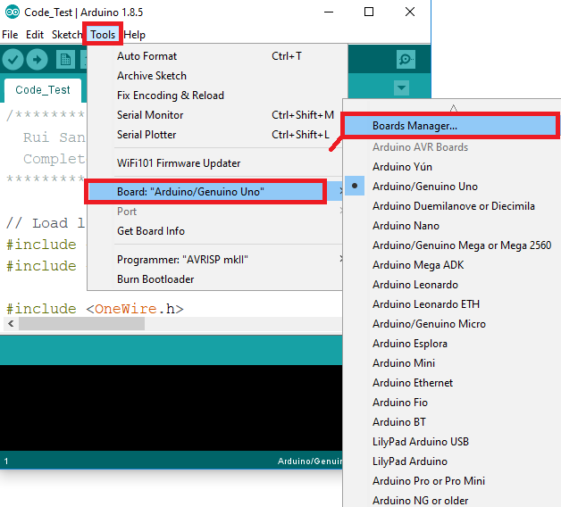
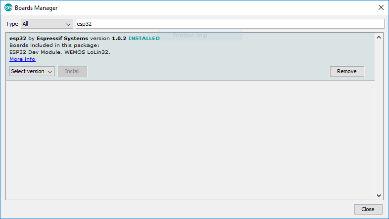
- We search for ESP32 and we press install button for the “ESP32 by Espressif Systems“:
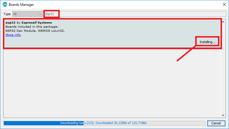
- That’s it. It should be installed after a few seconds.
Now that the board is installed we connect the board to the computer using the FTDI cable
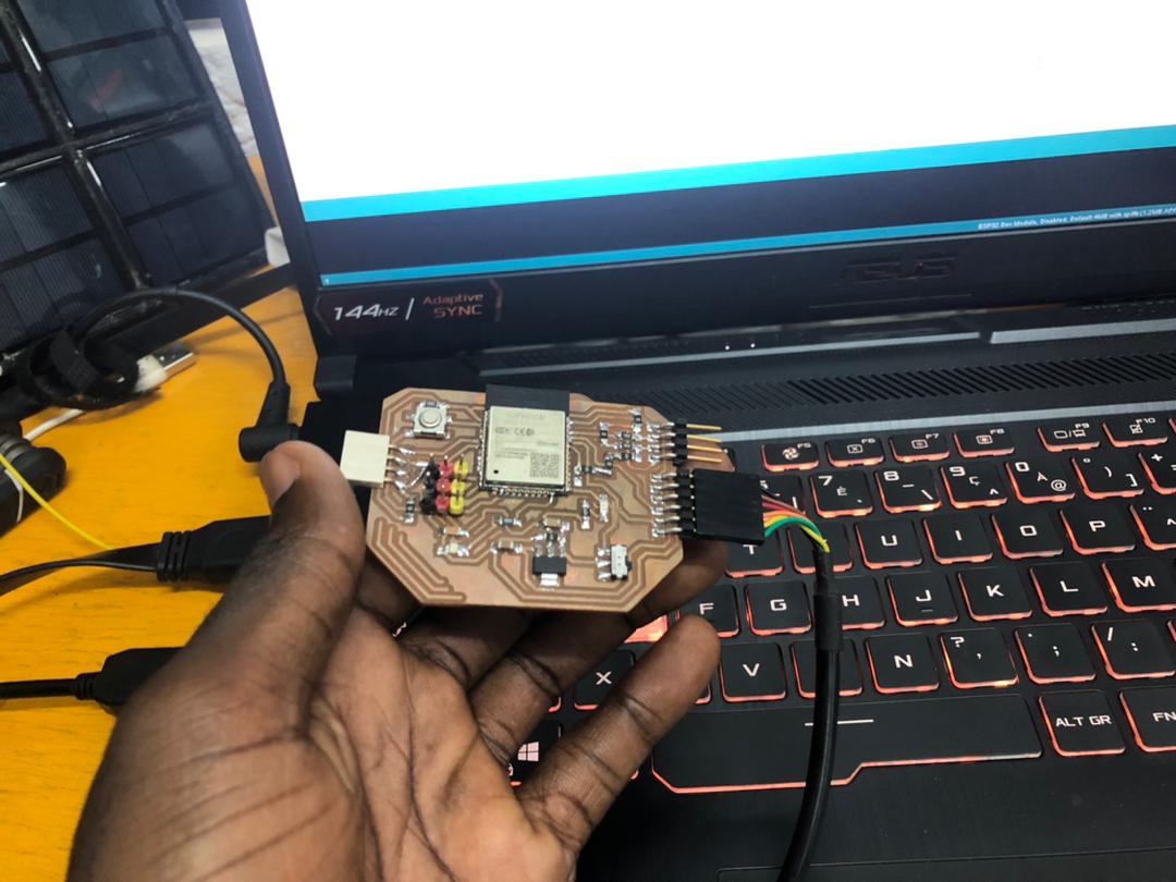
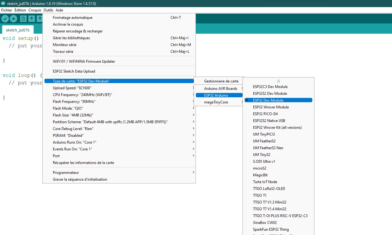
We select our Board in Tools > Board menu (ESP32 Dev Module)
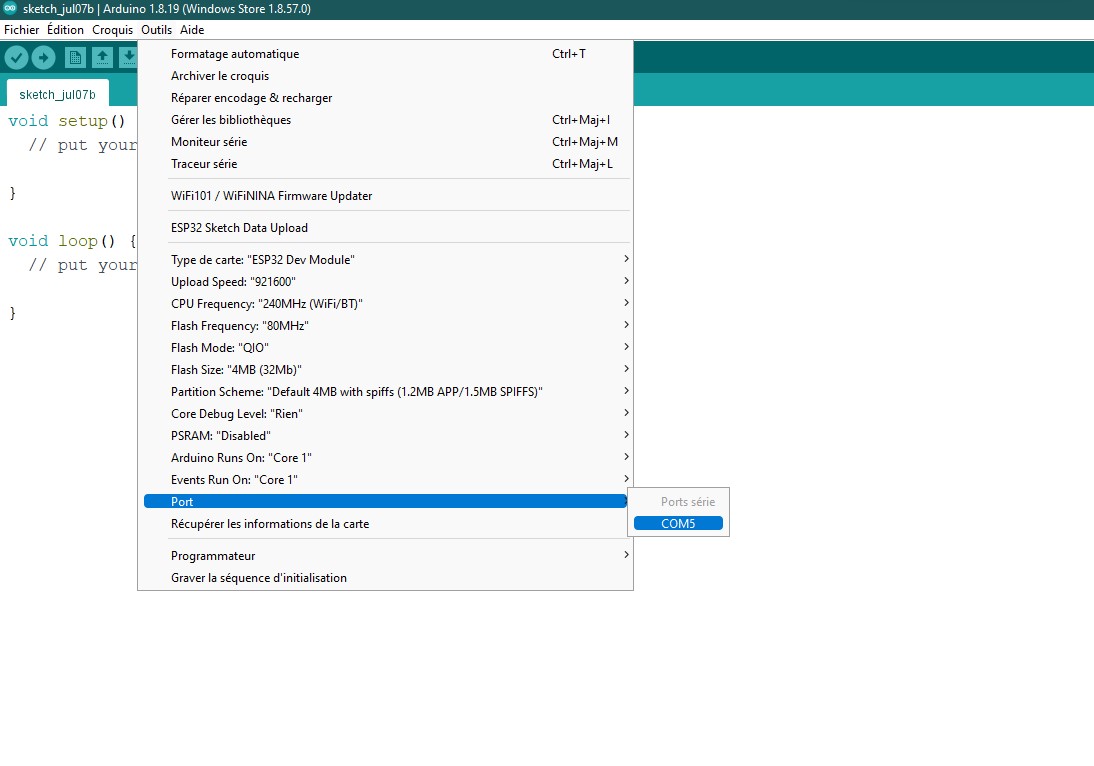
We select the port used by the FTDI cable
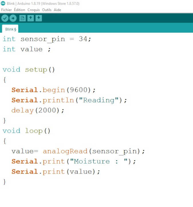
We can move on to the actual programming
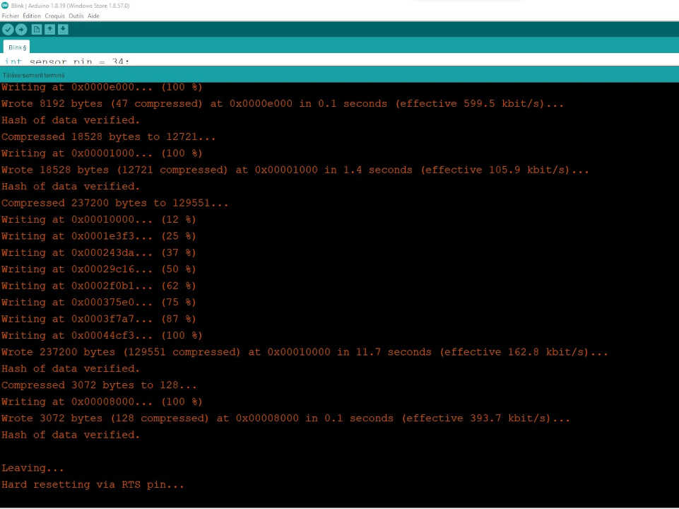
After we finish writing the program, we download it.
At the beginning of the download process, we need to put the board in flash mode by activating the slide switch and clicking once on the push button.The red light on the board indicates that the flash mode is active.
We can see below that the upload went well.
We disable the fash mode and we reset the board by clicking on the push button
In the video below, you can see the information from the humidity sensor that is displayed on the arduino serial monitor.
The analog value of the sensor ranges from 4095 (in air) to 1860 (in water).
I decided to write a second program that will turn on the led on the board when the humidity is below the analog value 3000. The led is connected to the gpio 2 of the esp32 chip
int sensor_pin = 34;
int led= 2;
int value ;

void setup()
{
  Serial.begin(115200);
  pinMode(led,OUTPUT);
  Serial.println("Reading");
  digitalWrite(led,1);
  delay(1000);
  digitalWrite(led,0);
  delay(1000);
}
void loop()
{
  value= analogRead(sensor_pin);
  Serial.print("Moisture : ");
  Serial.println(value);
  if (value < 3000)
  {
    digitalWrite(led,1);
  }
  else
  {
    digitalWrite(led,0);
  }
}
You can see how the code works in the video below
Files
What went wrong/What went wel
For this mission, everything went well overall. At first, I struggled to upload my program to the board without success. It was after reviewing my electronic schematic that I realized that my error was the Rx pin of the FTDI pin being connected to the Rx of the ESP32 chip instead of the Tx and that the Tx pin of the FTDI pin should be connected to the Rx of the ESP32 chip.
I solved it by using connectors to attach the FTDI cable to my board by connecting the Rx(ftdi) to the Tx(of the board) and the Tx(ftdi) to the Rx(of the board).