11. Output device
Assignment Overview
Group assignment:
- Measure the power consumption of an output device
- Document your work to the group work page and reflect on your individual page what you learned
Individual assignment:
- Add an output device to a microcontroller board you’ve designed and program it to do something
Group assigment
This week’s group assignment was to measure the power consumption of an output device. So we measured the power consumption of a 12 volt DC fan. To do this, we used an oscilloscope from aiisun (model EM125) and two multimeters from Kaiweets (model HT118A).
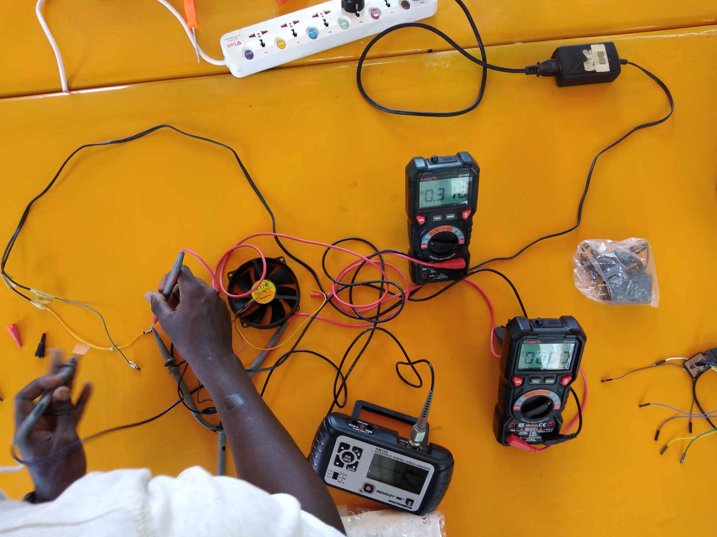
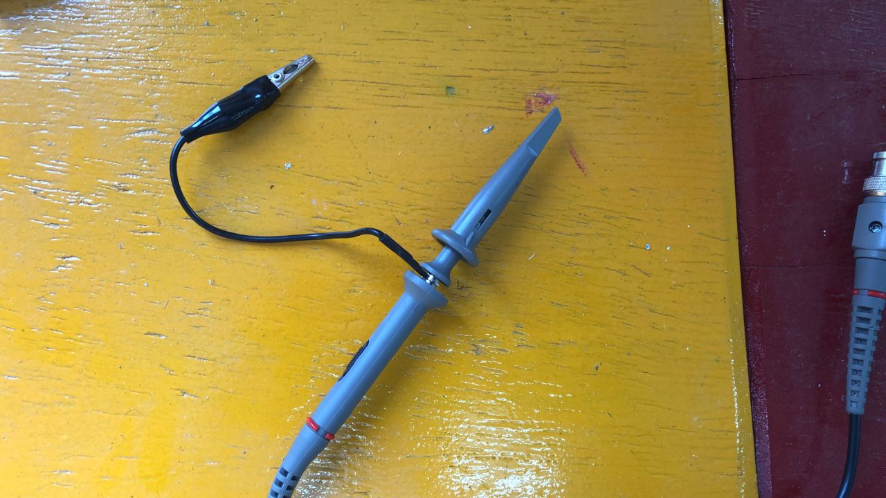
The purpose of the oscilloscope was to observe the evolution of the voltage used by the fan. To do this, we connect the probe of the oscilloscope to the positive terminal of the fan and the ground of the probe to the negative terminal of the fan.
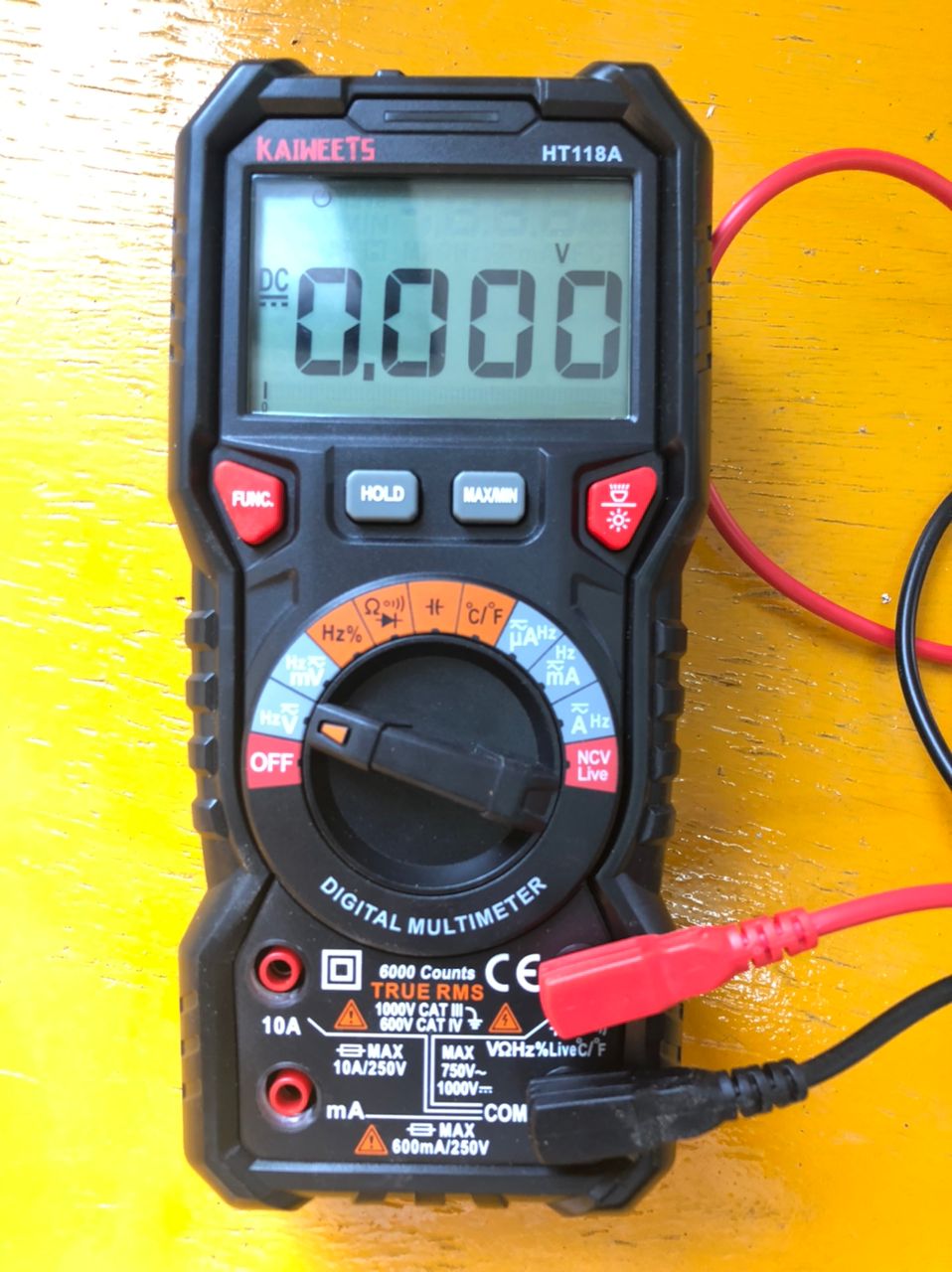
Then one of the two multimeters is connected in parallel to the fan to observe the voltage. This multimeter will be connected in the same way as the oscilloscope, that is, the positive terminal of the multimeter will be connected to the positive terminal of the fan and the other terminal will be connected to the negative terminal of the fan. The image below shows the configuration made on the multimeter to measure the voltage.
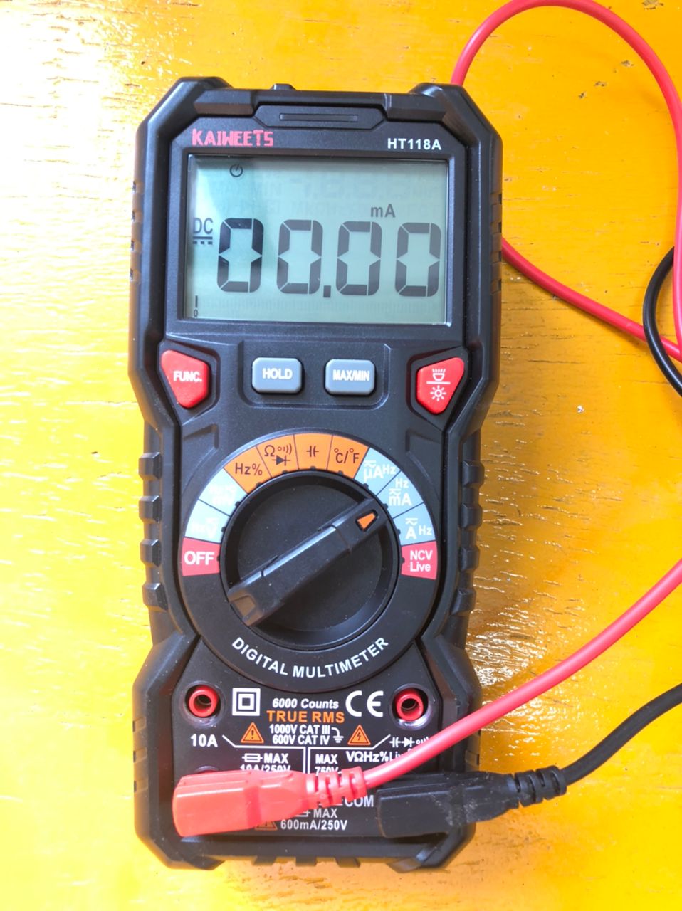
The second multimeter for measuring current will be connected in series with the fan, i.e. the positive terminal of the multimeter is connected to the negative terminal of the fan. The positive terminal of the fan is connected to the positive terminal of the power source, which is a 12V transformer in our case, and the negative terminal of the multimeter is connected to the negative terminal of the power source. The image below shows the configuration of the multimeter for current measurement.
The image below shows the measurements taken.
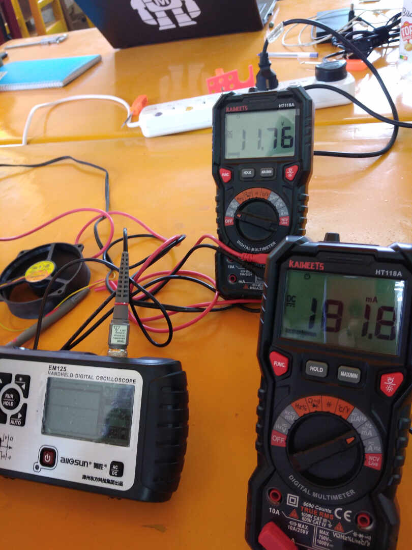
we observe that for the measurement of the voltage we get 11.76V and for the current we get 181.8mA.
So the power consumed is = voltage * current power = 11.76V * 181.8mA power = 2 137.97(VmA)
Individual assignment
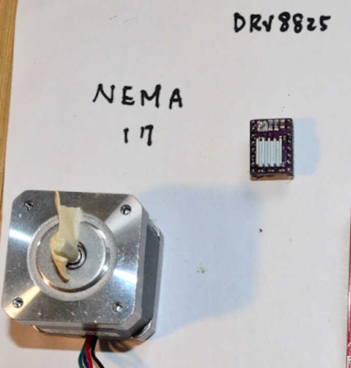
For this individual assignment, I need to add an output device to a microcontroller and program it for a specific function. According to my final project, my system is based on a microcontroller that drives a stepper motor to open and close a manual valve. So for my work, I will design an electronic board to drive a stepper motor. The motor I will use for this work will be a Nema 17 driven by the DRV8825 driver.
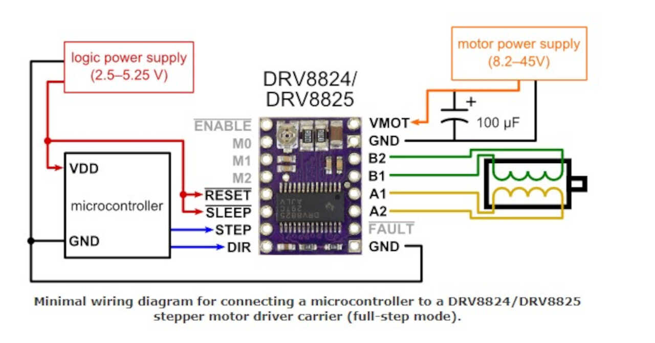
Driver wiring
Before starting it is important to see how the stepper motor driver works
Arduino test
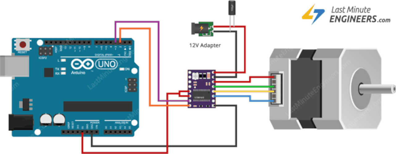
Now that we understand the connection to make the driver work, we will do a quick test with an Arduino board to make sure that everything works well. For this part with the aurduino I followed the page of lastminuteengineers
-
wiring
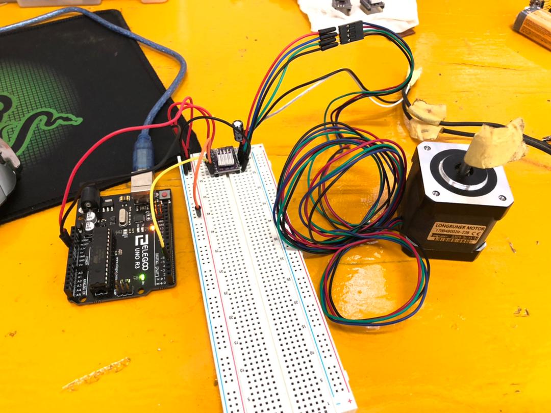
The connection finished, we can now move on to the arduino code
- Program
#define dirPin 4
#define stepPin 3
#define stepsPerRevolution 200

void setup() {
delay(5000);
pinMode(stepPin, OUTPUT);
pinMode(dirPin, OUTPUT);
}

void loop() {

digitalWrite(dirPin, HIGH);

// Spin the stepper motor 1 revolution slowly:
for (int i = 0; i < stepsPerRevolution; i++) {
    // These four lines result in 1 step:
    digitalWrite(stepPin, HIGH);
    delayMicroseconds(2000);
    digitalWrite(stepPin, LOW);
    delayMicroseconds(2000);
}
delay(1000);
}
Electronic Design
- ATtiny 412 pinout
For my system, I plan to use the ATtiny 412 microcontroller, so it is important to read the information about the inputs and outputs of this board before making the electronic schematic on KiCad.
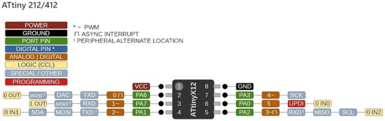
After having read the information on the inputs and outputs of the microcontroller, I can now build the electronic circuit of my board.
- Kicad Schematic
For this board I will need to have inputs/outputs for I2C communication, an input for UPDI programming, a 12V input for powering the board and the motor driver and finally an output for connection to the stepper motor.
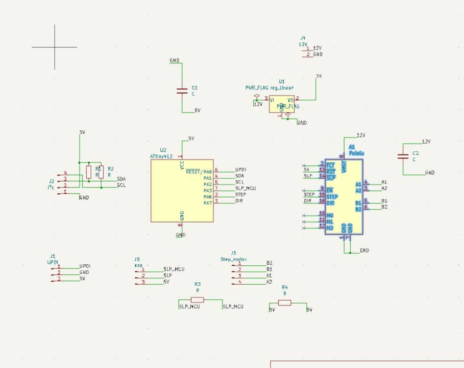
After completing the electronic schematic, we can now design the board.
-Kicad layout design
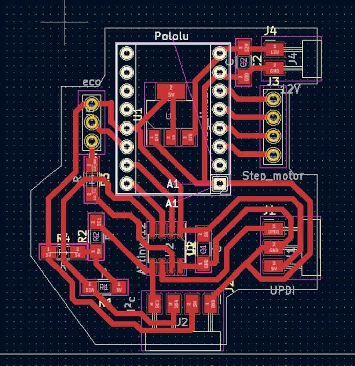
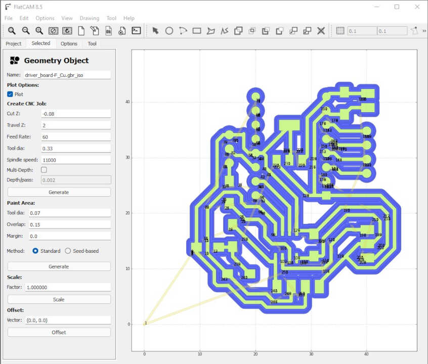
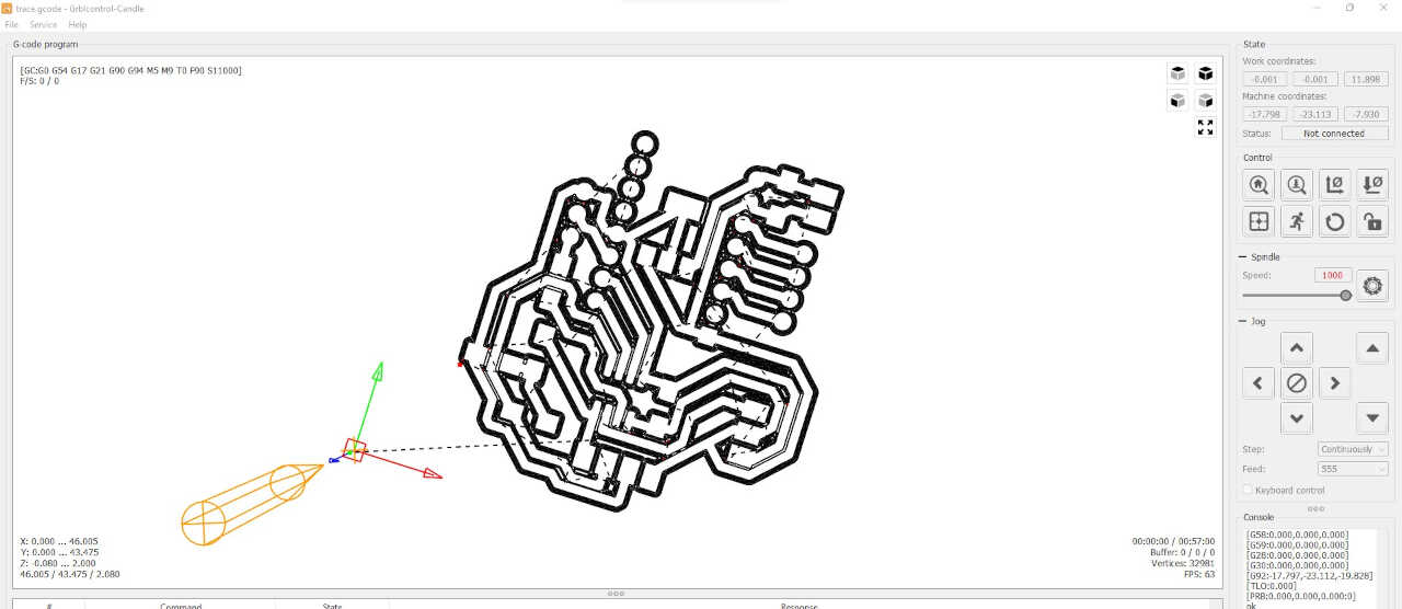
The design of the board finished, we go on fatcam to generate the gcode for the cnc
- Flatcam
For the flatcam settings I use the same settings I used in week 7 on Electronics Design.
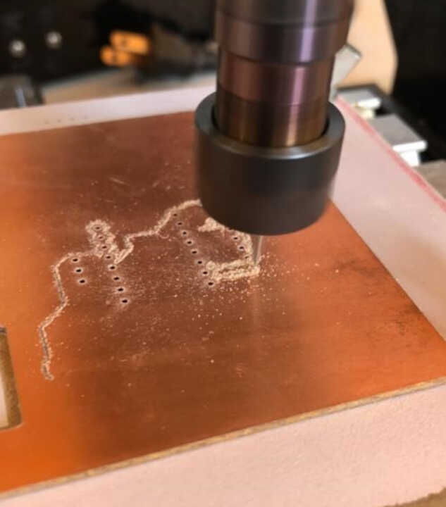
- mini CNC for milling
We are now at the step of milling the pcb
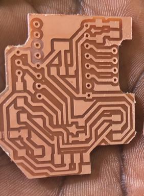
- Soldering
The milling is finished, it’s time to solder the electronic components on it. the image below shows the list of components that will be used in the pcb.
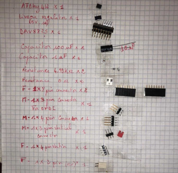
The soldering of the board is finished. We can see all the components from the list above that are all soldered on the board.
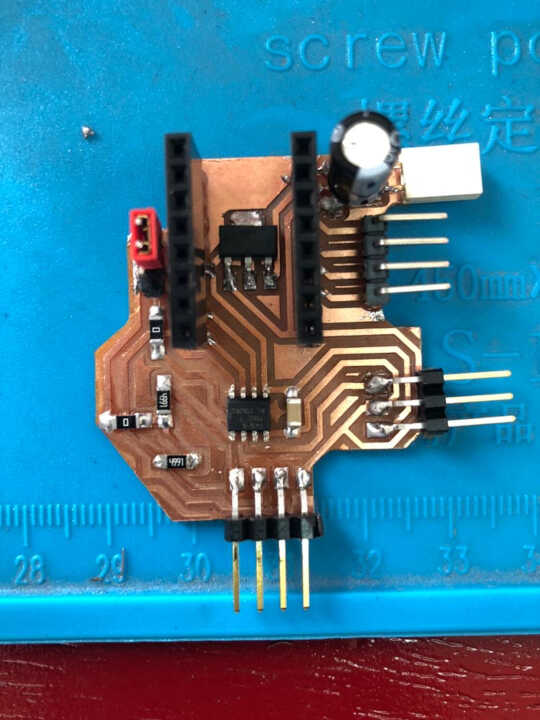
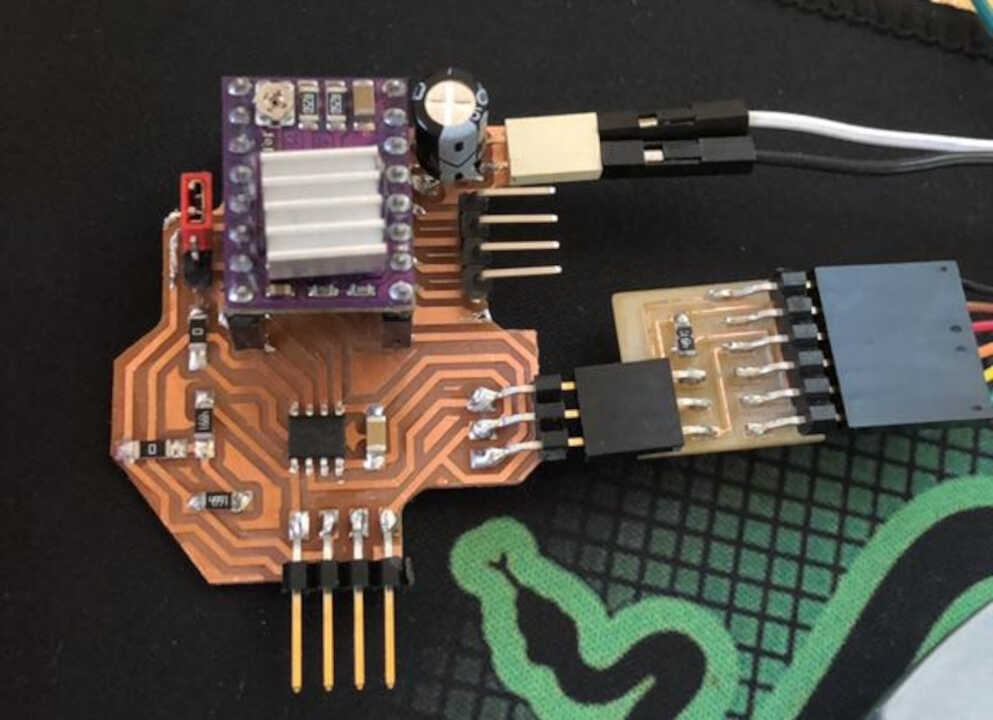
We can now plug in the driver, the power supply and program the board.
Programming
Before starting to program let’s take care to select the type of board to use by going to Tools > Boards > MegaTinyCore > ATtiny 412/402/212/202 and go select the ATtiny 412 chip in Tools>Chip
Finally we select the port of the board and we can now write and upload our program
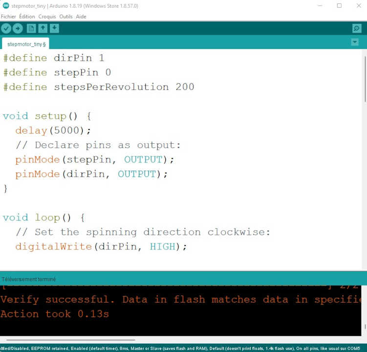
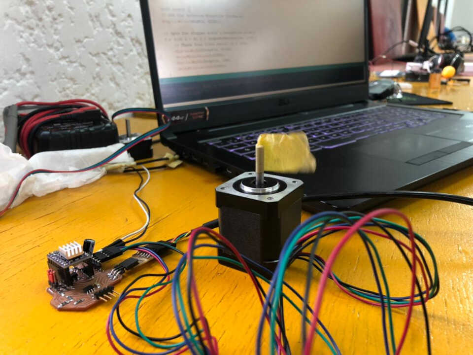
Here is what the program looks like to run my stepper motor.
In short, this program turns the motor in the first time by one turn in each direction and in the second time, the motor makes 5 turns in each direction with more speed than the first time.
    #define dirPin 1
    #define stepPin 0
    #define stepsPerRevolution 200

    void setup() {
    delay(5000);
    // Declare pins as output:
    pinMode(stepPin, OUTPUT);
    pinMode(dirPin, OUTPUT);
    }

    void loop() {
    // Set the spinning direction clockwise:
    digitalWrite(dirPin, HIGH);

    // Spin the stepper motor 1 revolution slowly:
    for (int i = 0; i < stepsPerRevolution; i++) {
        // These four lines result in 1 step:
        digitalWrite(stepPin, HIGH);
        delayMicroseconds(2000);
        digitalWrite(stepPin, LOW);
        delayMicroseconds(2000);
    }

    delay(1000);

    // Set the spinning direction counterclockwise:
    digitalWrite(dirPin, LOW);

    // Spin the stepper motor 1 revolution quickly:
    for (int i = 0; i < stepsPerRevolution; i++) {
        // These four lines result in 1 step:
        digitalWrite(stepPin, HIGH);
        delayMicroseconds(1000);
        digitalWrite(stepPin, LOW);
        delayMicroseconds(1000);
    }

    delay(1000);

    // Set the spinning direction clockwise:
    digitalWrite(dirPin, HIGH);

    // Spin the stepper motor 5 revolutions fast:
    for (int i = 0; i < 5 * stepsPerRevolution; i++) {
        // These four lines result in 1 step:
        digitalWrite(stepPin, HIGH);
        delayMicroseconds(500);
        digitalWrite(stepPin, LOW);
        delayMicroseconds(500);
    }

    delay(1000);

    // Set the spinning direction counterclockwise:
    digitalWrite(dirPin, LOW);

    //Spin the stepper motor 5 revolutions fast:
    for (int i = 0; i < 5 * stepsPerRevolution; i++) {
        // These four lines result in 1 step:
        digitalWrite(stepPin, HIGH);
        delayMicroseconds(500);
        digitalWrite(stepPin, LOW);
        delayMicroseconds(500);
    }

    delay(1000);
    }
File
What went wrong/What went wel
For this mission, everything went well overall. By dint of designing electronic boards, you become an expert.😃