8. Computer controlled machining
Large format milling and construction
Assignment Overview
For this week’s assignment, we were tasked with designing, milling, and constructing a large object using a large format CNC machine. The purpose of the assignment was to learn how to use large format CNC machines and how to design for it. As usual, there was a group assignment related to characterising the CNC machine, and an individual assignment, which involved designing and constructing your own piece. Details regarding the requirements of the assignments as well as the learning outcomes are given below.
Group assignment:
- Complete your lab’s safety training
- Test runout, alignment, speeds, feeds, and toolpaths for your machine
- Document your work to the group work page and reflect on your individual page what you learned.
Individual project
- Make (design+mill+assemble) something big
Learning outcomes
- Demonstrate 2D design development for CNC production
- Describe workflows for CNC production
Group assignment
Equipment Details
The large format CNC machine that we use in our shop is called 1325 CNC Router Woodworking Machine.
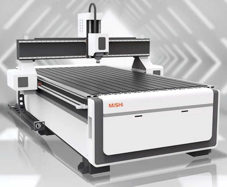
| 1325 CNC Router Woodworking Machine | |
|---|---|
| Machine Type | 1325 Single Head CNC Router Woodworking Machine |
| Table Size | 1300*2500mm |
| Work Plan | 13002500200mm |
| Maximum Empty Travel Speed | 17000mm/min |
| Working Speed | 15000mm/min |
| Spindle Power | 3.2 kw JST Water Cooling spindle |
| Spindle Speed | 0-24000rmp |
| Motor | Leadshine 860 |
| Operating Voltage | AC220V/380V, 50HZ |
| Run Command | G Code |
| Operating System | DSP/NC Studio |
| Support Software | Type 3,Artcam,JD |
| Assist | Dust Hood, Dust Tube |
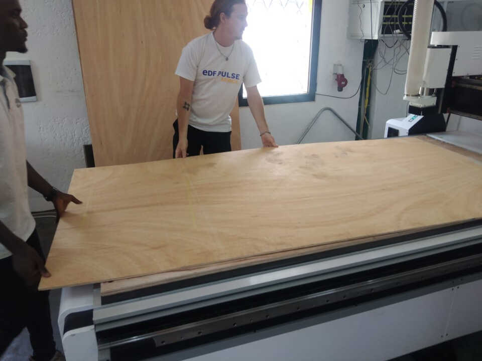
Preparing for the cnc
- Fixing the sacrificial surface
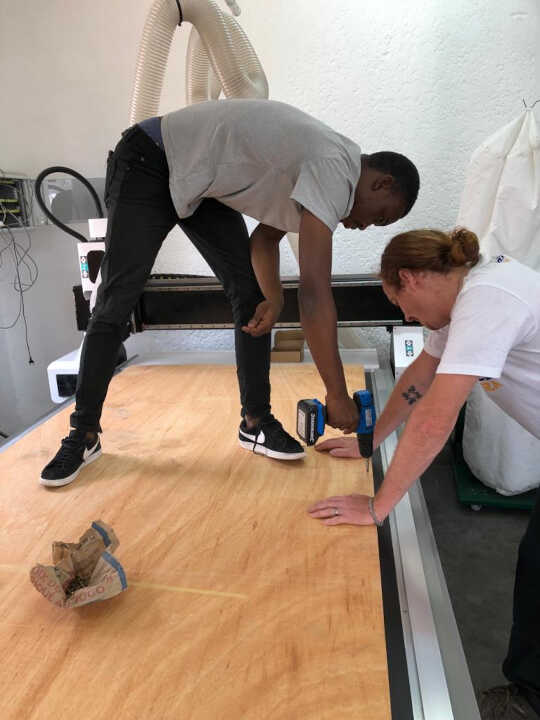
we had to load the plywood and secure it to the sacrificial layer of the machine
You can see here that we attach the plywood to the bed with a hand drill and screws. The reason for this is that we want the work piece to move little or not at all.
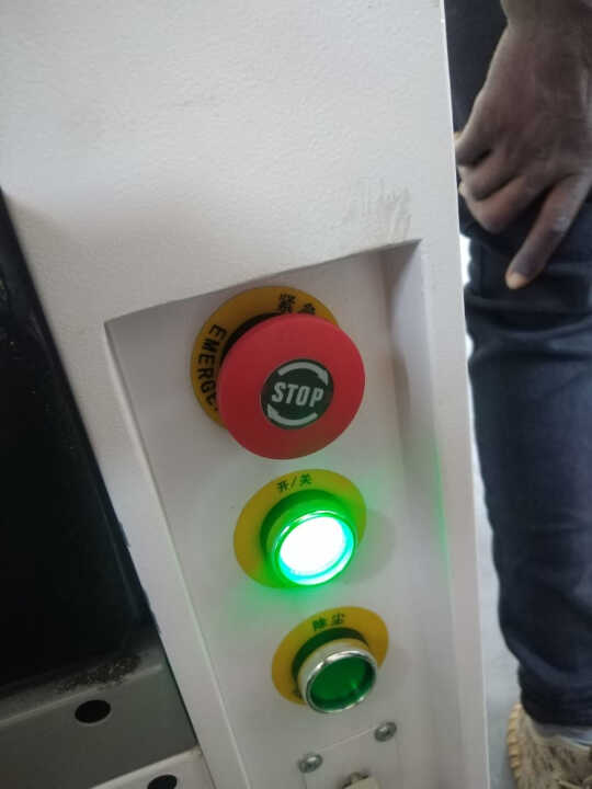
- Turn on the CNC
The next thing is we turned the machine on. In the picture below, the button with light on is the power switch of the CNC machine and the green button below it is the power button for the vacuum machine and above it all is the emergency stop switch.
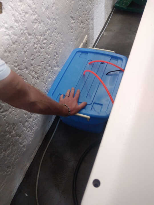
- Check the pomp (feel the vibration)
The next thing is to check if the water pump is in operation. We touched the water reservoir to feel the vibration of the water pump admist the noise of the CNC machine.
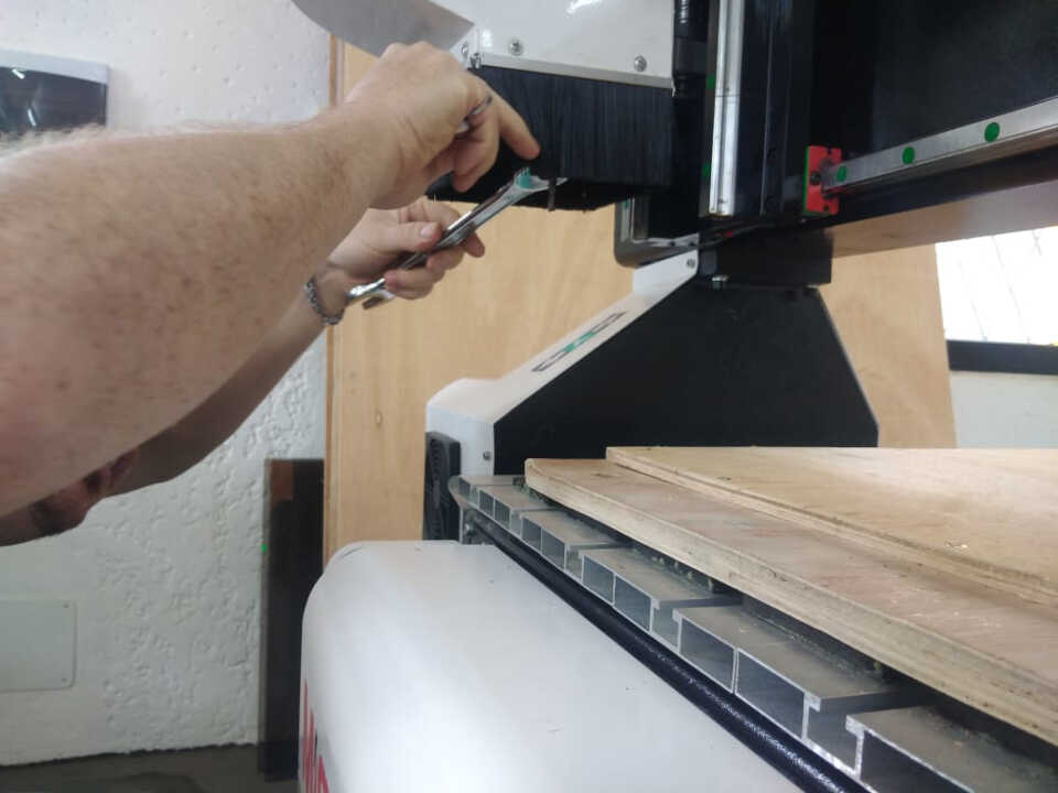
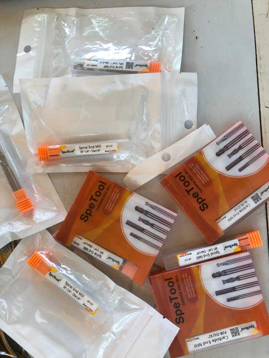
- Put the bit
After all the necesaary checks, the tool bit we will be working with was loaded. A flat end up cut tool bit was used in all our milling and routing operations.
| Specifications | of the tool bit |
|---|---|
| flute/cut diameter | 6.35mm |
| flute height | 33mm |
| shank diameter | 6.35mm |
| shank length | 43mm |
CNC Software
Open the NCstudio software
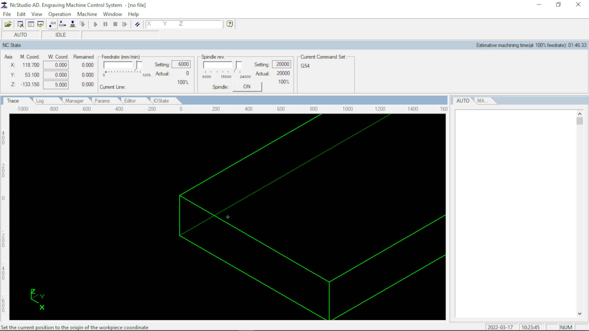
Manually move the tool stock by using the manual JOG buttons on the right side of the apd window.
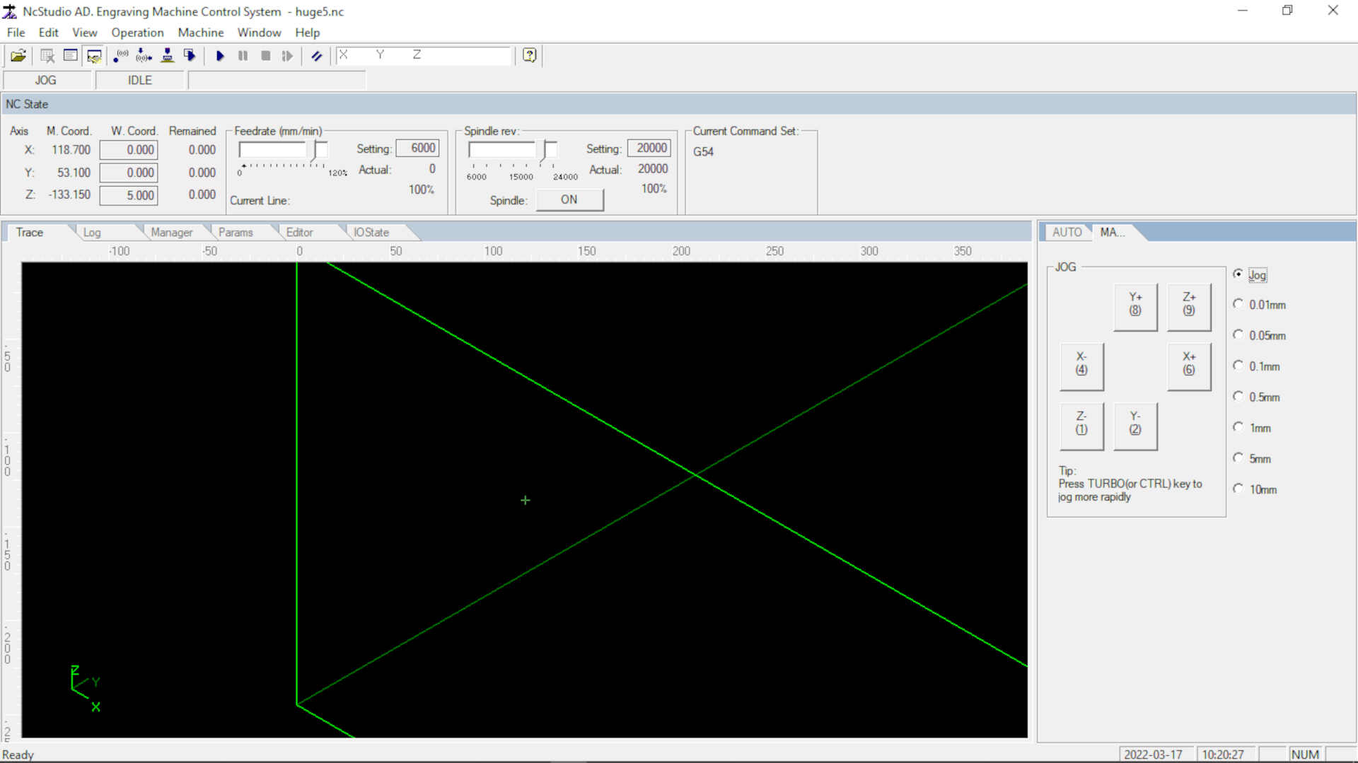
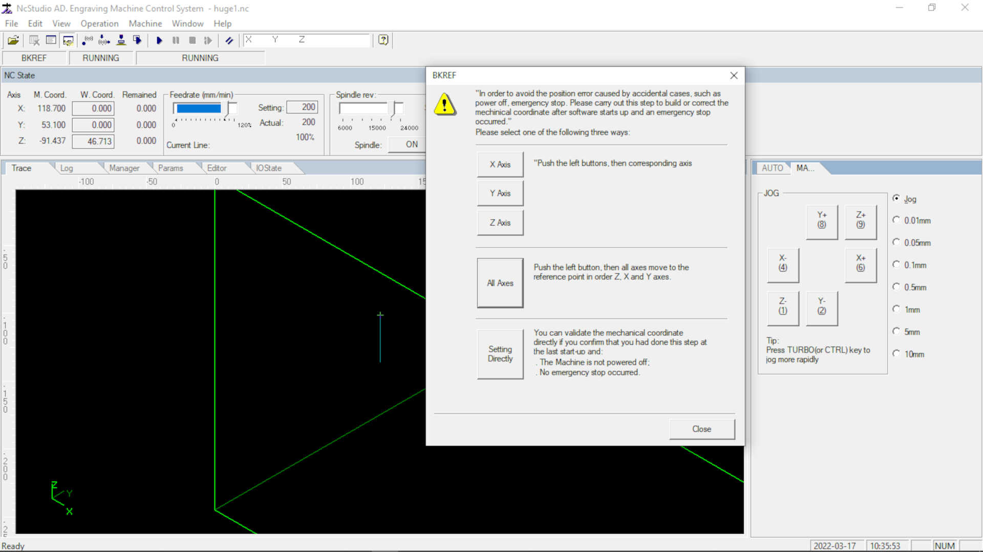
Click operation Click on move to refference point
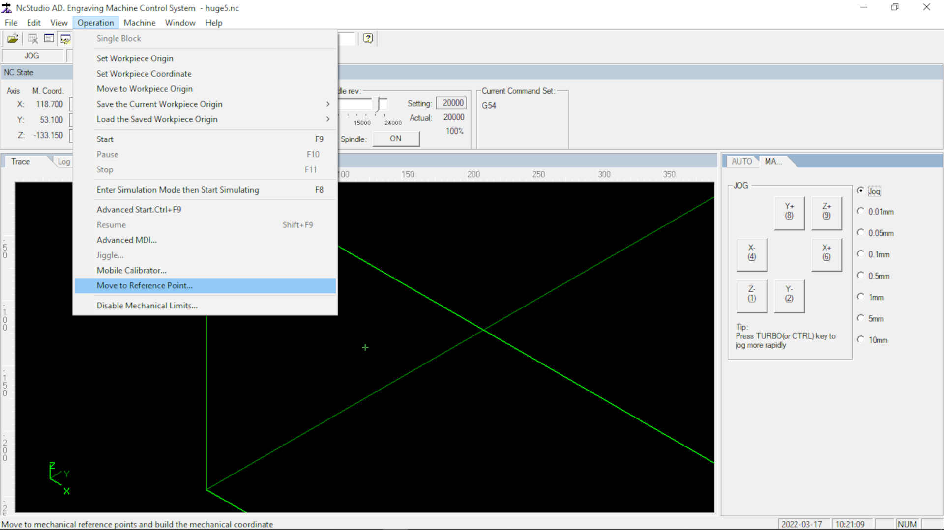
Click on all axes, this should move the tool stock and the carriage to the machine’s home point.
Move to your zero point using the manual jog controls.
Zero all axes by clicking W.Coord on the tool bar of the software
Press f7 to accept and check zero point you set. (ps. the tool should move 50mm above the bed)
Once your origin has been set, you can move forward to load your file and start your operations.
Completing our lab’s safety training
For the safety training, we were required to put on safety personal protective equipment like:
- Safety glasses to protect our eyes
- Ear plugs to block loud noises
- leather gloves to prevent splinters when handling the wood pieces.
- make sure the blower and water pump were working to avoid any fire hazards.
After learning the safety precautions to take, we will perform the following tests:
- Testing runout
- Testing alignment
- Testing speeds and feeds
- Testing toolpaths and Create test fit pieces for joints
Testing runout
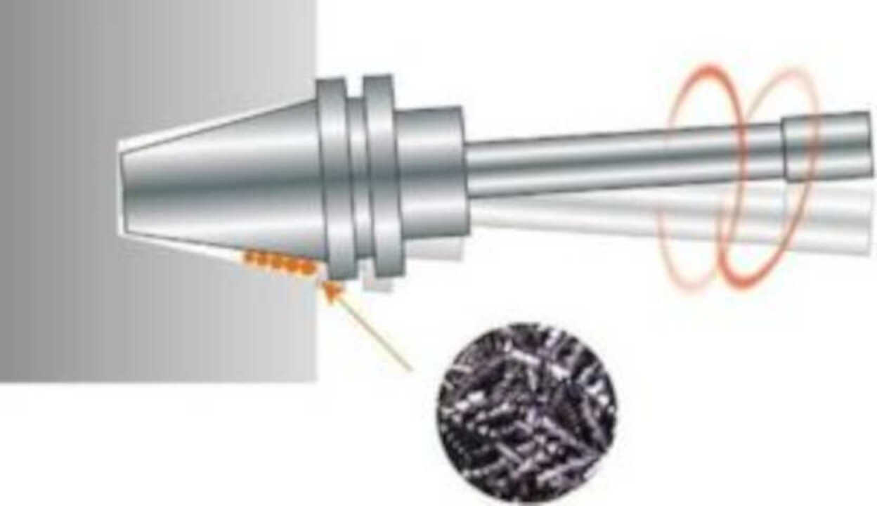
Runout occurs when the tool on a CNC machine runs off of the correct axis, increasing the potential for errors to occur throughout the milling process and drastically reducing the expected lifetime of the tool. There are two types of runout: axial runout and radial runout:
Runout is important to avoid since it can decrease tool life and can increase the chance of machining defective parts. Runount may result from excess debris, dirt, coolant that enters the spindle and interferes with the clamped tool, which often results in defective machinery parts or shortened tool life. There are several ways to mitigate tool runout, including using higher quality tool holders, performing frequent maintenance and cleaning on the bit, and decreasing the stickout of the bit.
- Axial Runout Axial runout is when the bit is not perfectly perpendicular to the surface you are attempting to cut. This can cause rotation in the bit that is not good for a cut. If you are using a flat end mill bit, normally you would like a perfectly vertical profile for your parts, but if there is any axial runout, that edge will not be perfectly straight. Below is an image that is a visual representation of axial runout.
- Radial Runout Radial runout occurs when the drill bit is not perfectly centered in the spindle. This can affect every sort of outline, whether it be interior or exterior. If it affects an interior outline, any sort of slot or interior cutout will be slightly larger than intended. This means that if something is meant to be snap fit, the slot will be too large and the joint will be too loose.
To test the Runout you have to use a sensitive dial gauge indicator, which its accuracy measured in 0.01 mm. fixed it to the table and the tip should touch the spindle.
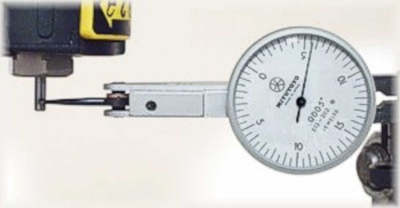
unfortunately we don’t have this device to do the test but the most important thing was to understand the concept.
Testing alignment
We tested the alignment of the machine by cutting a square and see if the tool cuts the square at right angles. We modeled the square on freecad with 10cm for the sides. The measurements taken after cutting are shown in the following pictures:
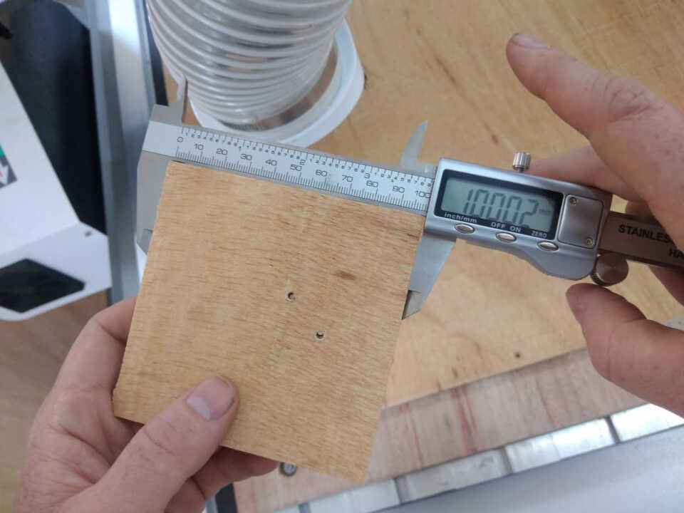
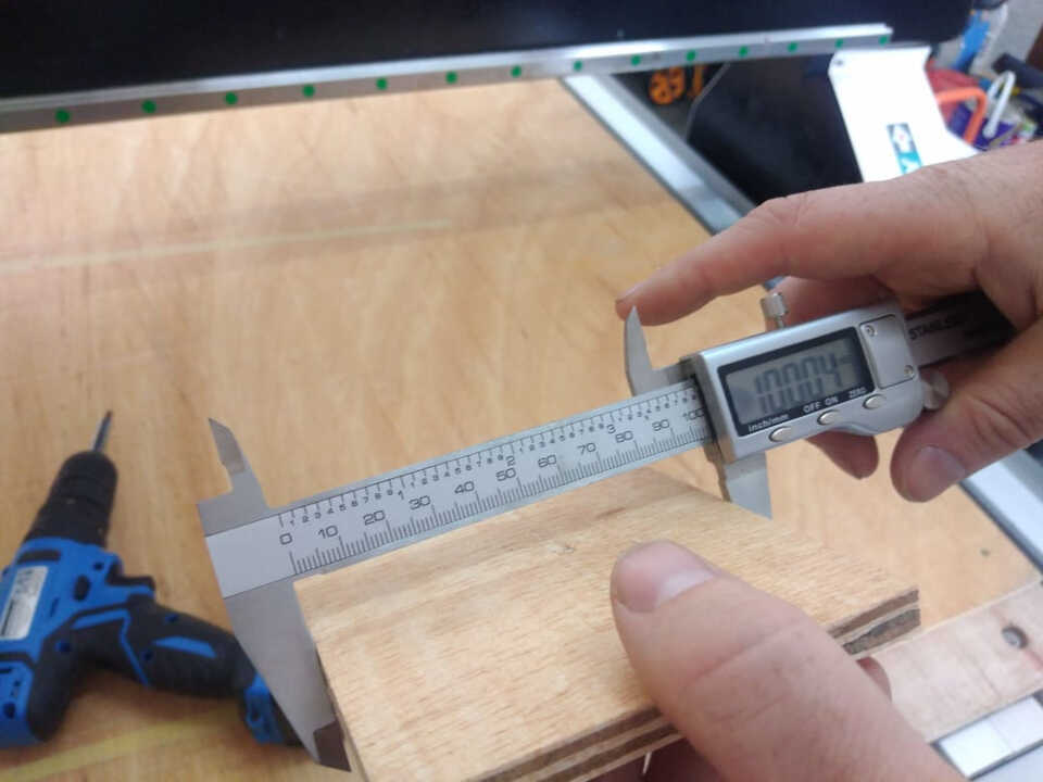
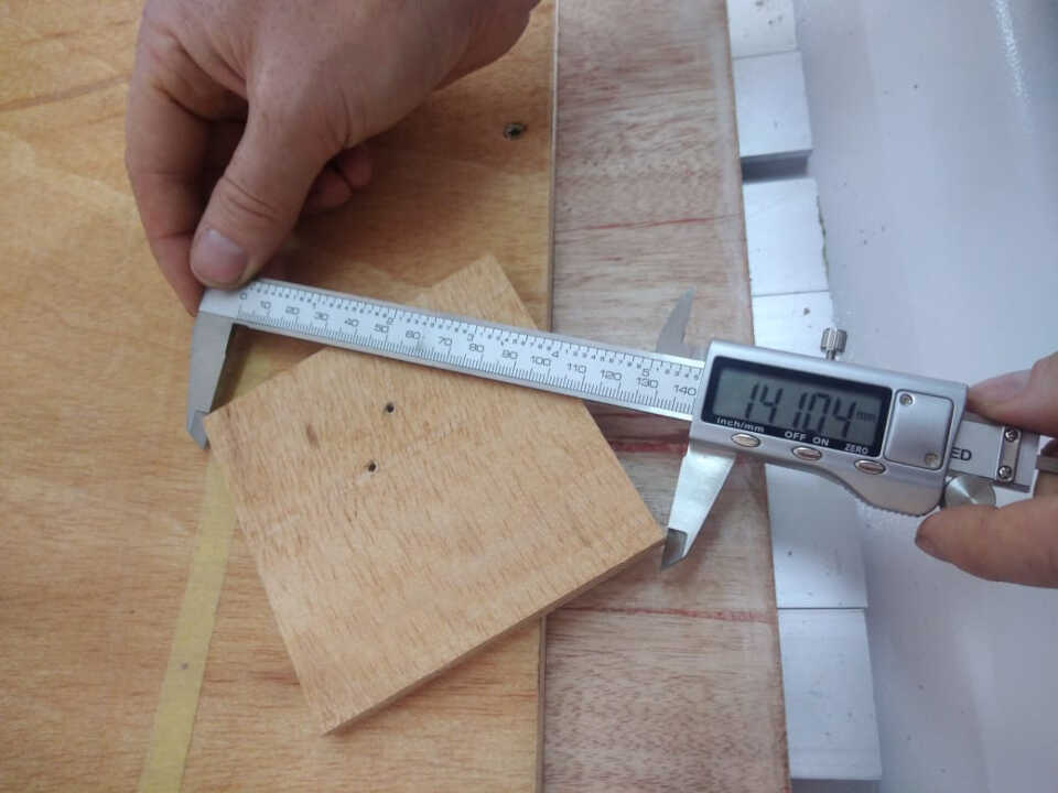
We note a variation of 0.02cm, which can be negligible for the continuation of our work
Testing speeds and feeds
Speeds and feeds are the cutting variables used in every milling operation and vary for each tool based on cutter diameter, operation, material, etc. {reference. With large format CNC machining, the speed and feed can be calculated knowing the chip load. the number of flutes on the bit, and the spindle RPM.
An easier method to determine speed and feed is using an online calculator such as the one given at this link here. An image of the calculator is shown below.
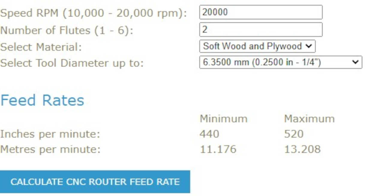
In our group assignment, we calculated and test the speed and feed using the calculator above for plywood with a 1/4” bit and a spindle speed of 20000 RPM.
Testing toolpaths and Create test fit pieces for joints
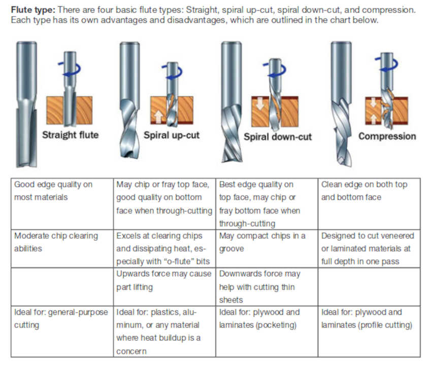
- Flute types
With our instructor Paul, we learned about different types of forests and their use cases.
(from ShopBot quick start guide): the one we are using is a 1/4” spiral down-cut
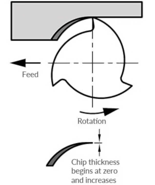
- Climb Milling/Conventional Milling {reference}
We also learned to understand the different properties compared to conventional milling and climb milling.
Conventional Milling
- Chip width starts from zero and increases which causes more heat to diffuse into
 the workpiece and produces work hardening
- Tool rubs more at the beginning of the cut causing faster tool wear and decreases
 tool life
- Chips are carried upward by the tooth and fall in front of cutter creating a marred finish
 and re-cutting of chips
- Upwards forces created in horizontal milling* tend to lift the workpiece, more intricate
and expansive work holdings are needed to lessen the lift created*
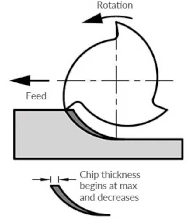
Climb Milling
- hip width starts from maximum and decreases so heat generated will more likely transfer to the chip
- Creates cleaner shear plane which causes the tool to rub less and increases tool life
- Chips are removed behind the cutter which reduces the chance of recutting
- Downwards forces in horizontal milling is created that helps hold the workpiece down, less complex
work holdings are need when coupled with these forces
- Horizontal milling is when the center line of the tool is parallel to the work piece
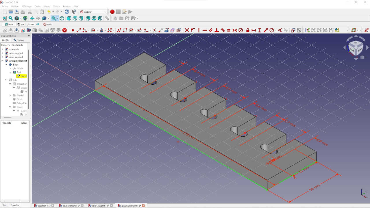
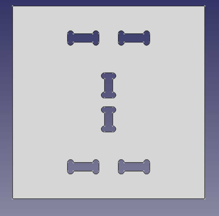
To do the test of the toolpath we decided to do two things at once by doing the test for the pressfit at the same time. To check the pressfit we have designed a piece with different lace measurements on freecad.
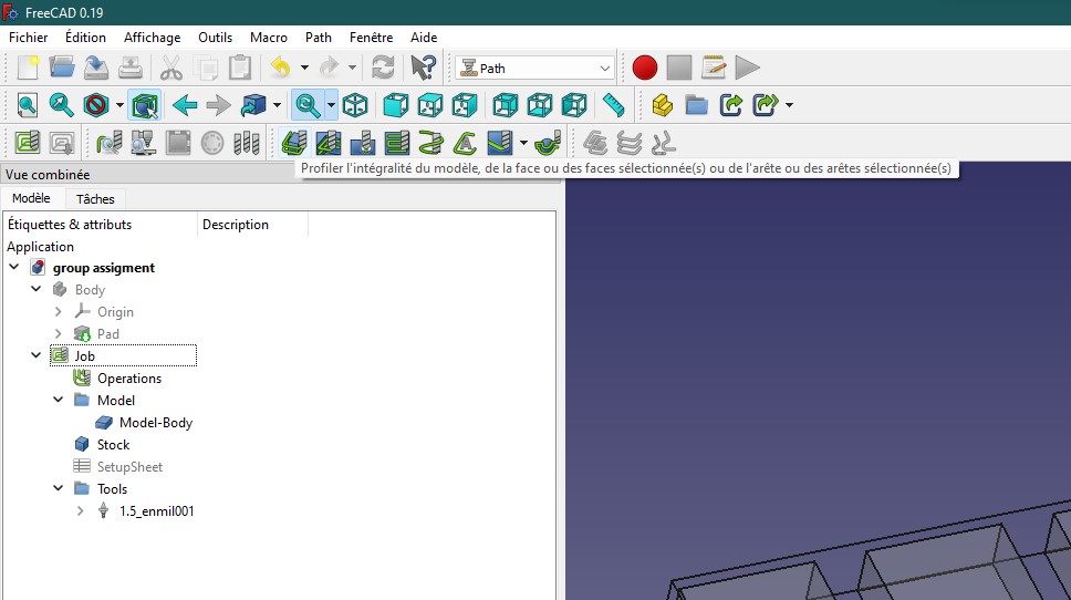
After modeling my object, I go to the Paths workshop as shown in the image below.
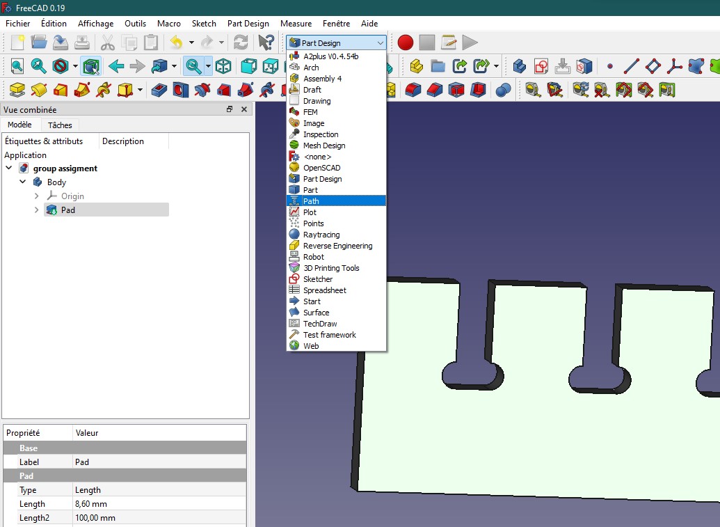
In the Path workshop, we can see a green icon in the toolbar. So we click on this icon.
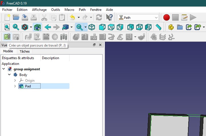
A Create Job window opens where we select the name of our object.
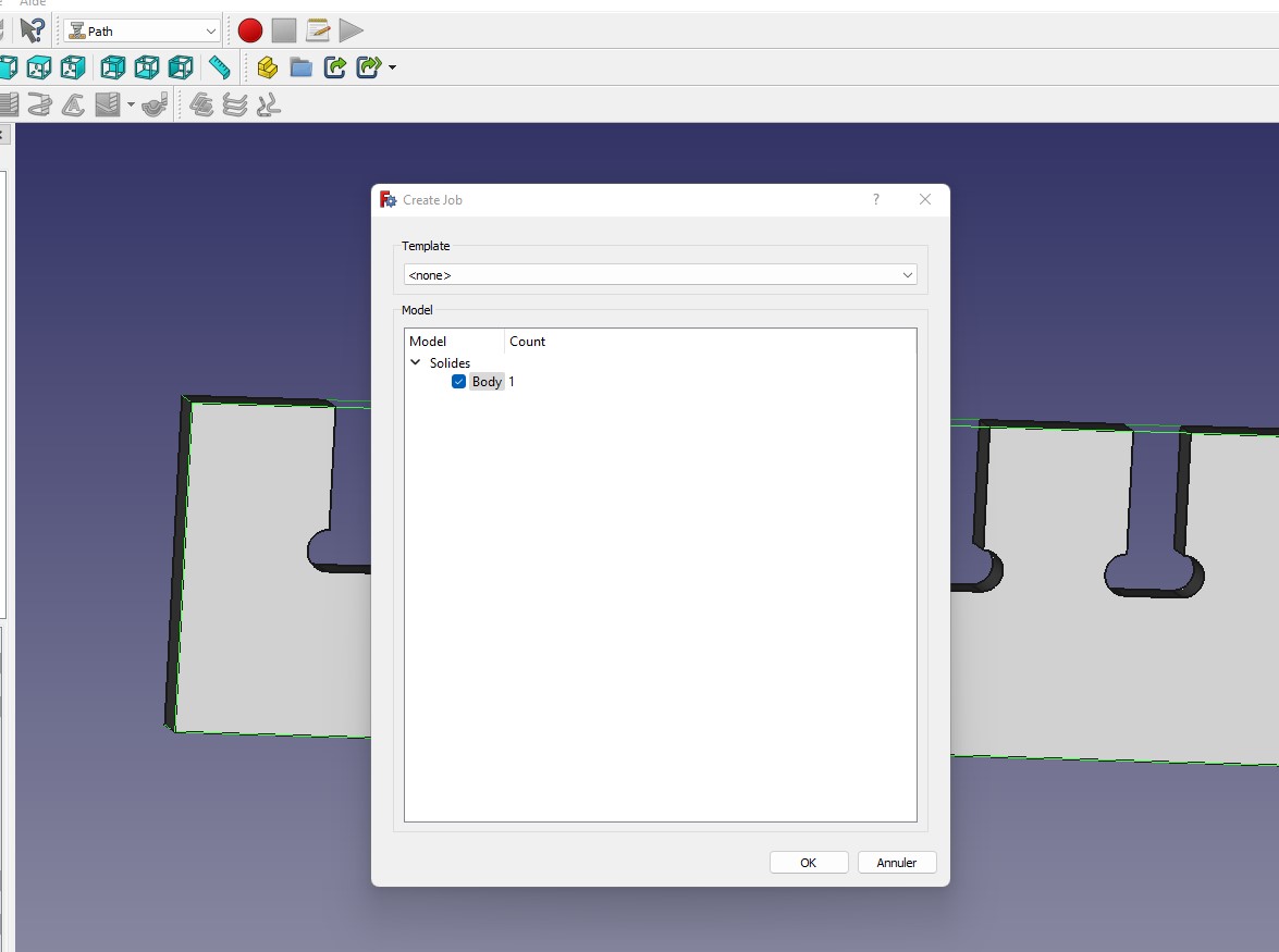
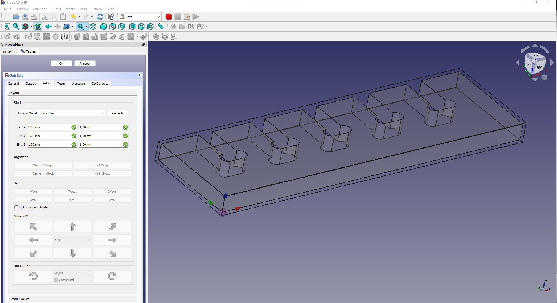
On the left side of the taskbar, we have the Job Edit window. Here are the parameters used in the Setup onget window
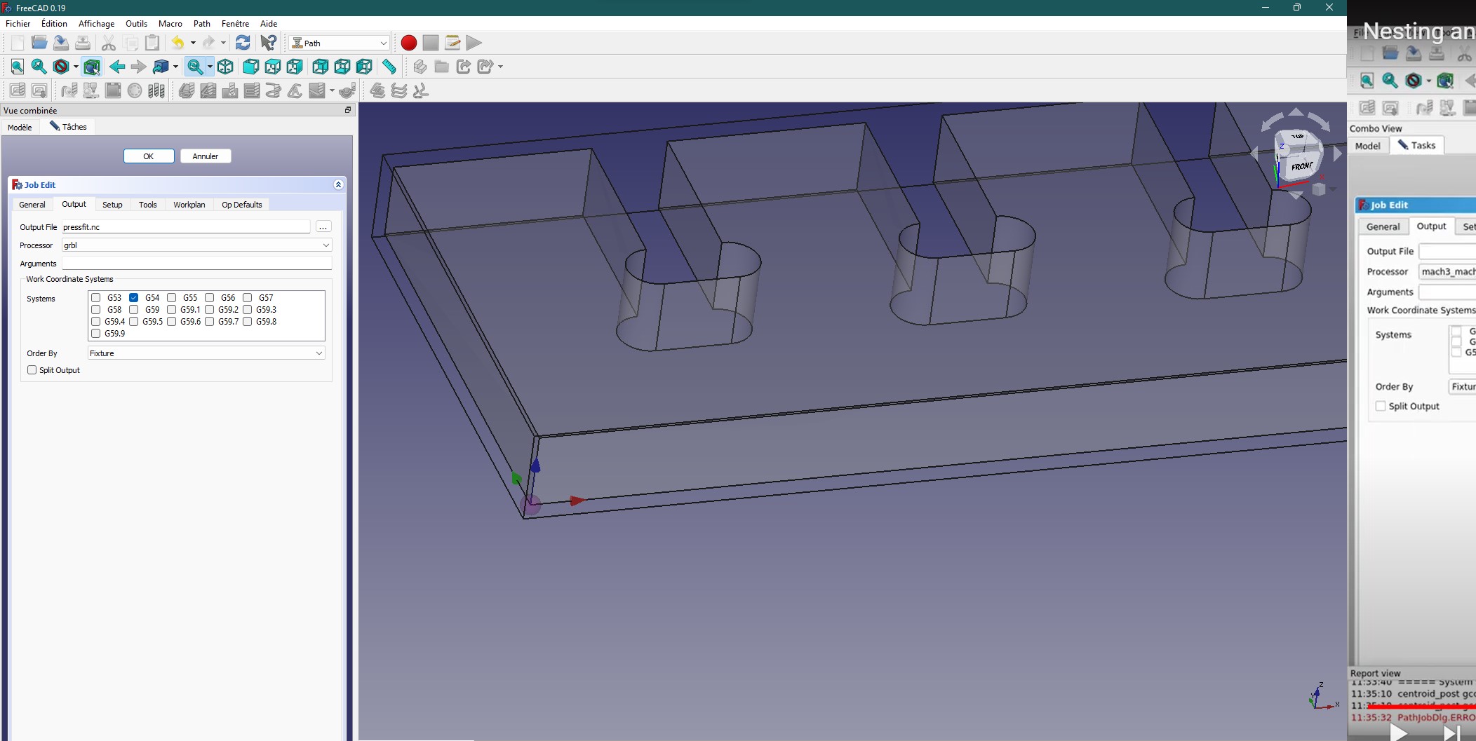
We move to the Output tab where we indicate where the gcode file will be saved and also select the type of processor used by our CNC.
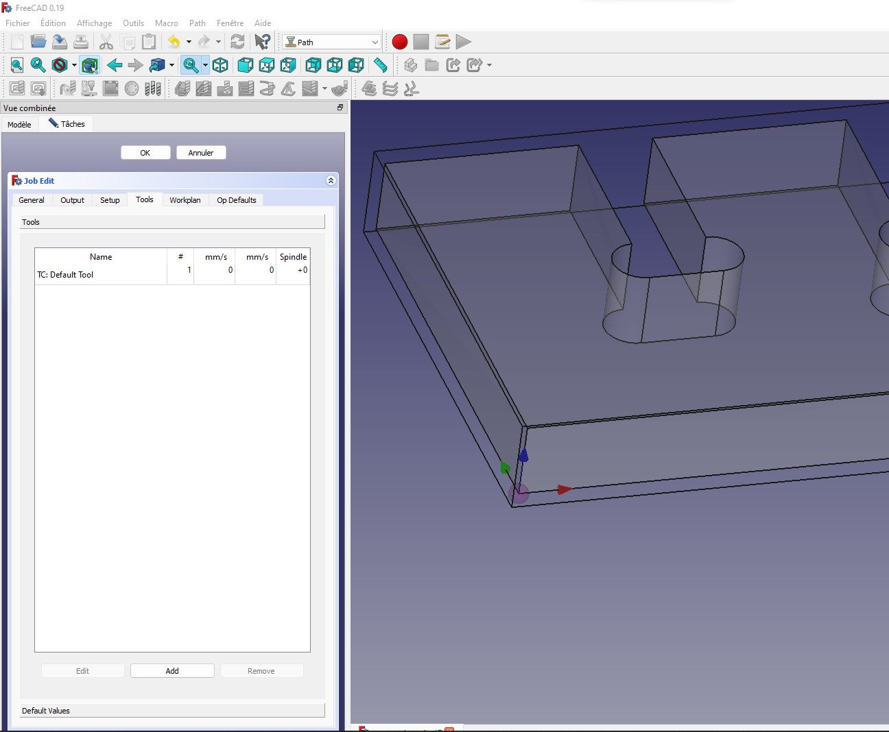
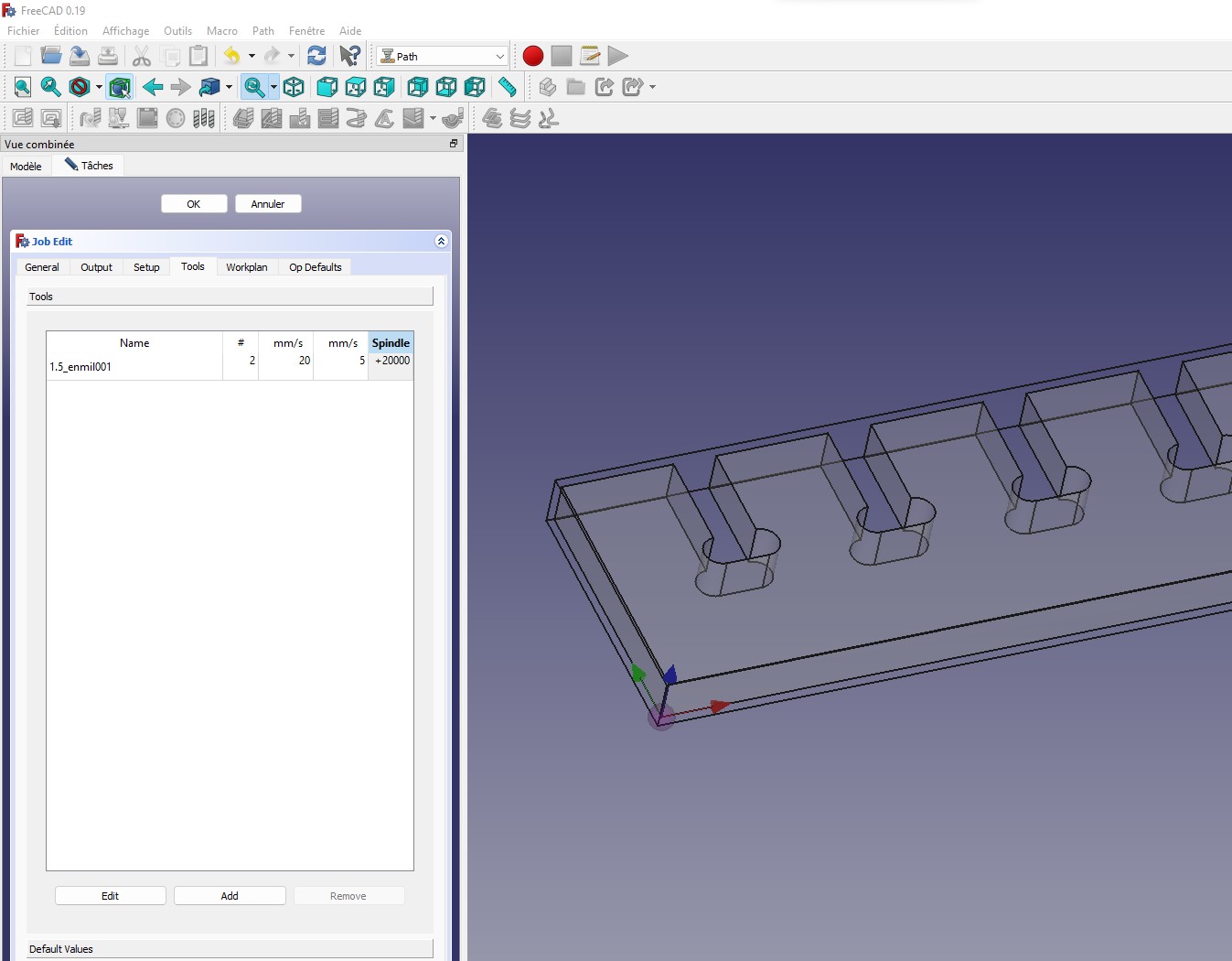
In the Tools tab we select the type of bit that will be used by our CNC.
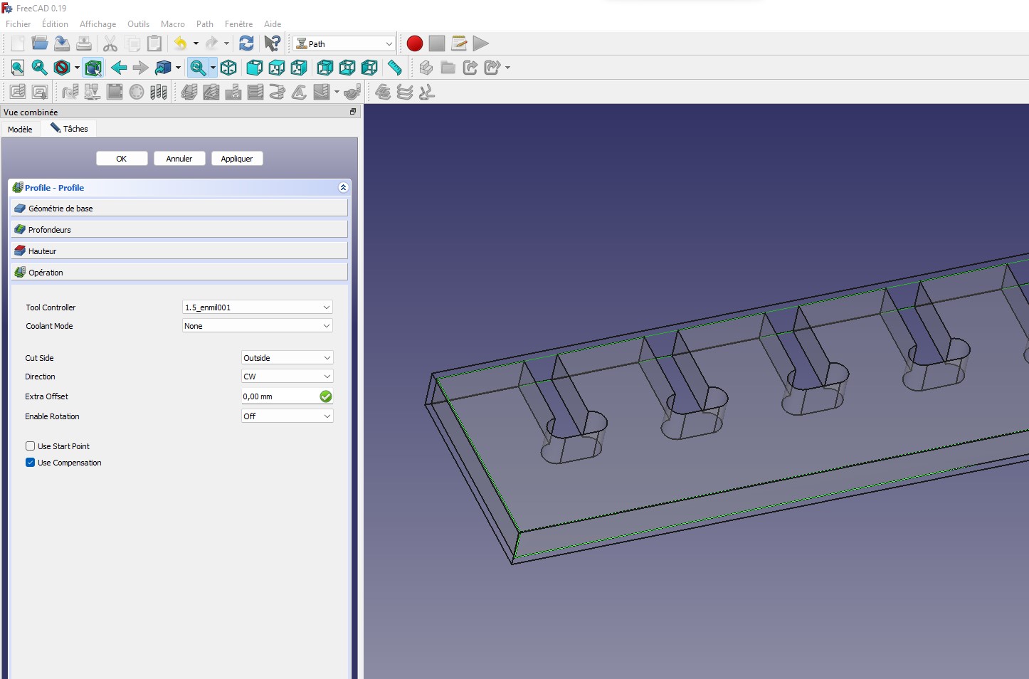
In this step we click the icon where the comment is located to set the profile.
The image below shows the settings in the Operation section of the profile.
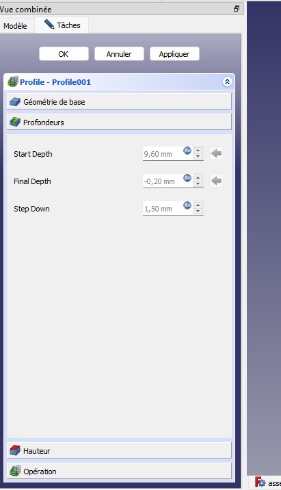
The image below shows the settings for the Depth section of the Profile.
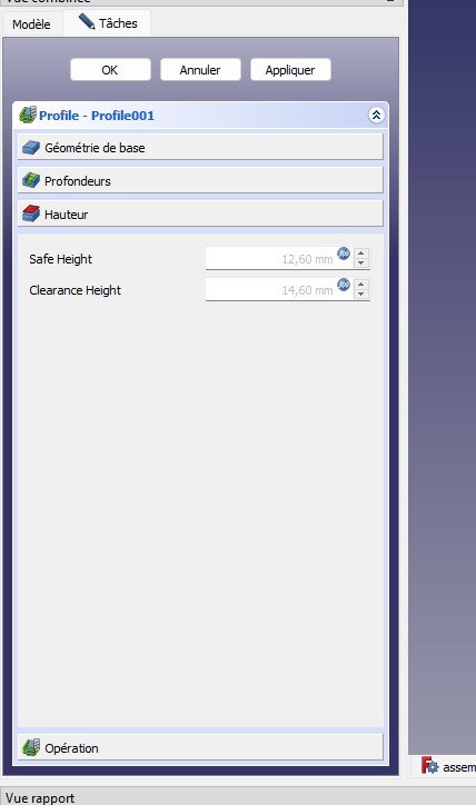
The image below shows the settings for the Height section of the Profile.
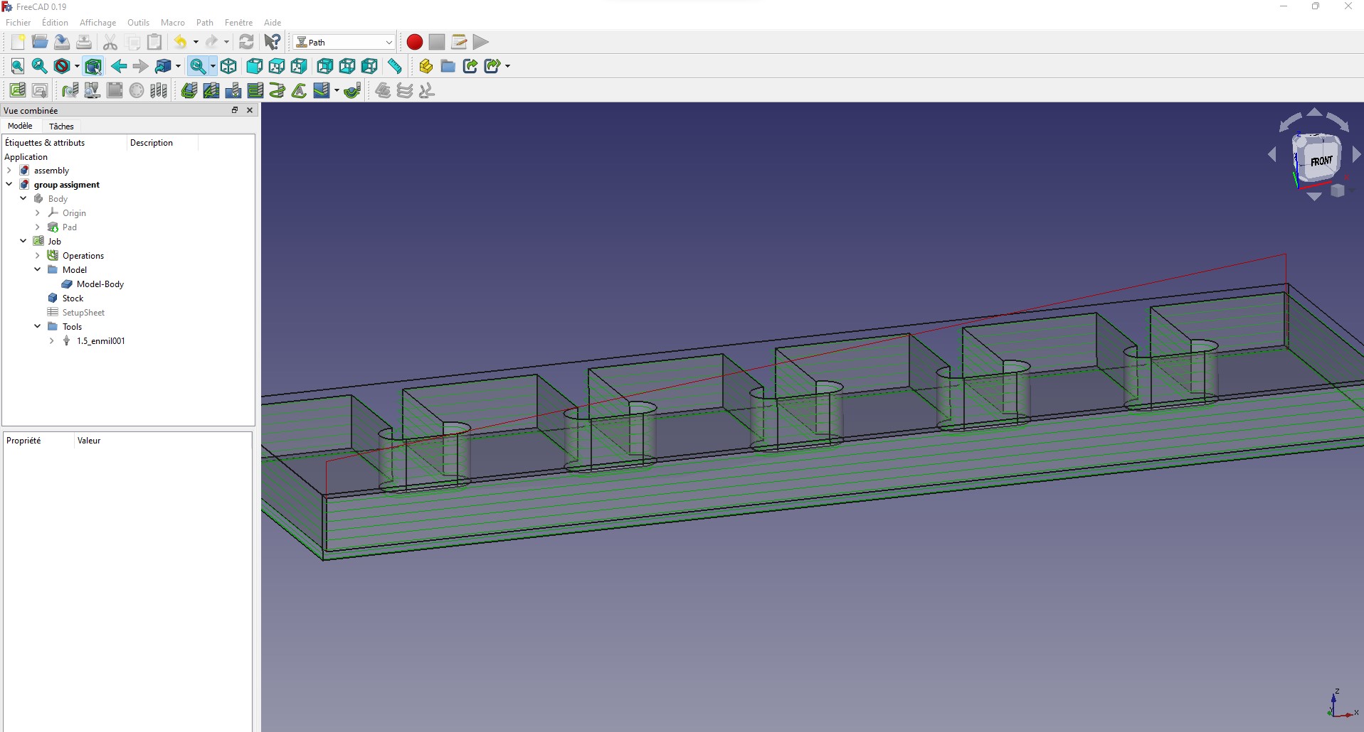
we now notice several green lines around our object. these lines show us the trajectory of the milling machine’s bit.
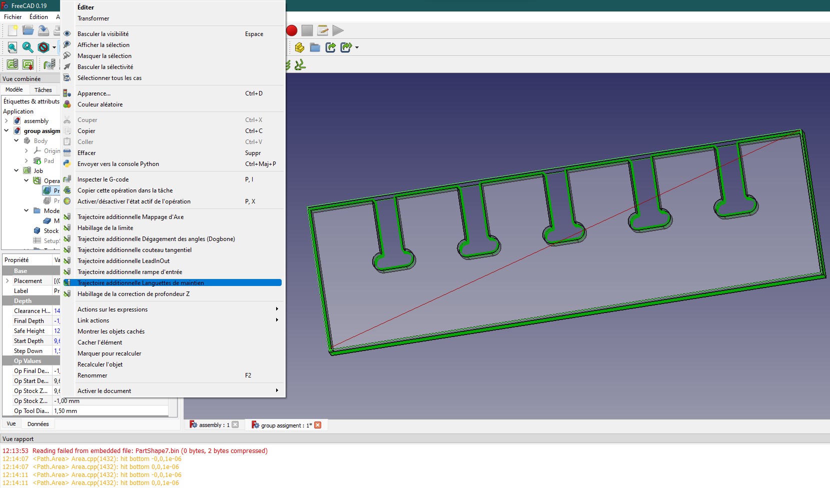
It is important at this point to put tabs on our object that will allow it to remain stationary during the entire milling process. To do this, we right-click on the profile in Freecad’s combined view. In the window that opens, we click on Additional path Holding tabs.
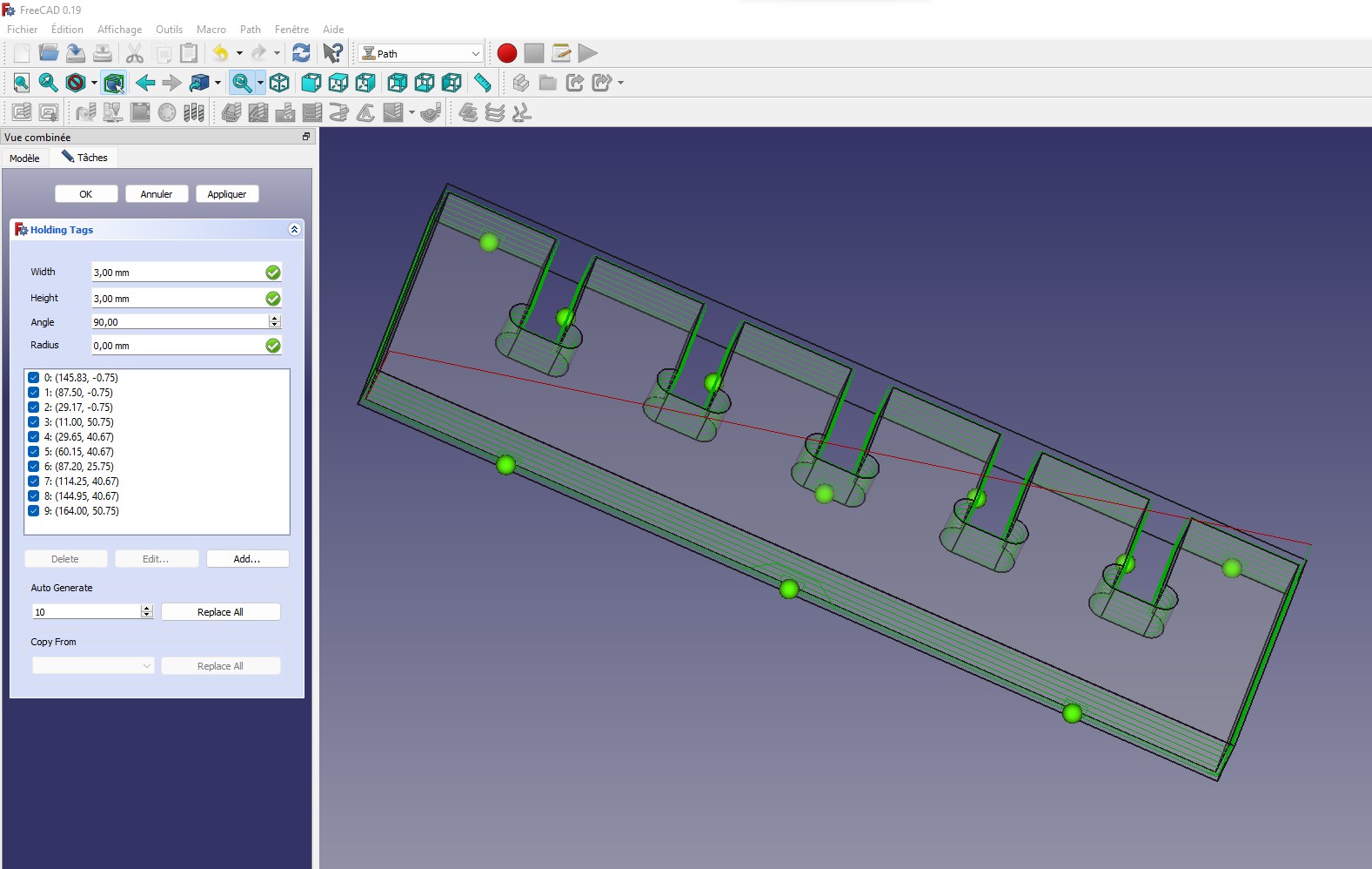
At this level, you can see below that by selecting the number of tabs we want, they are generated automatically on the object. You can also see the parameters used for the tabs.
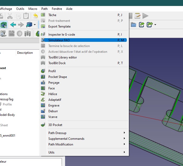
We have completed all the essential settings to be made. Before saving the file, we will simulate the milling of the object. To start the simulation we go to the Path window and in the window that opens we click on CAM Simulator.
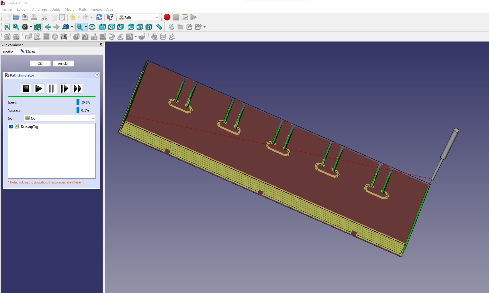
By clicking on the Play button, we can see how the milling will be done.
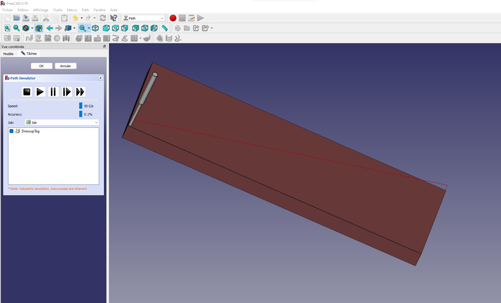
Here you can see the result at the end of the simulation
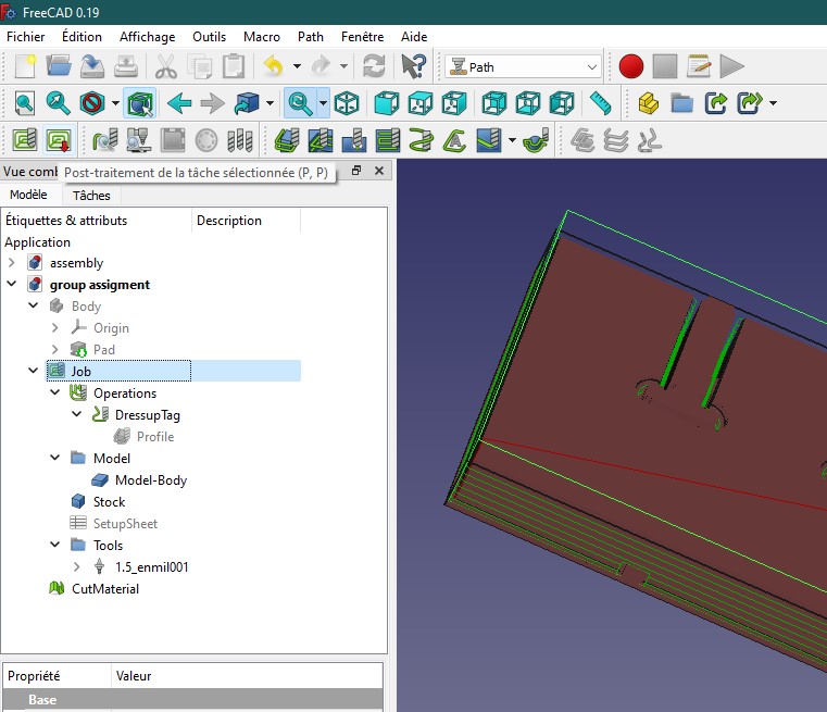
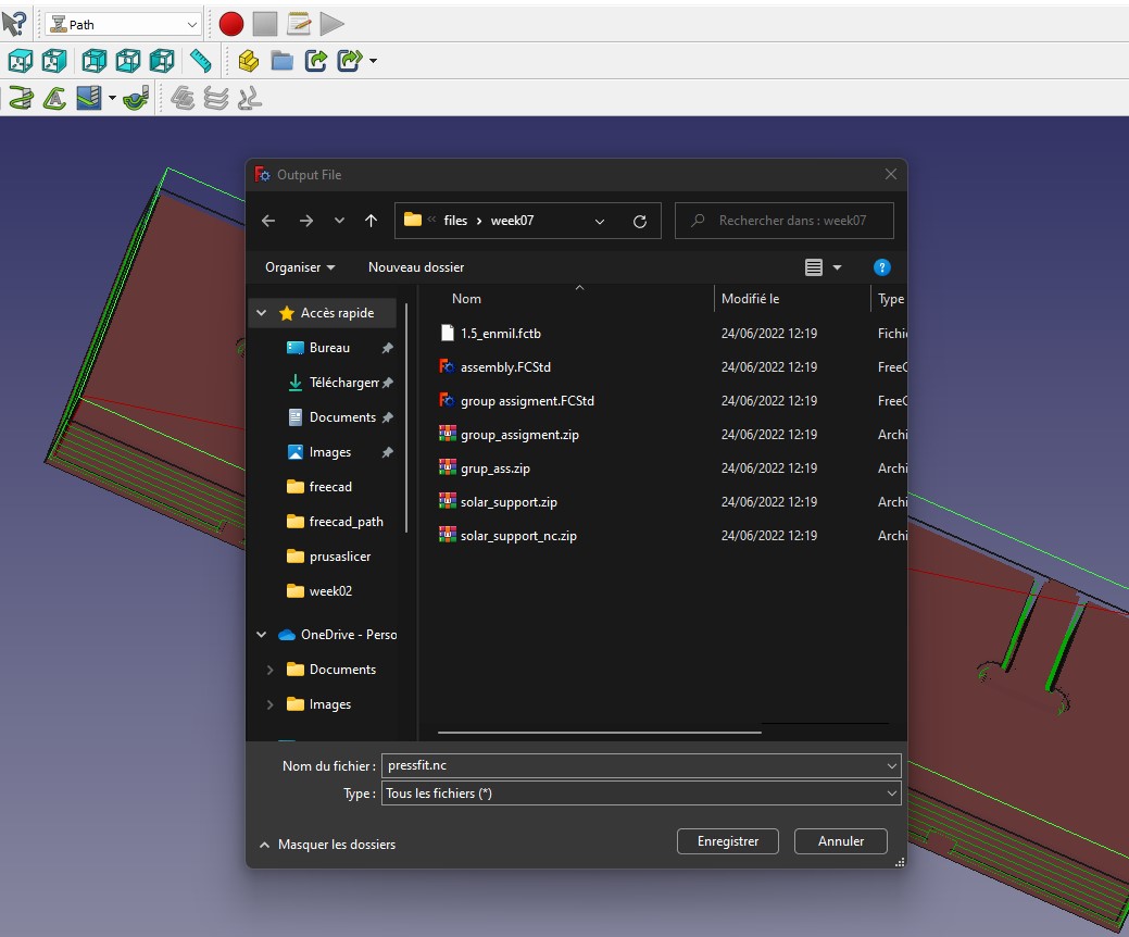
Now we will create the gcode file that will be used in the cnc software. To create it, we need to click on the green icon with a red arrow pointing down. You can see it in the image below.
We save the file in the directory that interests us.
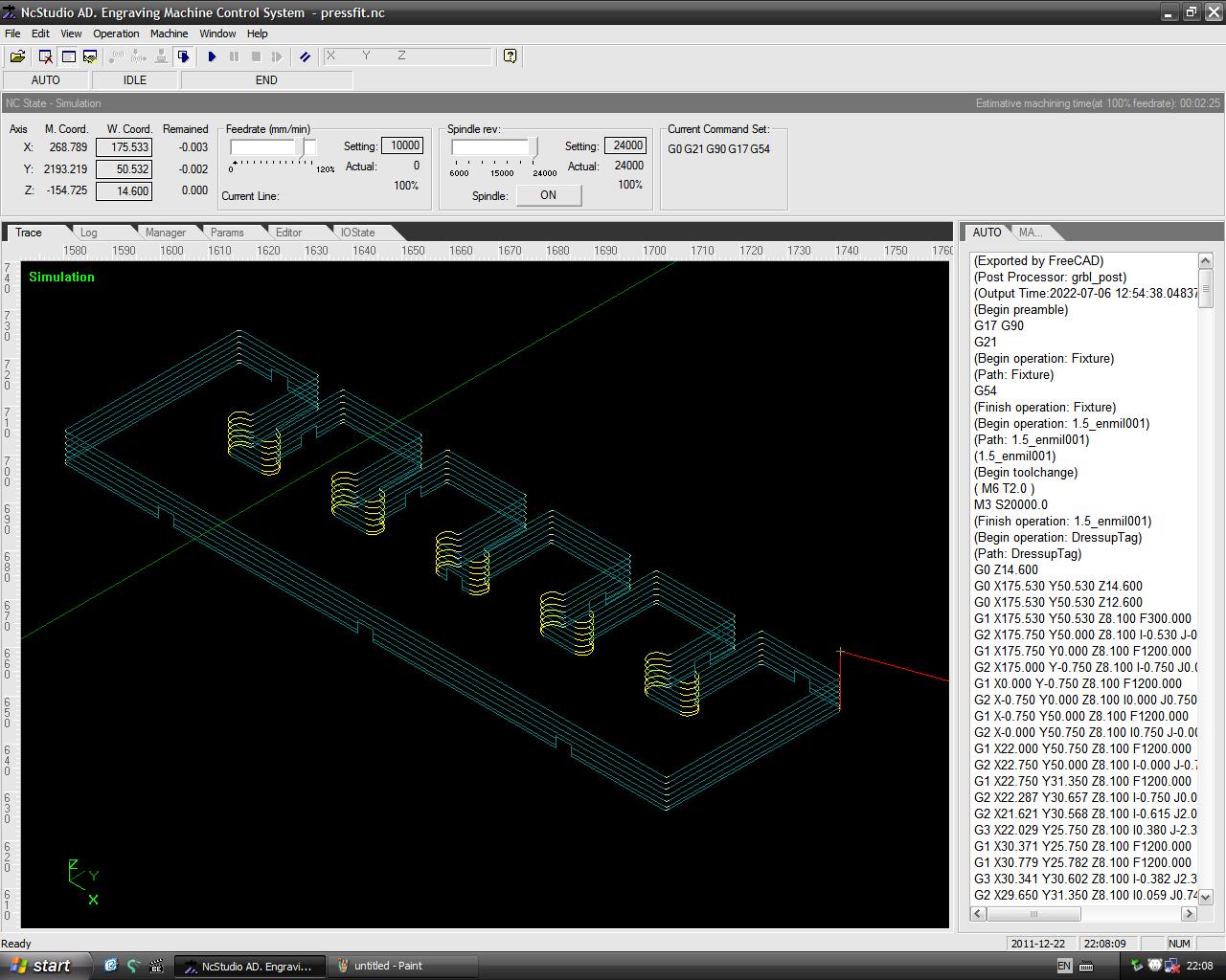
Now we switch to the NcStudio software, in which we open the file created by Freecad. Then we make a simulation of the cutting before starting the cnc.
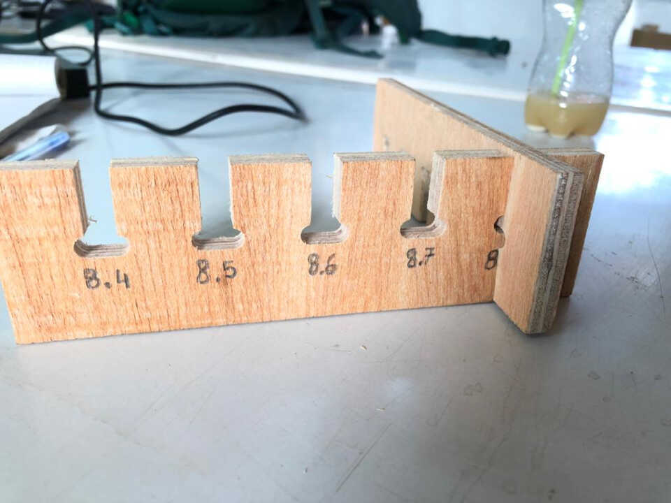
After milling, here is the result.
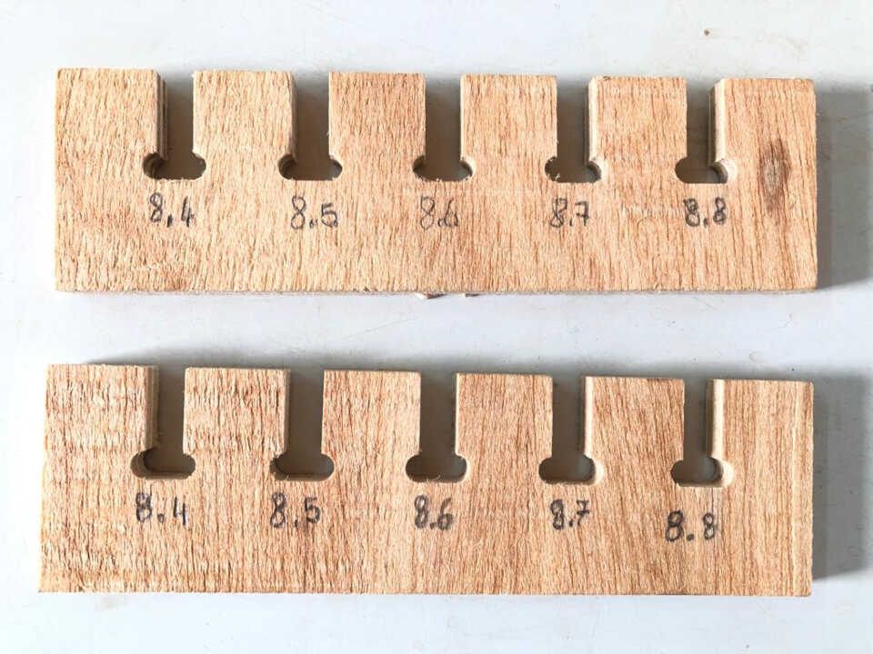
the result shows that the ideal dimension for the joints is 8.8 mm
Individual project
In this section, I will present the workflow and methodology used to complete the requirements for the individual assignment, which were to design, cut, and construct a large format piece that is on the order of 1 m in scale.
The concept
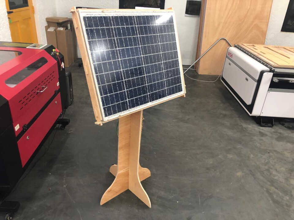
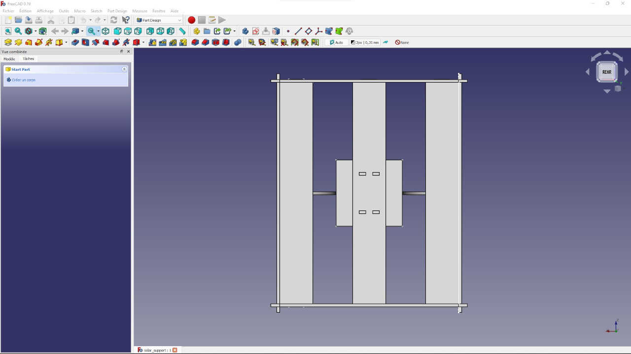
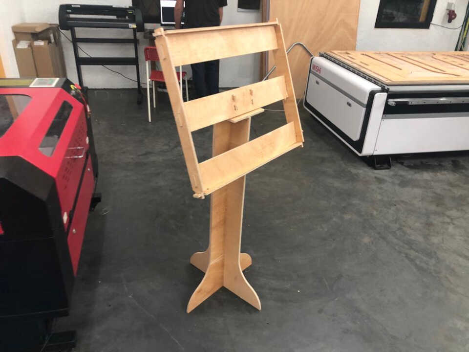
My idea is to reproduce in real size my personal assignment of the week 3 concerning the computer controlled cutting. It is a support for solar panel which is part of my final project.
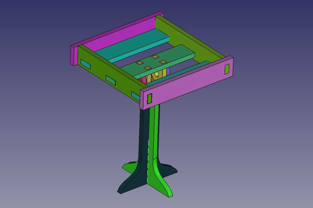
Unfortunately during my modeling I had not taken into account the dog-bones for the joints of my model. I had redone the modeling of the support in a parametric way and this time with the dog-bones for the joints.
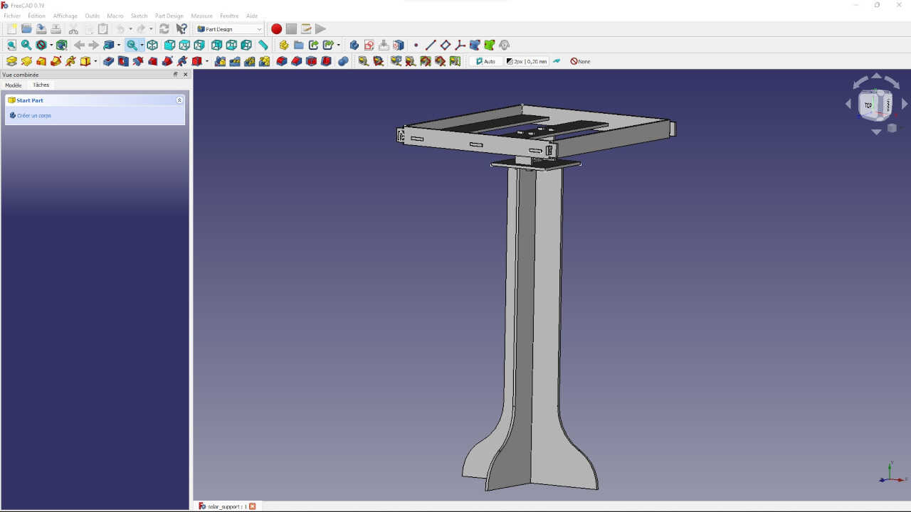
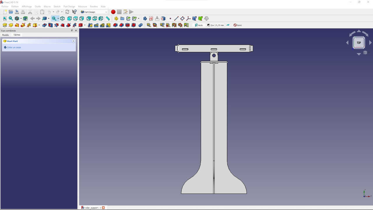
1. Parametric design of the part using FreeCad
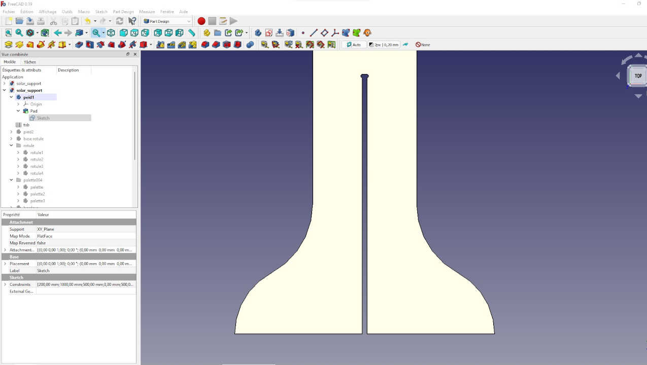
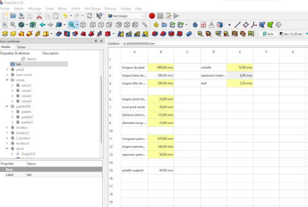
I present below my model:
Note, it is extremely important to parameterize your design so that you can change variables such as the material thickness based on the test fits as shown below. The photo below shows the FreeCad spreadsheet that was created for this assembly.
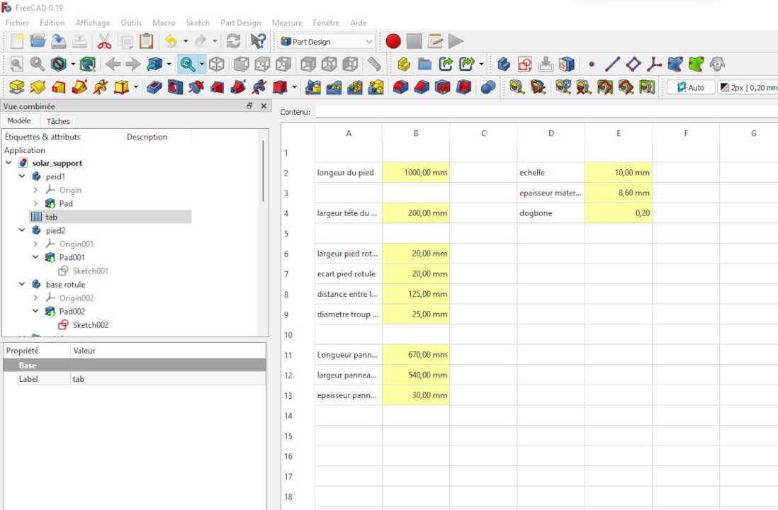
Note that the types of joints used for this design are as follows: - Press-fit joint - Wedge joint The types of cut used for each joint was the t-bone cut and dog-bone. Photos of the final joints will be shown below.
2. Tool path
For the preparation of the tool path, the process used is the same as the one used for the creation of the tool path of the test fit on Freecad. Therefore, for the creation of the tool path of the different parts of the solar stand, we can refer to the process used for the creation of the test joint.
Note that the test piece results resulted in a material thickness required of 8.8 mm.
For this we will review the FreeCad setup file we created and update the spreadsheet to reflect the results of your fit test. In my case, I had to change the thickness to 8.8 mm, as shown below.
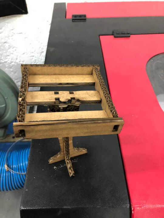
3. work on the cnc
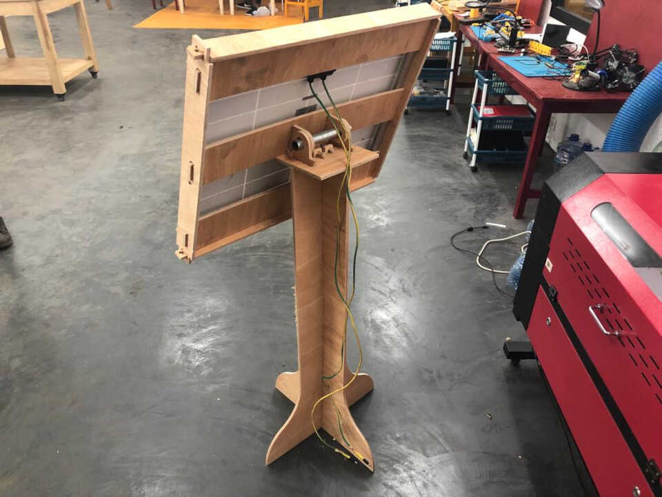
At this stage we follow the same path made during the group work, which allows us to have this final result:
File
- 3D fil:
- Pressfit
- Solar support
- NC file for cnc
- Pressfit
- Solar support
## Wrapping up
In conclusion, everything went well overall. Considering the size and cost of this machine, we tried to take every precaution to avoid any damage 😅. This was my first time working on such a large machine, so it was another week full of new knowledge.