4. Computer controlled cutting
Group Assigment
We were tasked to chracterize our Lab’s lasercutter’s focus, power, speed, rate, kerf and joint clearances.
Lasercutter machine
OMTech Upgraded 100W CO2 Laser Engraver Cutter 20” x 28” Laser Engraving Machine
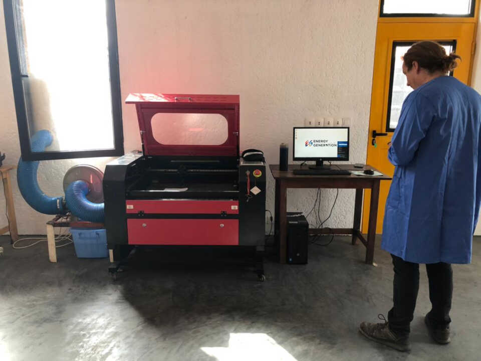
image: this is our Lab’s lasercutter
| PRODUCT | SPECIFICATIONS |
|---|---|
| Power | 60W |
| Software | Ruida DSP Control System |
| Engraving Speed | 0-23.62 in/s |
| Engraving/Cutting Thickness | 0-0.39”(depending on materials) |
| Data Transfer Interface | Flash Drive; USB to PC; Ethernet to PC & Offline Capabilities |
| Working Size | 20” X 28” |
| Compatible System | Windows, MacOS if you use LightBurn software (not included) |
| Cutting Speed | 0-15.75 in/s |
| Lift Table | 0-9.1” |
| Supported Graphics Formats | HPGL; BMP; GIF; JPG; JPEG; DXF; DST; AI |
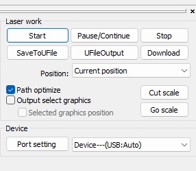
Lasercutter Sofware
The software used to drive the laser cutter is RDWORK V8. You can download it at this link
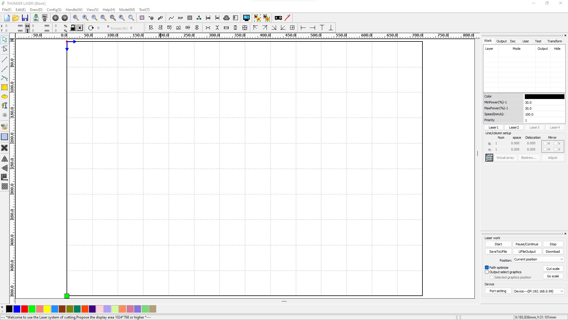
The software communicates with the machine via a USB cable.
After making a design on the software, we first check that the right port is selected and then to start the cutting process, we just click on the start button.
Focus
We started by calibrating the focus of the machine. We leveled the bed from bottom to top until we reached our bare level. We did some laser drilling tests to observe the different cases of focus until we had the perfect height
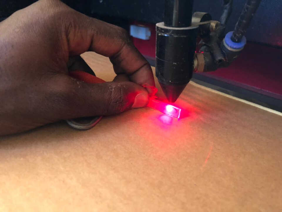
image: using the focus kit that came with the machine
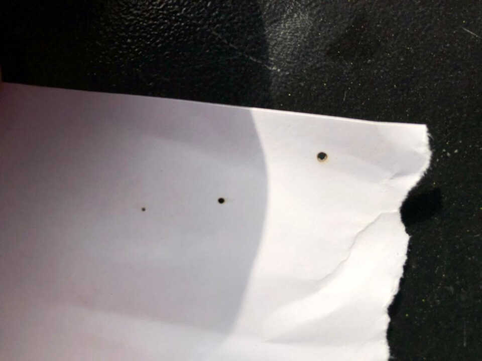
image: here you can see the various laser drill test holes at various heights
Power, Speed
At this stage we worked on the power and speed parameters to observe different rendering.
Mode scan

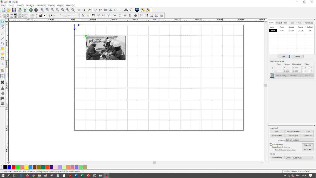
After having made on a cardboard 4 tests with different parameters here is the result obtained.
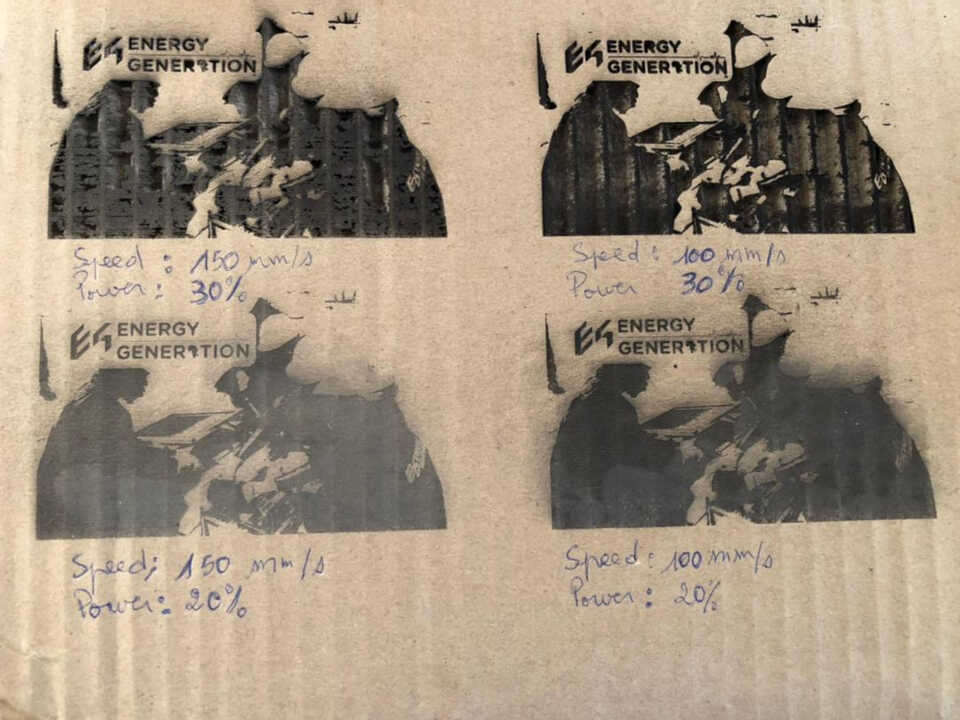
We can notice that the parameters that did not burn the cardboard are the two images that had as power 20% with a speed of 150mm/s for one and 100mm/s for the other
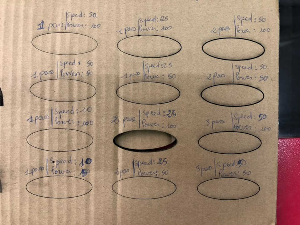
Mode cut
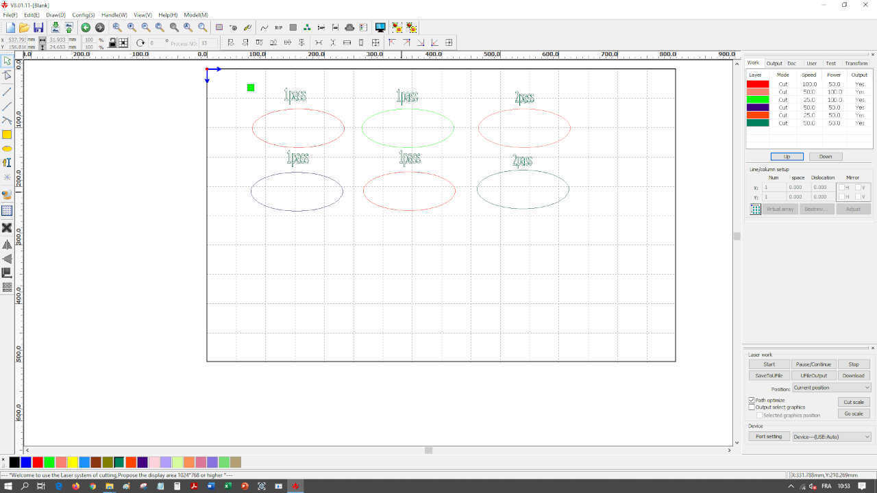
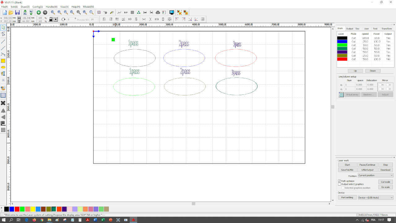
For cutting, we have several to get the ideal setting. On the picture below you can see that the right setting was 25mm/s for speed and 100% for power
Kerf and joint clearance
- Joint clearance
We create a test piece in cardboard and plexiglass with different kerf dimensions allowing us to observe the ideal kerf. The cardboard has a thickness of 6.3mm and the plexiglass has a thickness of 3.8mm.
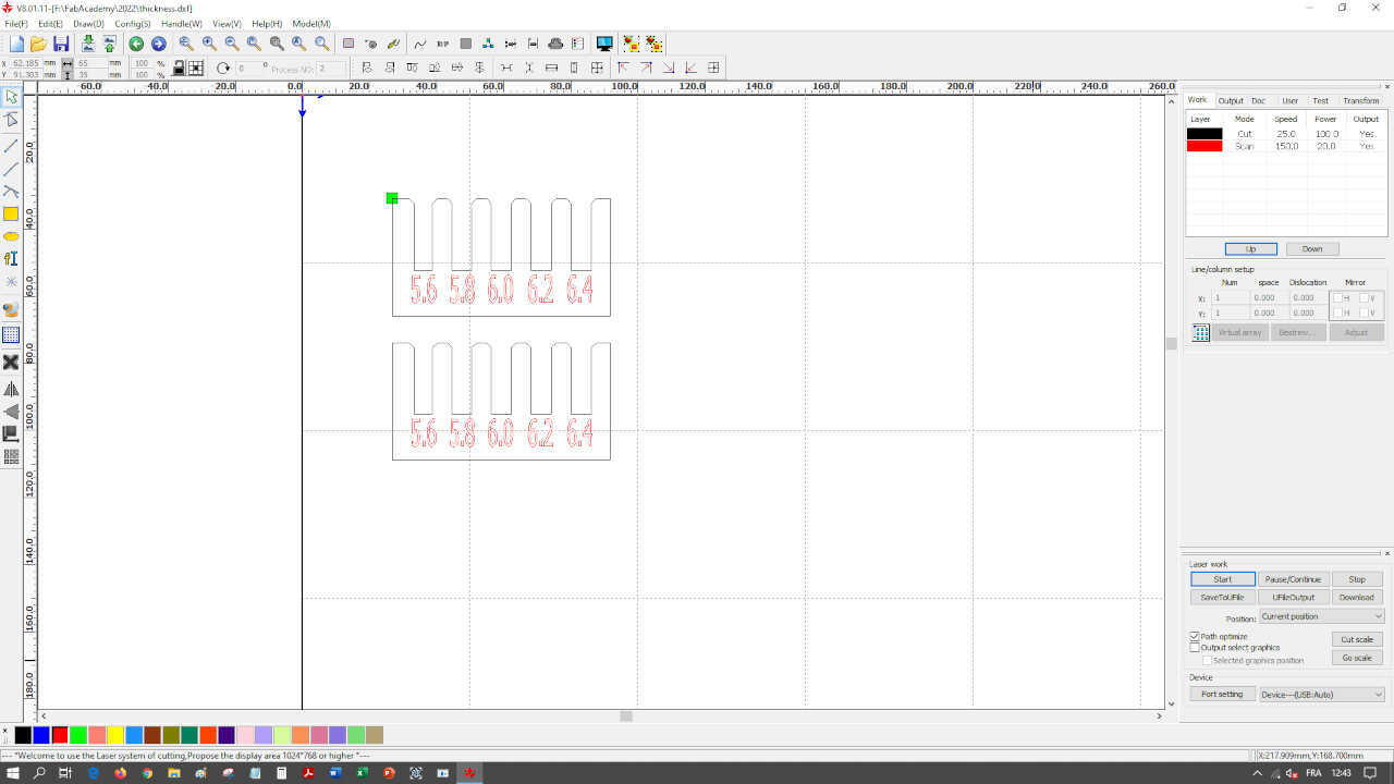
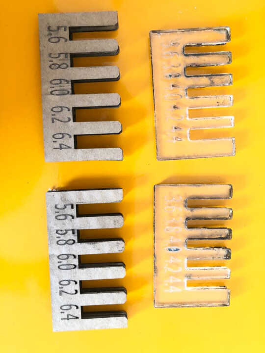
We have observed that for cardboard, the joints get stuck more with the 5.8mm dimension and for plexiglass the joints get stuck with the 3.6mm dimension
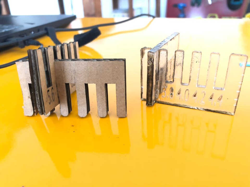
- Finding the kerf
Because the kerf is a dimension smaller than a millimeter, measuring it can be tricky. A good strategy is to cut six 10 mm strips in the CAD software (which means 7 cuts), cut them, place them next to each other and measure the total length. The kerf is then calculated as (planned length - measured length) / number of cuts.
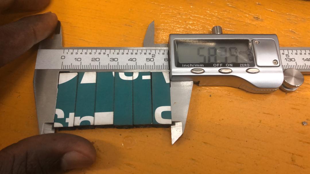
For this laser cutter it is (60.0 - 58.39) / 7 = 0.23 mm. This number will be used in all other designs.
Personal Assigment
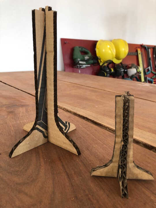
Designing and lasercutting a parametric press-fit construction kit
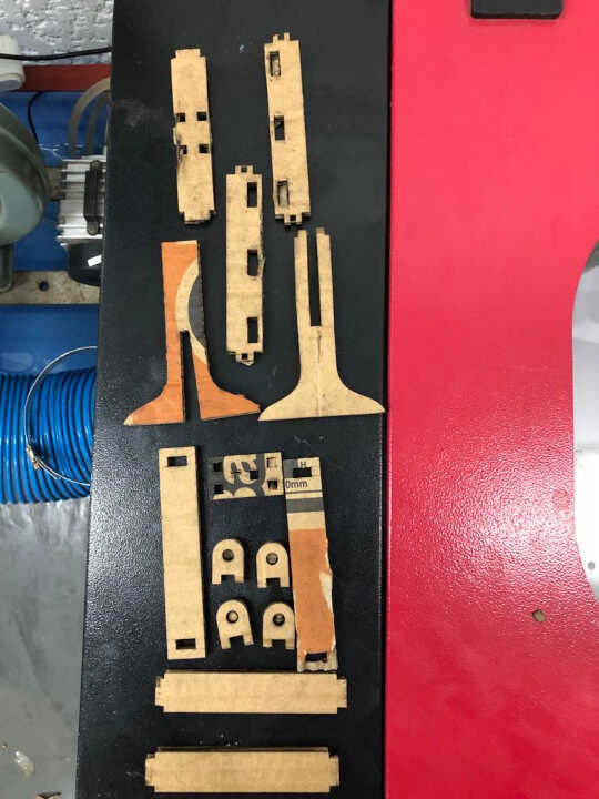
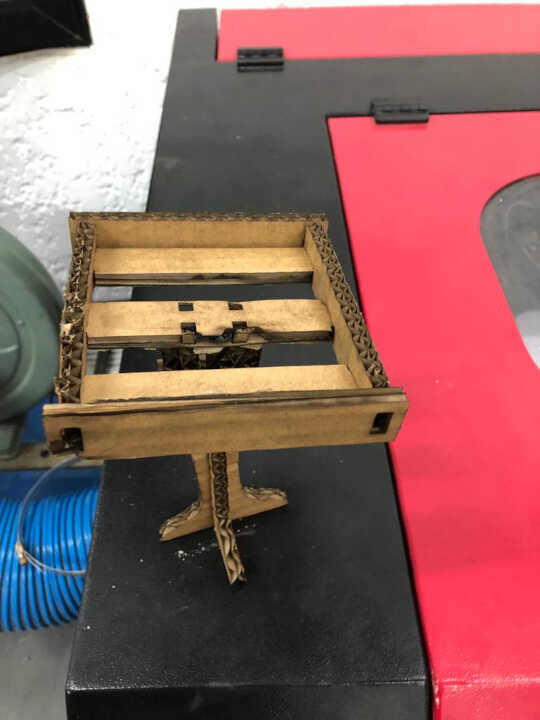
For my final project, I need a bracket for a solar panel that will power my system independently. So I have modeled the support in several attachments that I will then assemble.
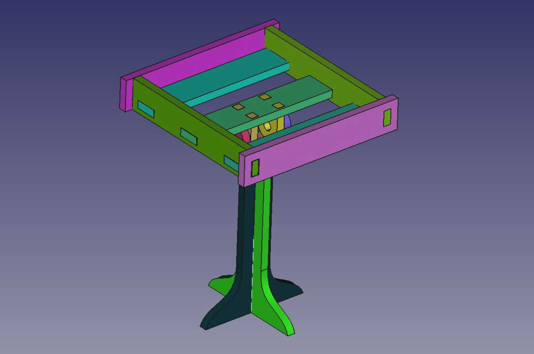
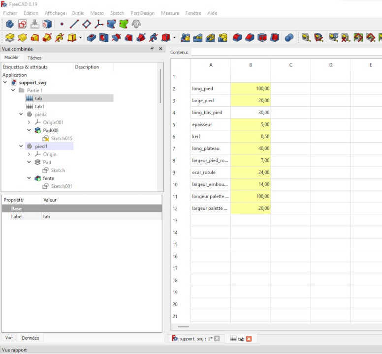
During the modeling of the support I used the spreadsheet workshop allowing me to parameterize in a relational way all the parts of the support. This will allow me to make a first reduced model before making a larger model by simply modifying the values of the spreadsheet.
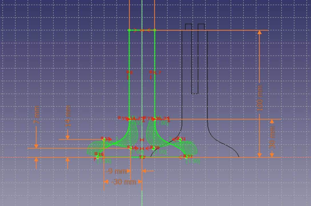
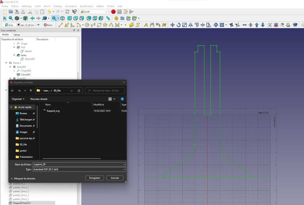
After finishing the modeling of the different parts, I created the 2D model of each part with the Draft workshop
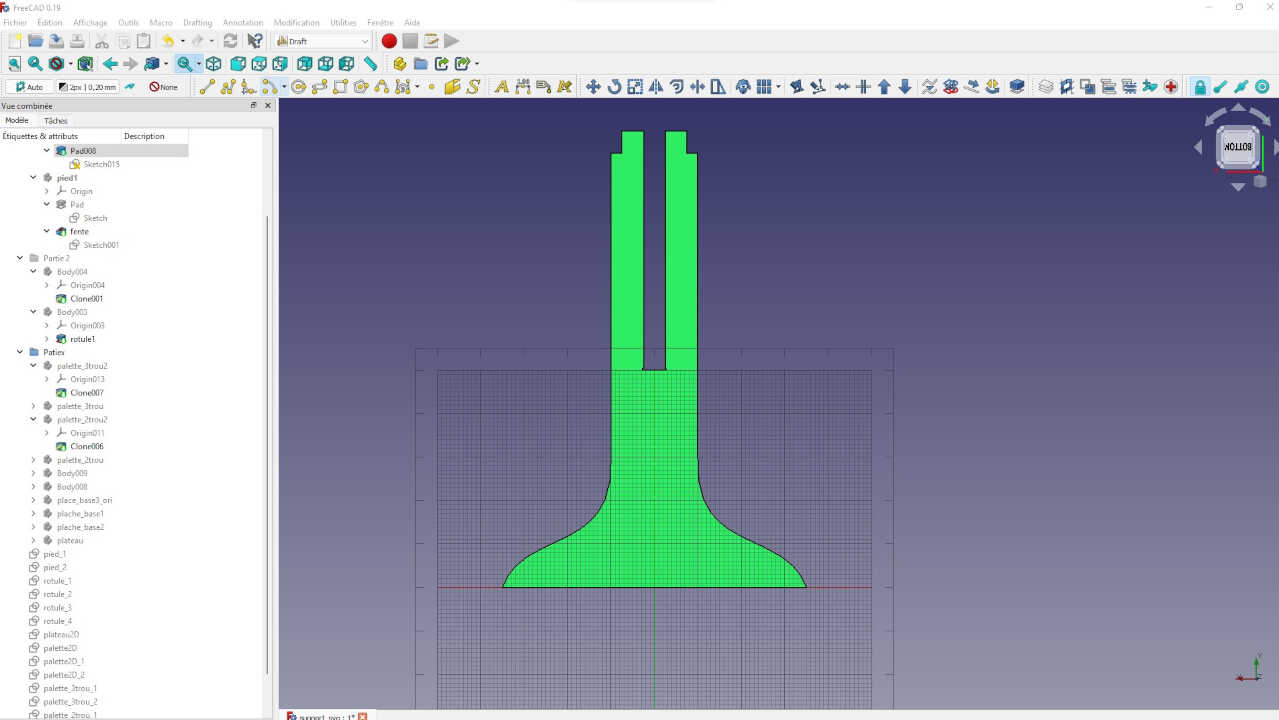
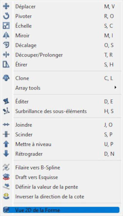
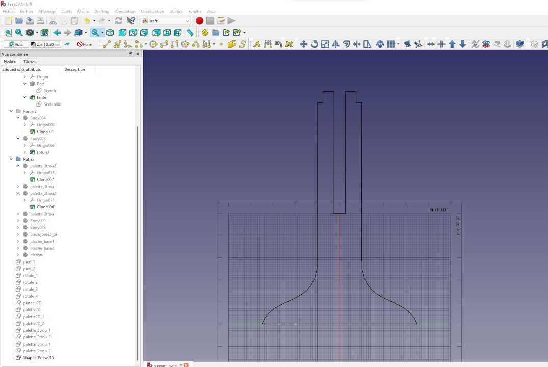
After making the 2D view of all the 3D models, I exported the 2D view as a dxf file before sending it to the laser cutter
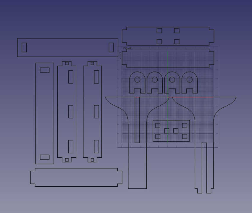
By doubling the value of my parameters, I automatically get a shape twice as big.
Vinyl Cutting
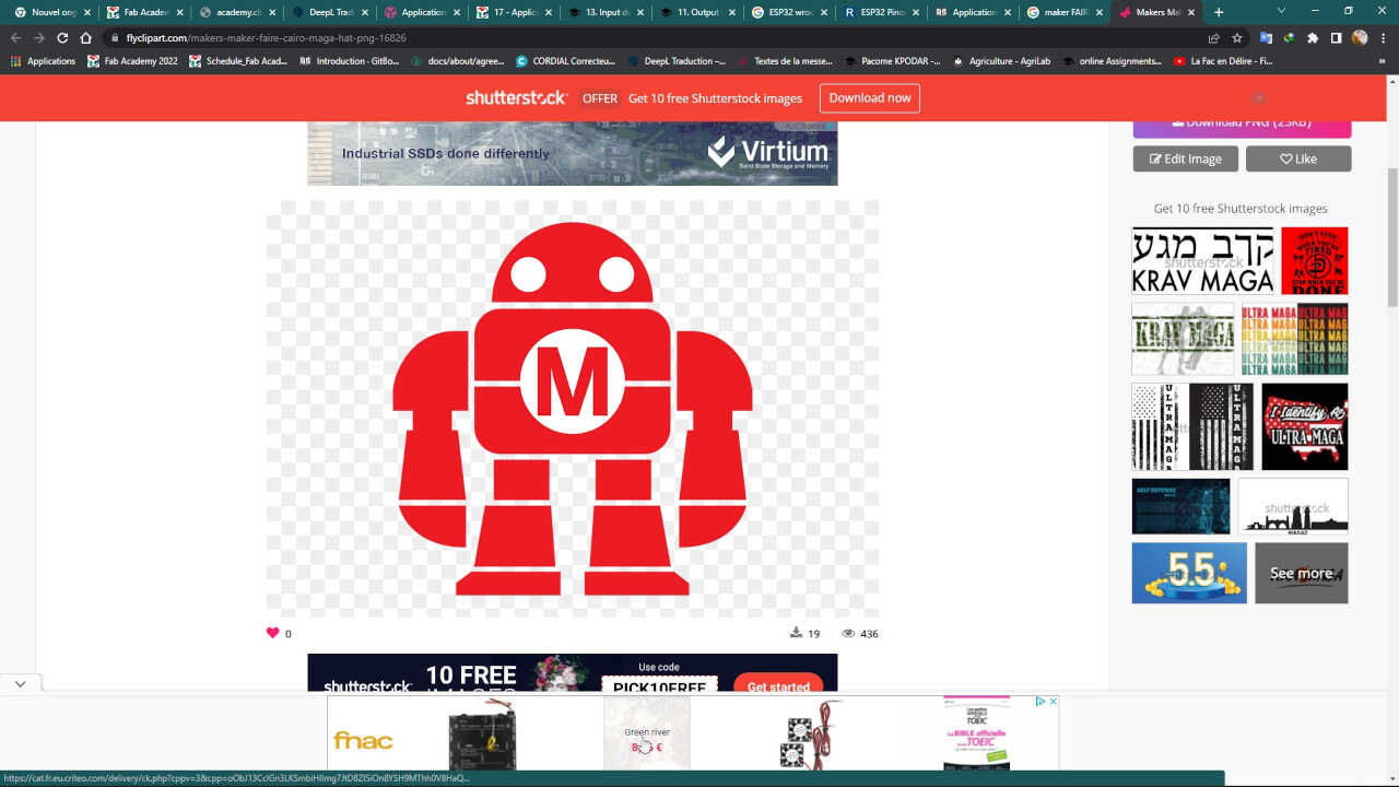
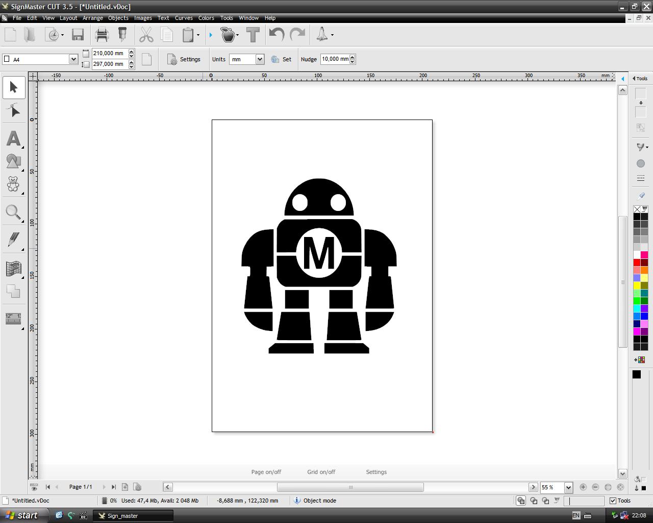
For this assignment we will use the image below which corrects the same image used in the previous assignment (week3 Computer Aided design)
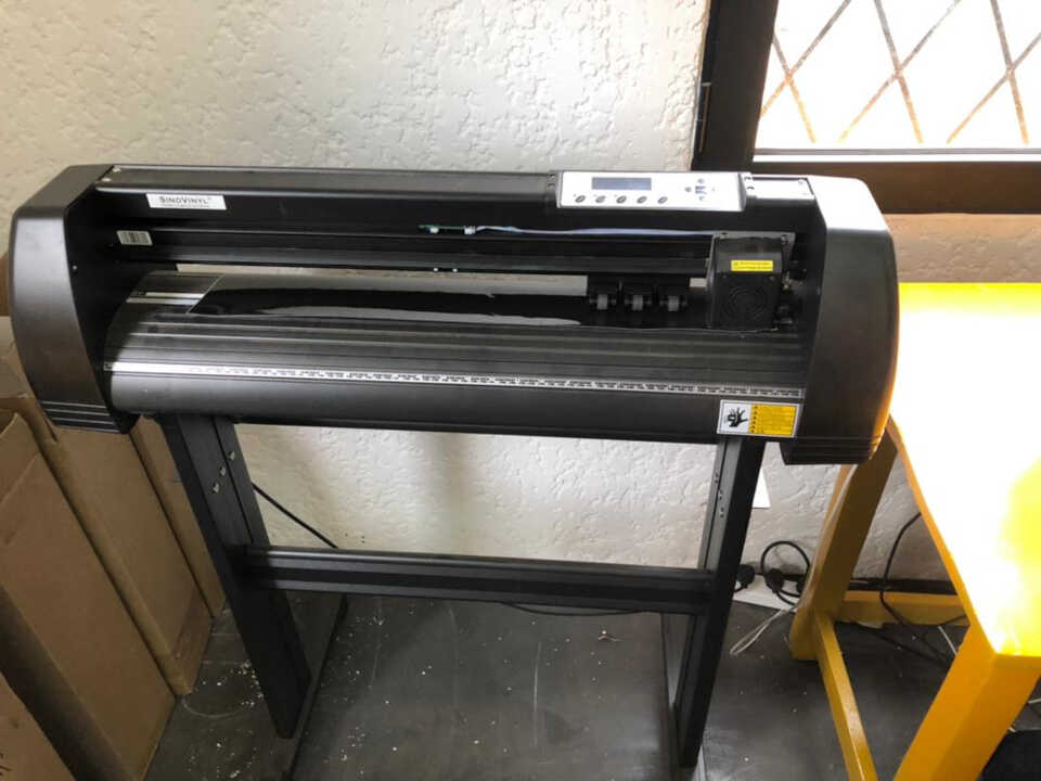
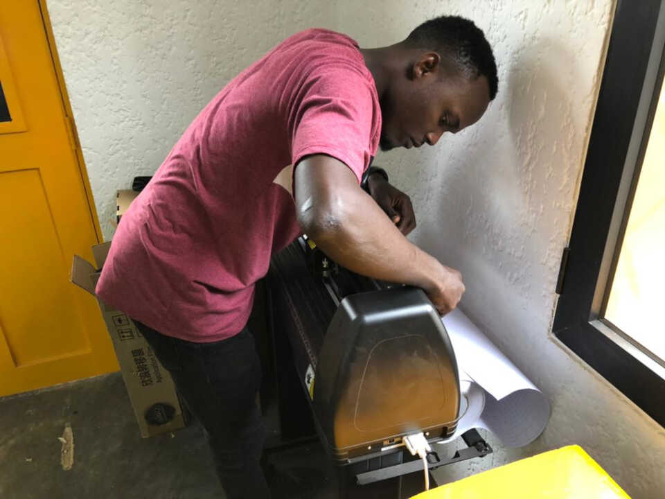
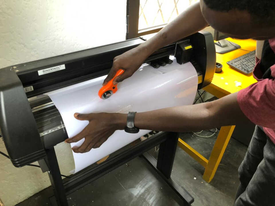
The cutting was performed using a SINOVINYL 1351LA as pictured below:
| Machine | Specifications |
|---|---|
| Cache Capacity: | 1MB-4M |
| Paper Feed Width: | 1350mm |
| Cutter Pressure: | 0-800g( digital adjustment) |
| Cutting Width: | 1260mm |
| Cutting Speed: | 400mm/s |
| Driver: | High stepping motor, micro-step driver |
| Cutting Length: | Max 20000mm<=20 |
| Repeat Cutting: | Yes |
| Size: | 1351mm |
| Input voltage: | 110v/220v |
| Control panel: | over-head, 2*8LCD, 13-botton touch thin-film keyboard |
| Packing: | Hard carton |
| Operation system: | Windows XP,Vista,Windows7 |
| Max cutting speed: | 400mm/s |
| Knife press: | 0-800g( digital adjustment) |
| Application: | Vinyl and paper graphic cutting |
| Main board: | 16-bit CPU, 1MB-4M High-speed CACHE memory |
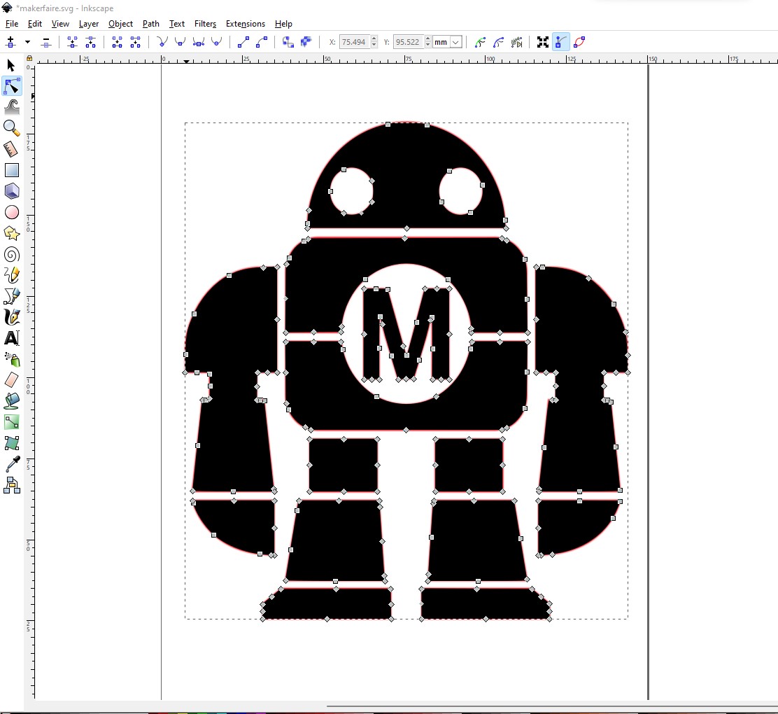
To begin I create the svg file of the image to use. You can refer to the previous assignment to see how I create an svg file from the same image.
Now we go to the vinyl cutter to install the vinyl to be used.
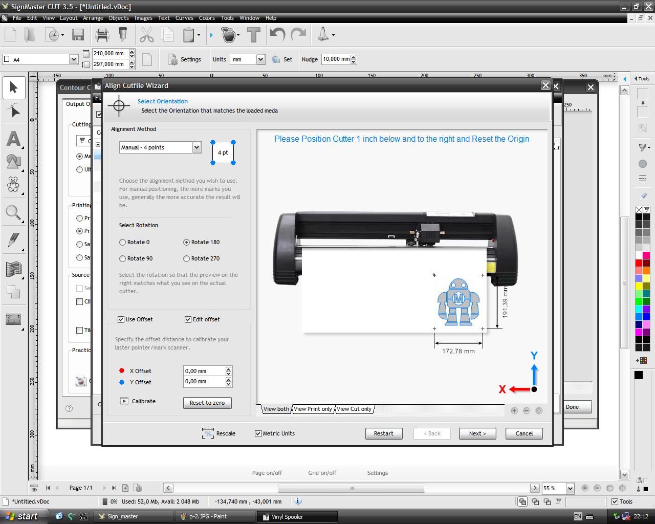
The software used for the vynil cutter is SignMaster CUT 3.5
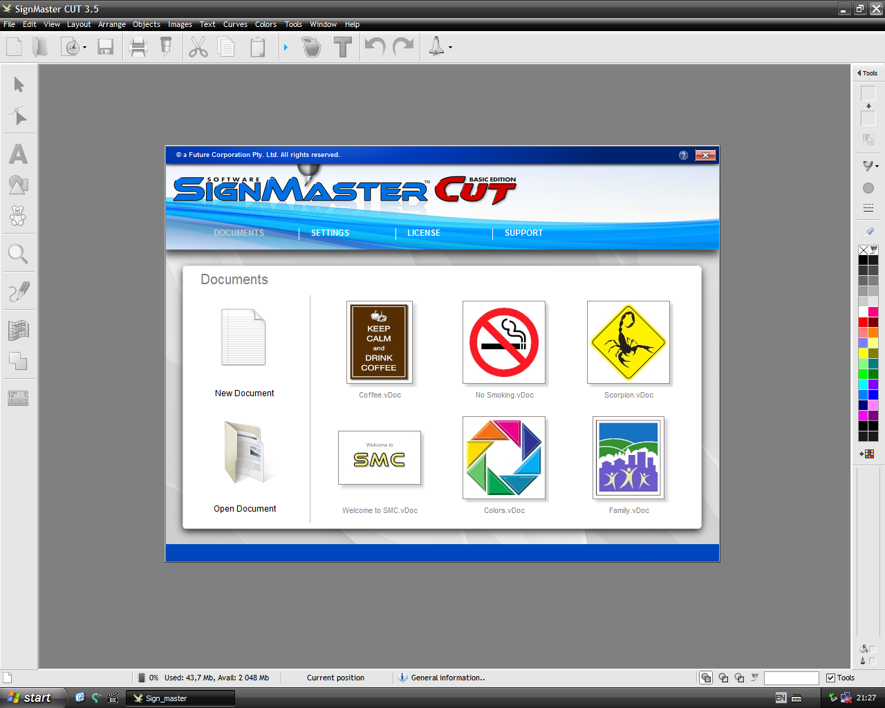
we open inside the svg file generated on inkscape
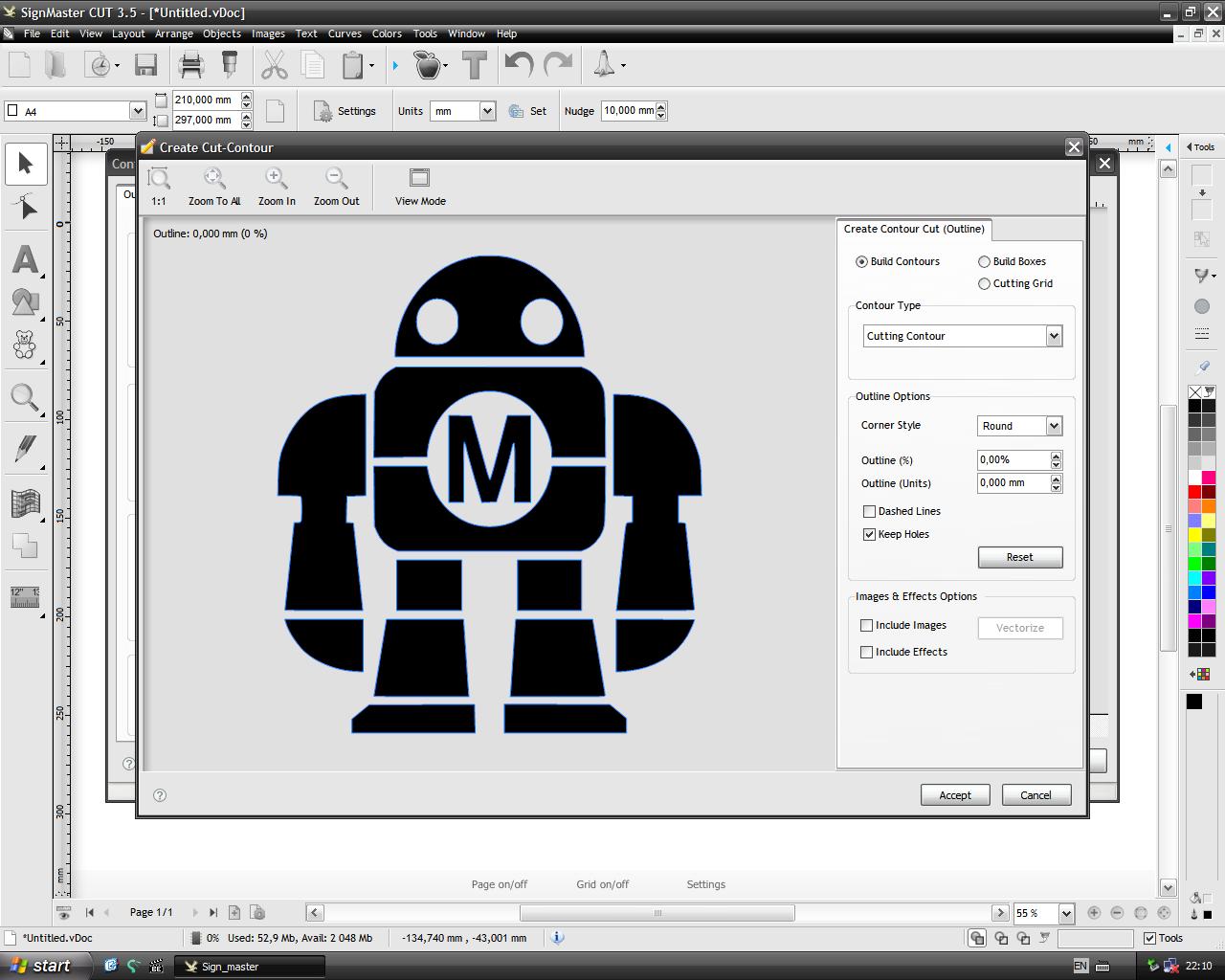
To launch the cutting it is necessary to go to the tab file>Contour Cutting>Contour Cut wizard.
In this window just click on the Accept button.
Click on the Next button to validate the default orientation and start cutting the vinyl.
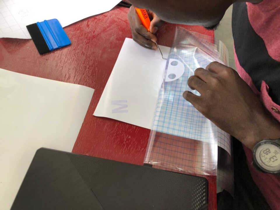
After cutting the vinyl, I remove the part on which the cutting was done.
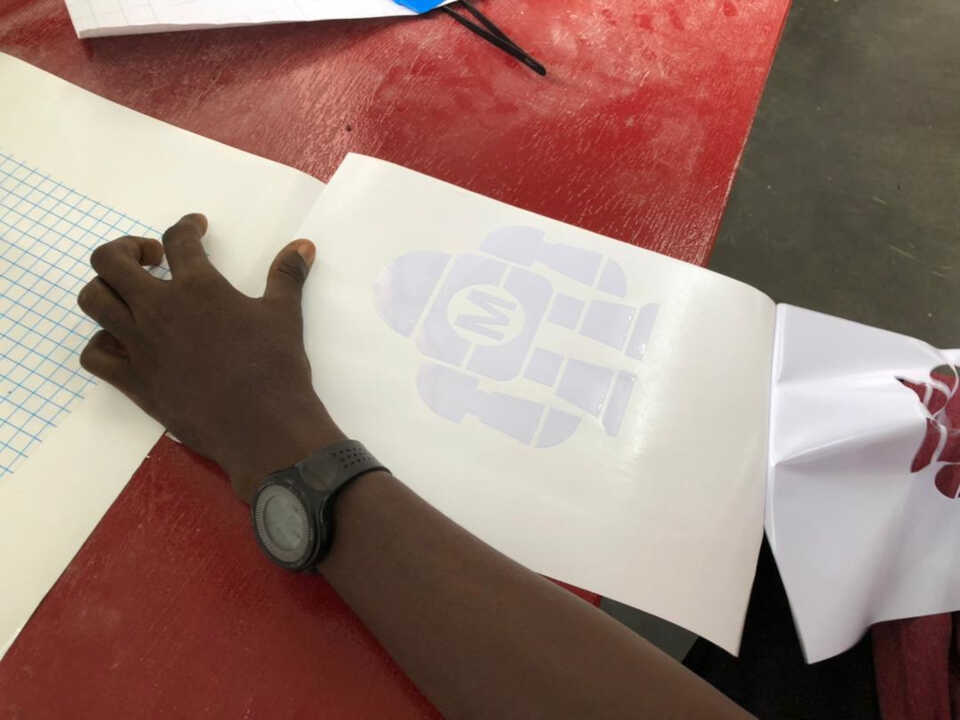
then I remove on my sheet, the unitile vinyl to leave only my image.
I place a transfer sheet on my vinyl sheet, then remove the design and glue it to the computer.
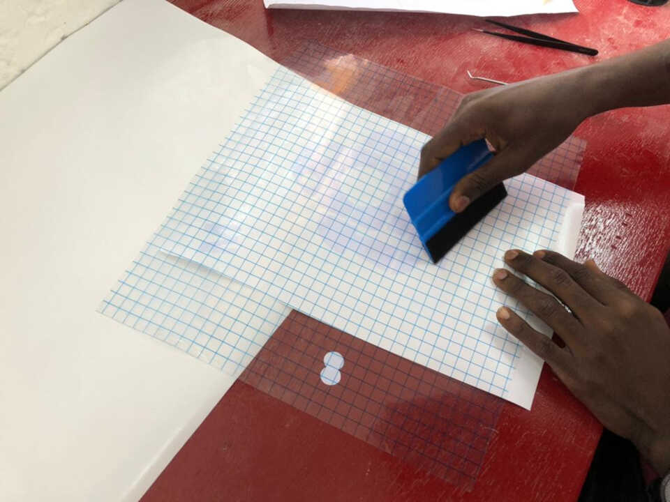
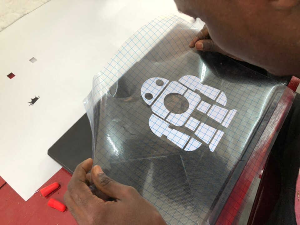
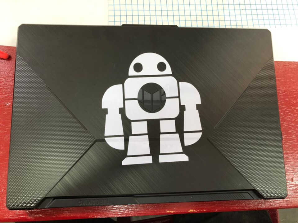
After cutting I used the transfer tape to transfer the logos onto my laptop yielding the final result below.
Files
image scanned by the laser cutter
What went wrong/What went wel
Overall, everything went well. I had used a laser cutter before, but only to do image engraving. With this job, I got to know the laser cutter better. The vinyl cutter was my first time and now I’m looking forward to making more steakers to better beautify my computer.
However, the only thing that was wrong was the cardboard used for the laser cutter. The problem was that the cardboard used was not a uniform thickness and this affected the fit of the joints.