3. Computer Aided design
This week’s assignment is to model a possible final project, compress our images and videos and post them on our class pages.
Part of the 2D
Raster vs Vector
To design a 2D image, it is important to know that we have two types of image format:
- The raster format (jpg, gif, png…)
- The vector format (ai, eps, svg…)
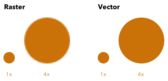
The main difference between these two formats is that a vector image can be enlarged without losing its quality, whereas a raster image loses its sharpness when enlarged.
The raster image (or bitmap): It is composed of small points called “pixels” that we do not see with the naked eye. When a raster image is enlarged, this image is no longer visible to the naked eye. When a raster image is enlarged, it becomes blurred because the pixels come out, these are the squares that appear on the screen.
The vector image: It is composed of lines of segments that are linked together by mathematical formulas. It is a system of proportionality and coordinates. Thanks to vectorization, each element has a well-defined place which prevents the image from being distorted.
Inkscape
For the learning of the 2D, this week I worked on the software inkscape.

Inkscape is a professional-quality vector drawing program that runs on Windows, Mac OS X and GNU/Linux. Inkscape is used by professional designers and hobbyists worldwide to create a wide variety of graphics such as illustrations, icons, logos, diagrams, boards and web renderings. Inkscape uses the W3C open standard: SVG (Scalable Vector Graphic) as its native format, and is free and open source software.
You can download the software at this link
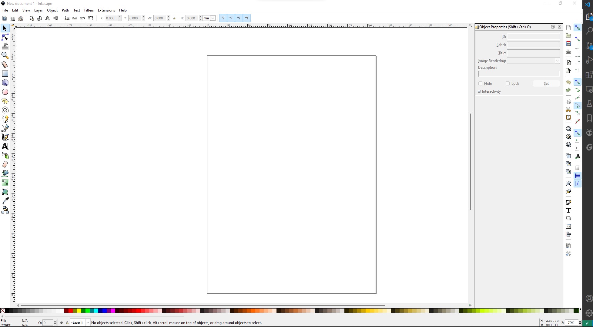
After installing and opening the software, it looks like this.
I was looking for an idea of what I could do on Inkscape and my instructor gave me the idea to create an svg file to be used in the next assignment by the vinyl cutter to make a steaker for my laptop.
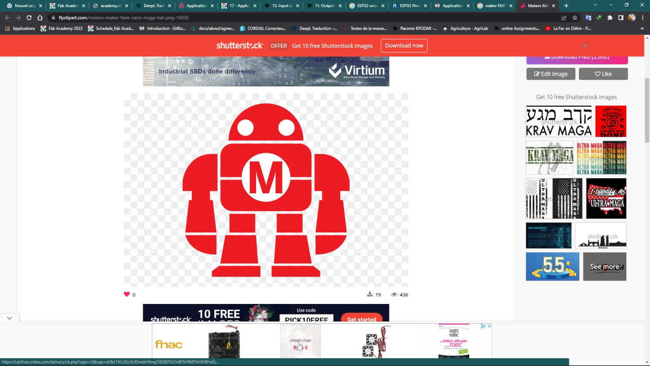
So I downloaded the png logo of makerfaire on a site.
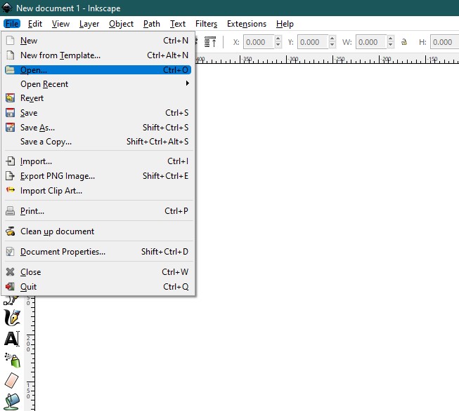
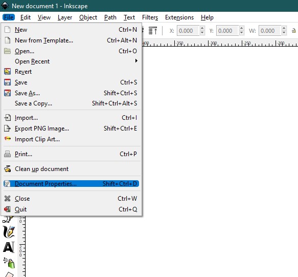
After downloading the logo, we open it in Inkscape by going to the File>Open tab.
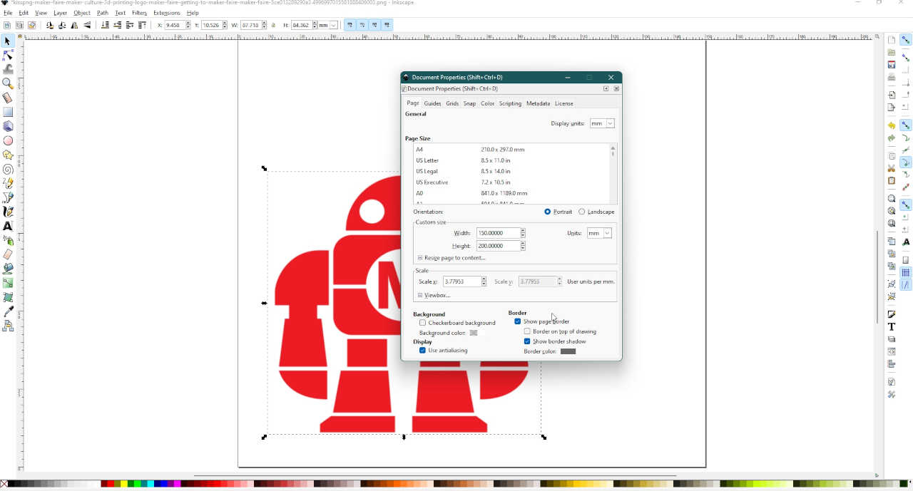
As the image is to be pasted on my computer, it is important to resize it. To do this we click on the tab file>Document Properties
I took 200mm as height and 150mm for the width
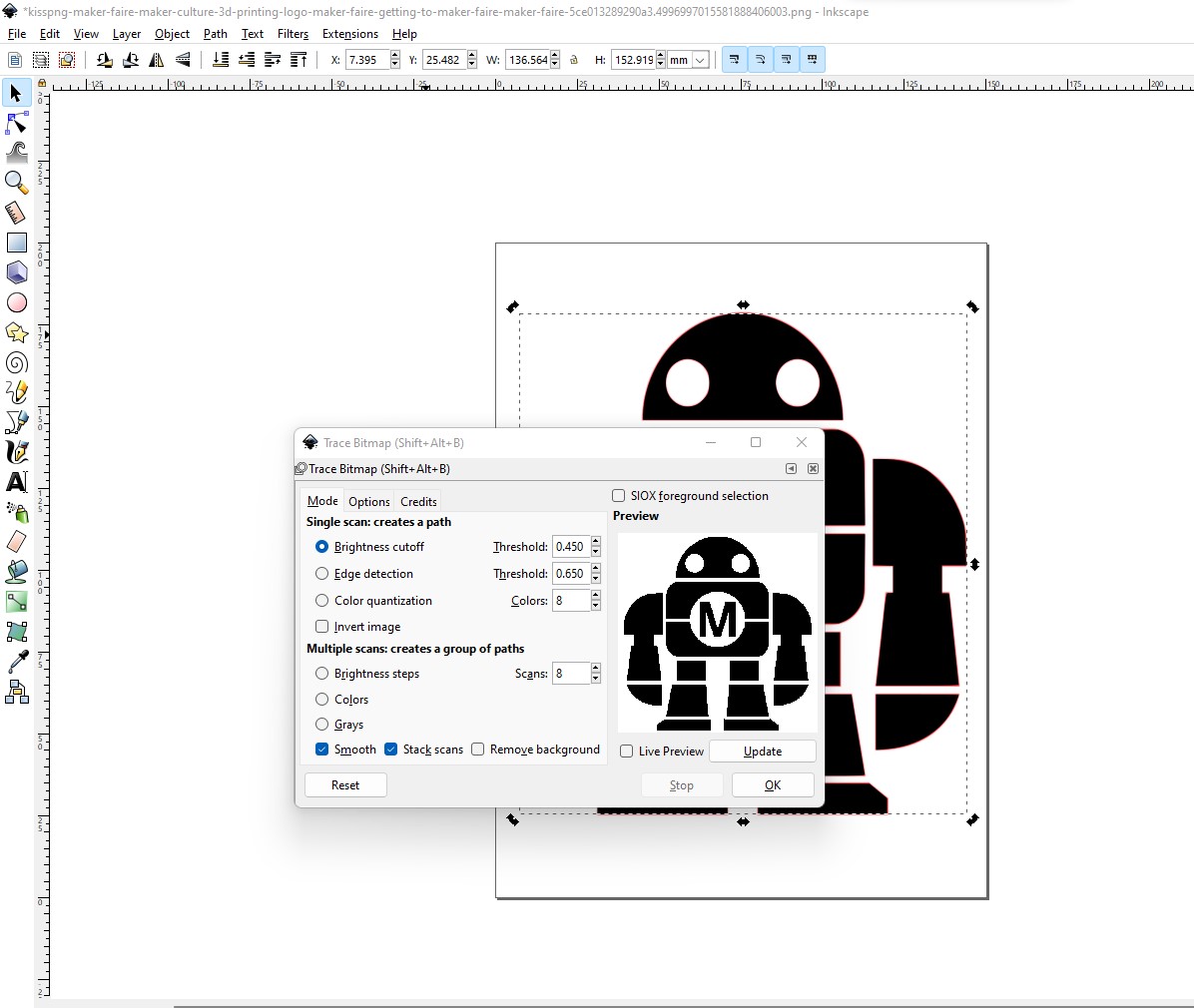
For the next step, we create a trace bitmap, which will allow us to transform the image into several editable shapes. To do this, we click on the Path>Trace bitmap tab and validate in the window that opens.
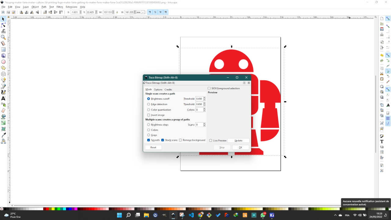
When you click the OK button, a second image in black is created above the initial image.
By double clicking on the image is black, we can see the different shapes that make up the image. From this step, I can save this image as an svg file but I will go further to show how I can modify this shape to my liking.
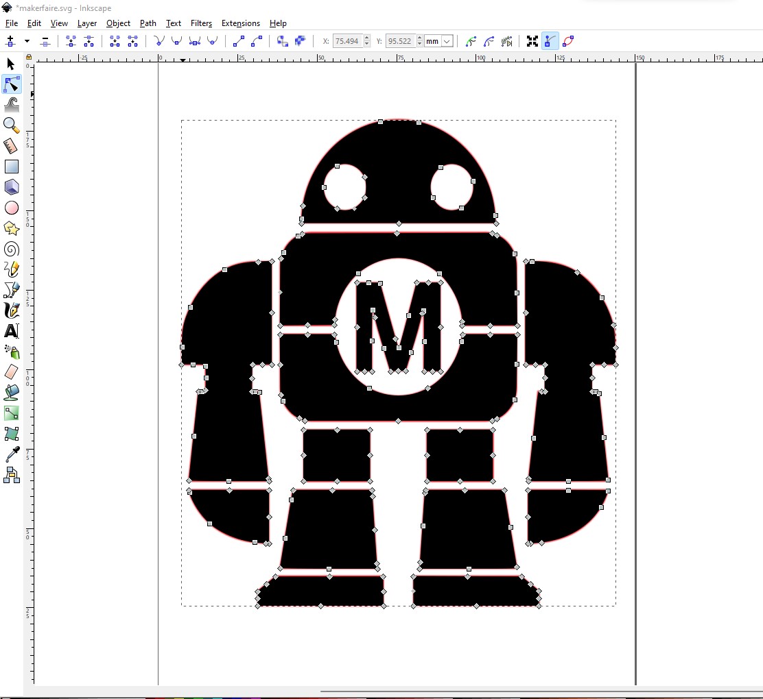
To change the shapes, you just have to move the little squares. By moving some of these squares, here is the result I get below.
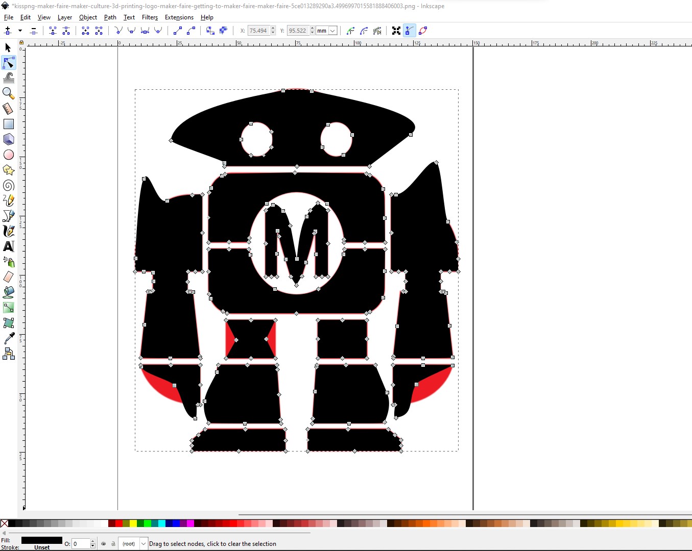
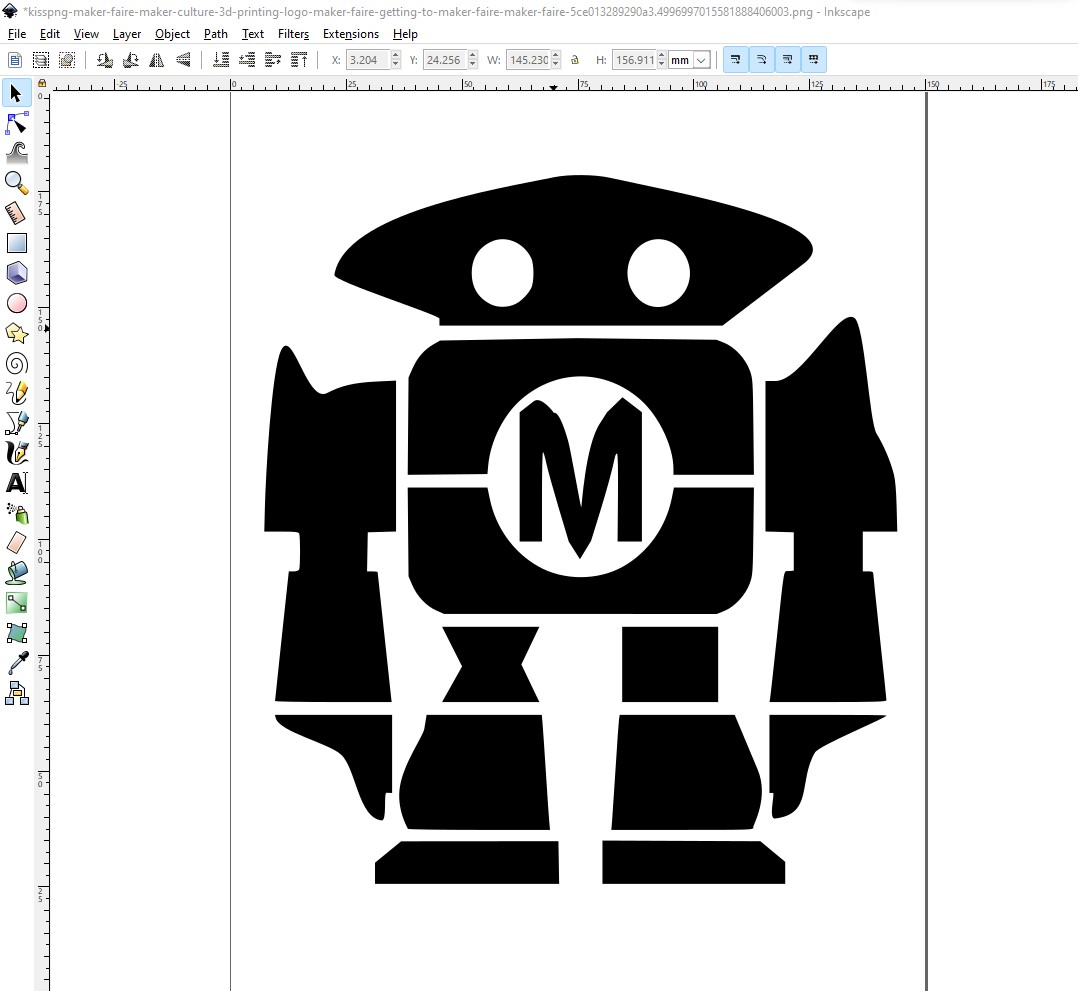
We can see that the original shape was underneath. We can delete it by clicking on the red part and then pressing the delete button.
To save the result in svg we go to File>Save as… and there in the window that will open we choose the extension svg
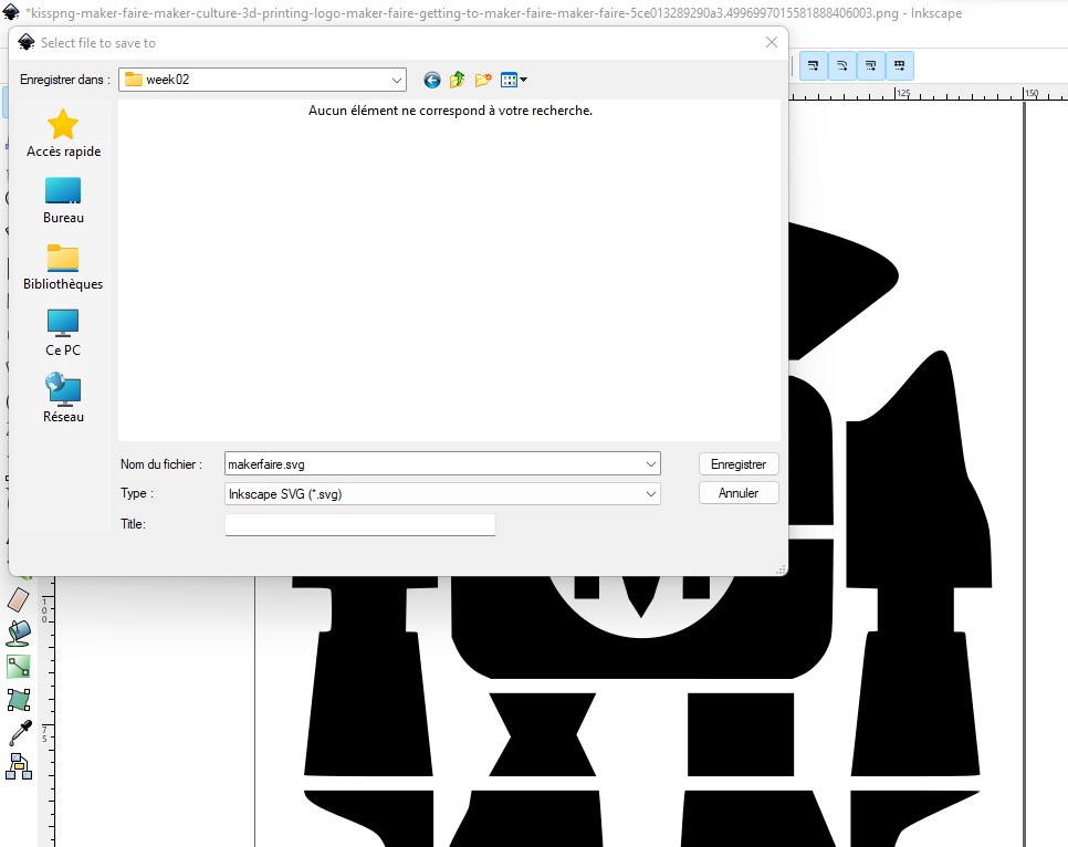
Image compression
In the documentation of each week’s assignments, we use images to better explain our work. However, it is important to compress these images to reduce the size of these files before pushing them to gitlab.
To do this I use the gimp software (which is an open source graphic editor that you can download at this link) to which I add a BIMP plugin, downloadable at this link.
After installing gimp in addition to its bimp plugin, we open gimp and go to the file tab and click on the Batch Image Manipulation Plugin sub-tab.
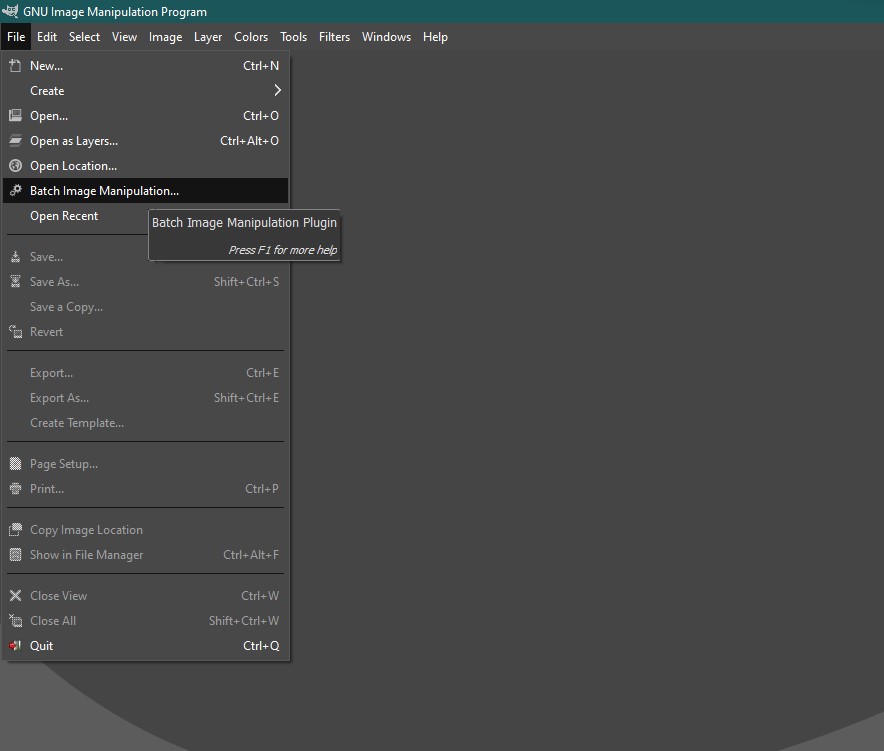
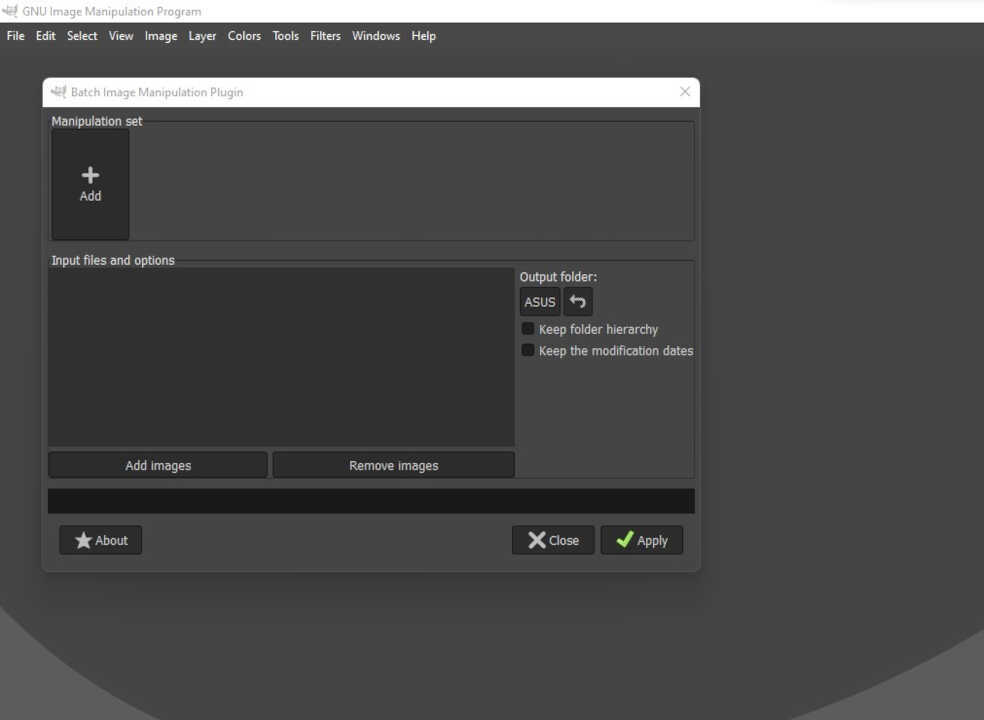
After clicking, the bimp window opens as shown in the image below. So, to compress an image, we first select the image to be compressed by clicking on the Add images button. Then we choose the folder in which the compressed image will be saved at the end of the process by clicking on the Output folder button.
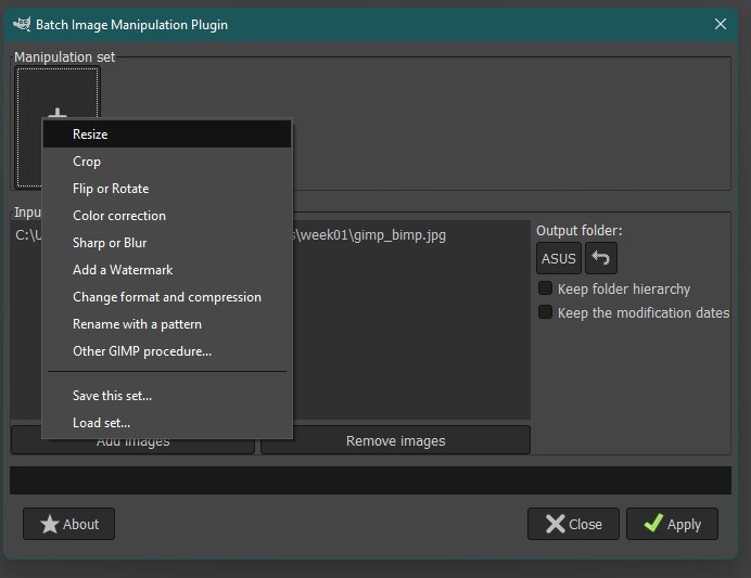
Now we click on the +Add button located in the Manipulation set part.
There are several tabs, but the ones we are interested in are Resize and Change format and compression .
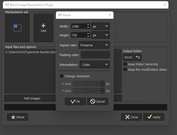
These are the settings used for Resize.
Here are the format change and compression parameters.
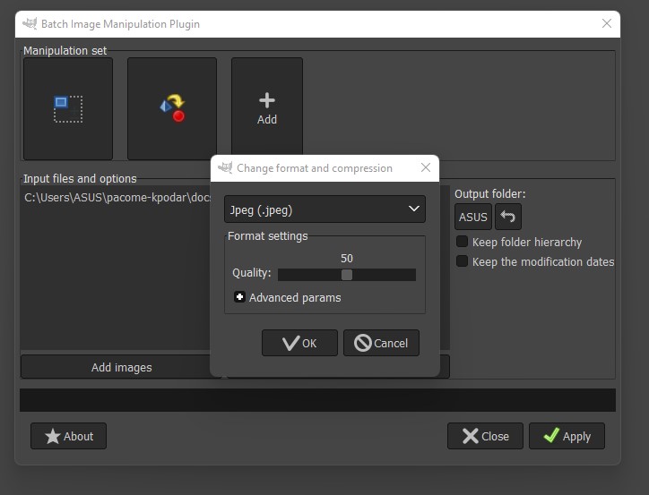
After the settings we press the Apply button and the chosen image will be compressed.
Below I show you an image that weighs 50Kb.
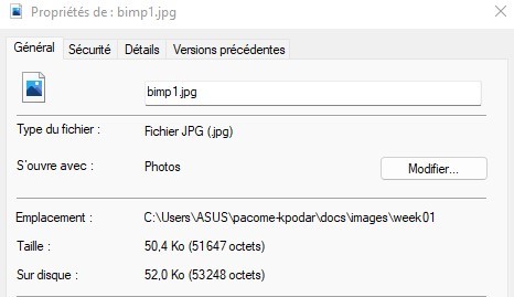
After compression, the image weighs 32Kb

Part of the 3D Modeling

My work on Freecad will consist of modeling a valve motorization system. For this fact my modeling will include several parts. I will proceed to model part by part before assembling the whole.
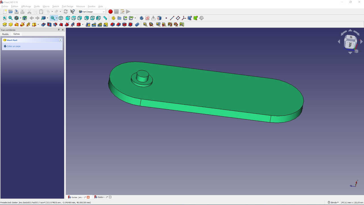
To begin I model the box which will contain my motor with all the embedded electronics. This box will be clamped to the valve, so it will need a kind of foot.
To make the box I must first make a sketch of the box with all the constraints that the sketch must have.
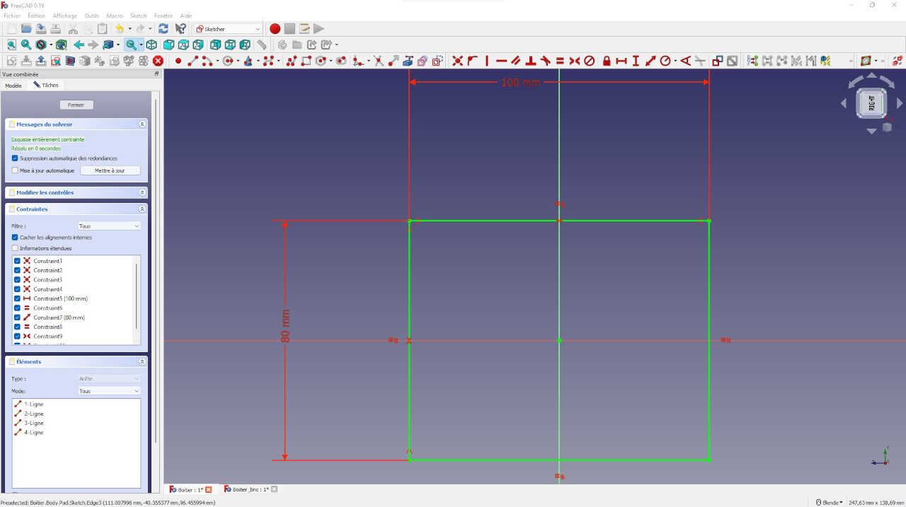
After making my sketch, I make a 60 mm protrusion of my 2D plan
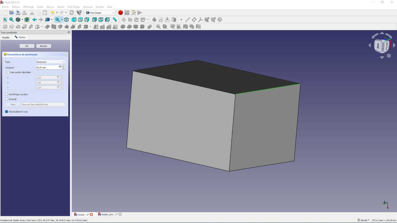
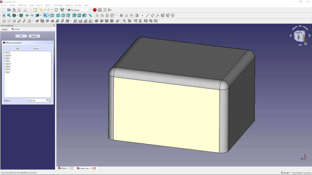
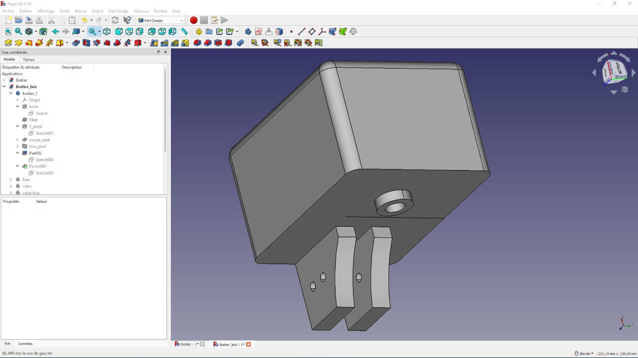
We now have a rectangular parallelepiped. To make it a bit nicer I’ll apply filleting on the edges except the stops of the base of the box.
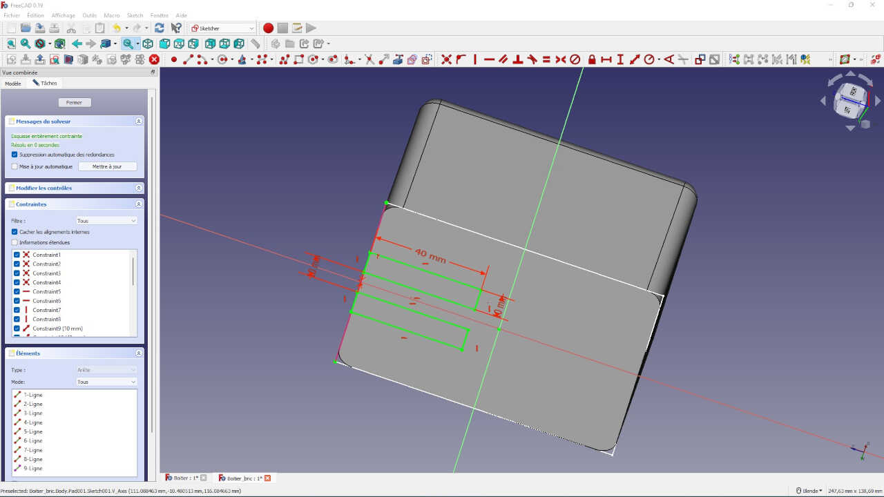
I said above that the box will be placed on a valve, so I need a kind of foot for my box. For that, I select the base of the box where the feet will be and I draw my sketch on it before I can make its protrusion
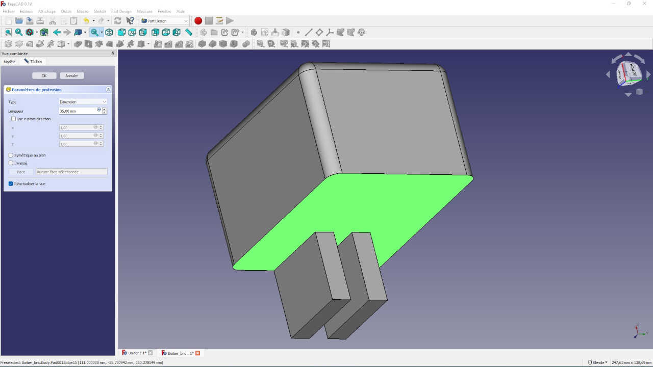
We now have our box with two legs but I’m going to try to make a cut at the legs to make them look a little nicer 😊.
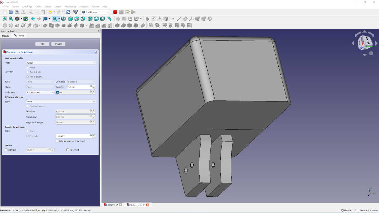
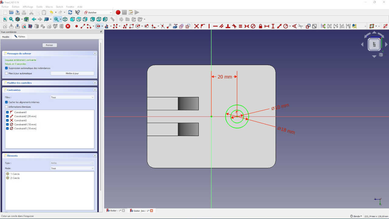
I took the opportunity to add two holes at the feet that will be used for a screw. I did this by selecting the outer wide side of a foot on which I sketched the two holes and then I made a drilling. In the drilling parameter, for the depth I selected “Through all”, which allows me to have a drilling on both feet without worrying about the depth of the hole
the box is almost finished, I just have to add the part where the motor shaft inside the box will turn. so I quickly make my sketch and prototype my 2D shape in 3D with a cavity inside.
the first part of the modeling is finished we will move to the second part by creating a new body. we can hide the first body by selecting it in the combined view of freecad and pressing space.
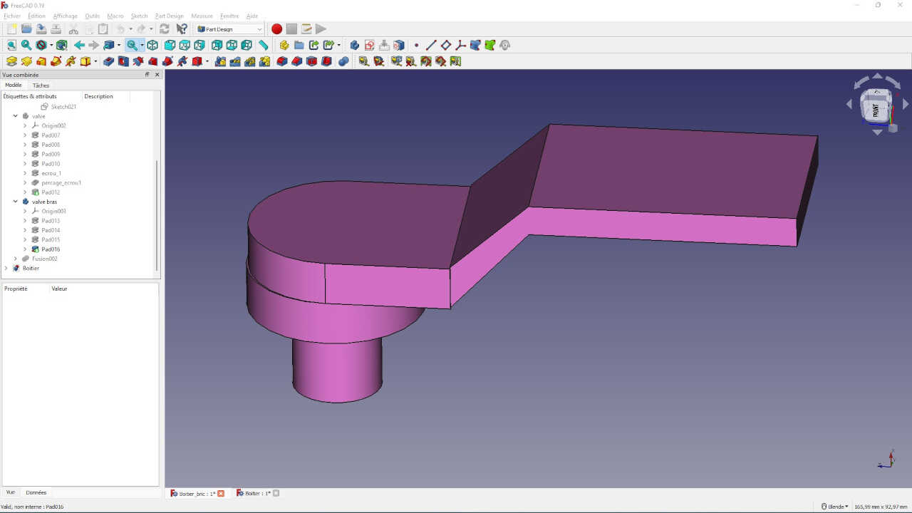
The second body will be the arm that will drive the opening and closing of the valve arm. It will then be connected to the box at the output of the motor shaft.
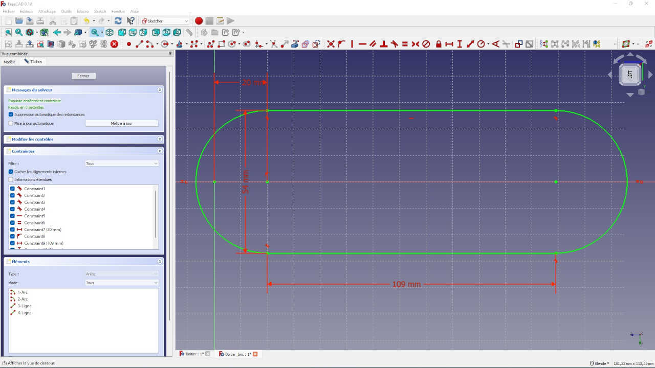
So to start I create a sketch of the arm that I will then protrude
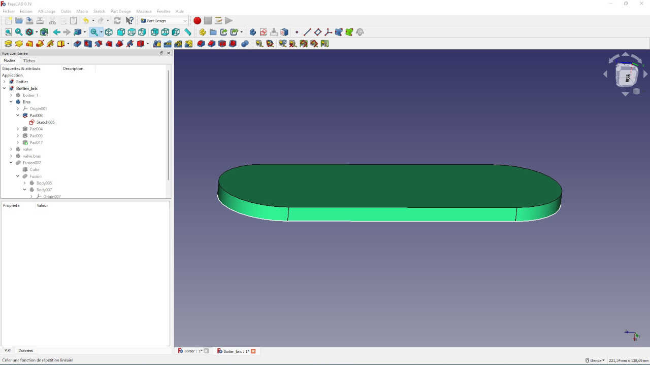
Now I will add to my arm the end cap that will be connected to the motor shaft of the first body
To finish with this body I will add a kind of wedge like two legs

I’m done with the second body, now I’ll move on to the third one which will be the valve
I will try to make a model that will look like the valve below
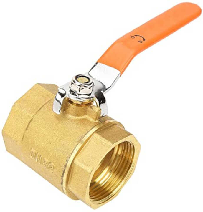
let go!
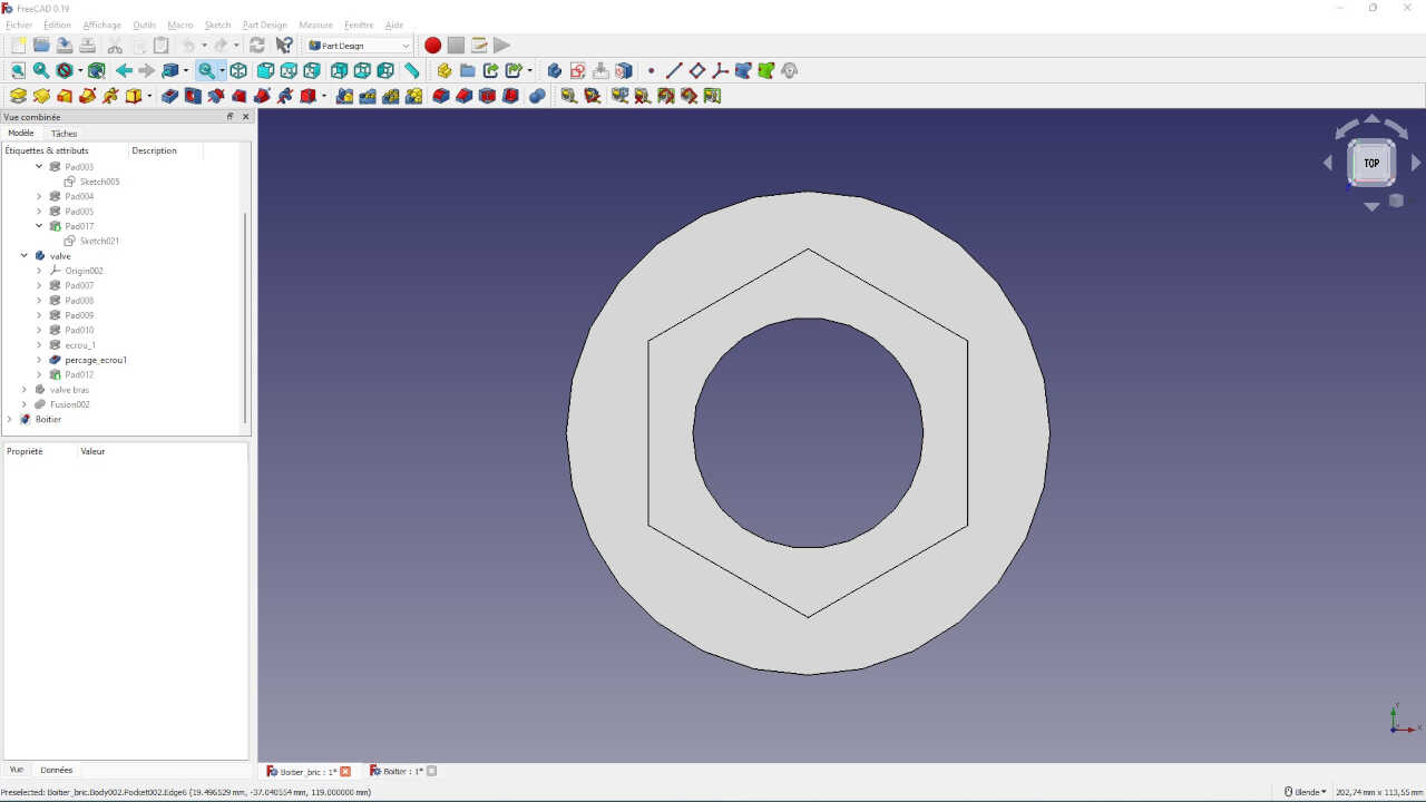
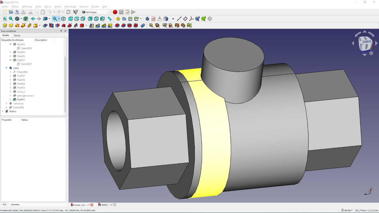
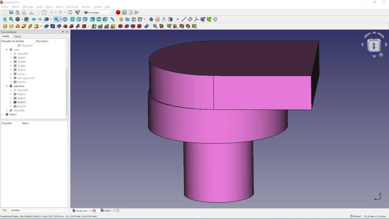
so I start by creating a new body then I will sketch one of the nut ends that I will protrude. After I get the nut shape out I will protrude the cylindrical shape in the middle and finish by protruding the nut shape on the other end.
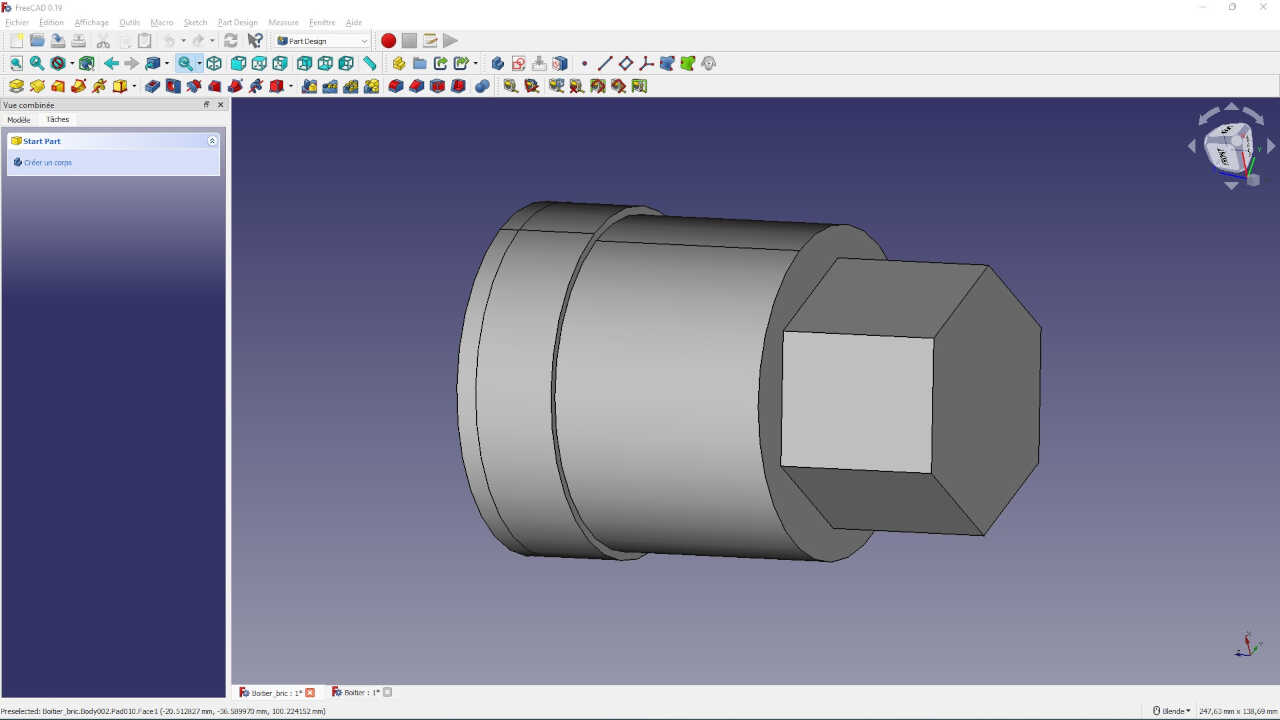

I will now drill a hole in this shape and add a cylindrical protrusion for the valve head to open and close
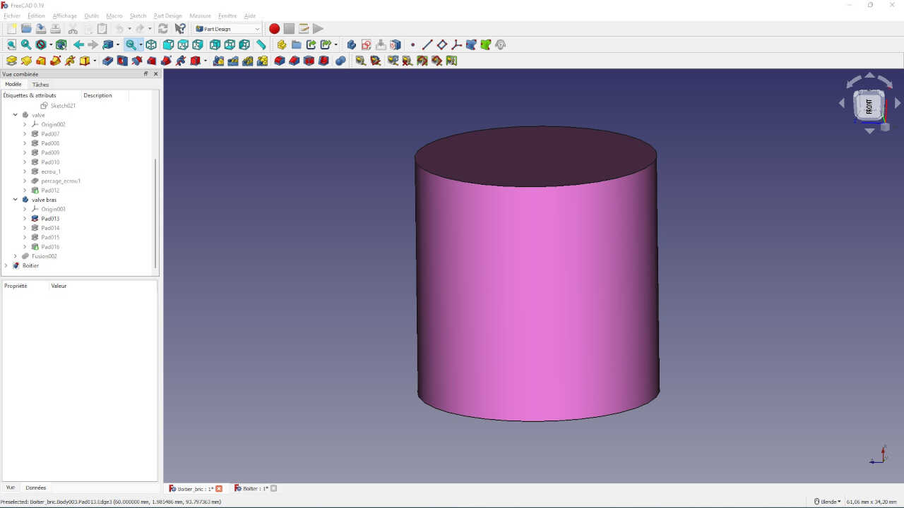
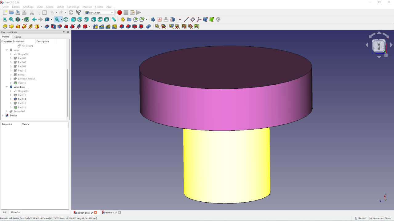
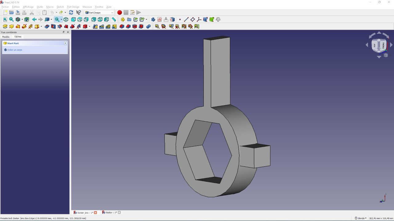
I have the valve but without the head that allows to open and close. So this head will be my fourth part.
For this part I will only make protusions of material.
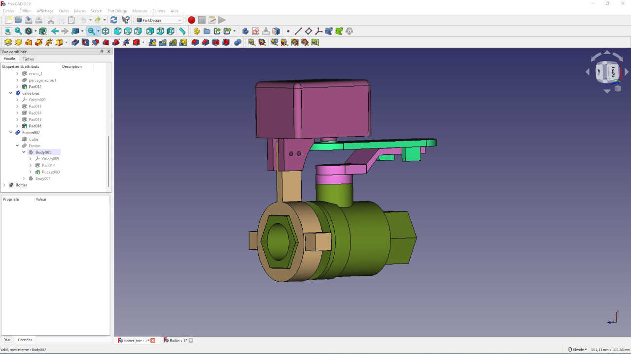
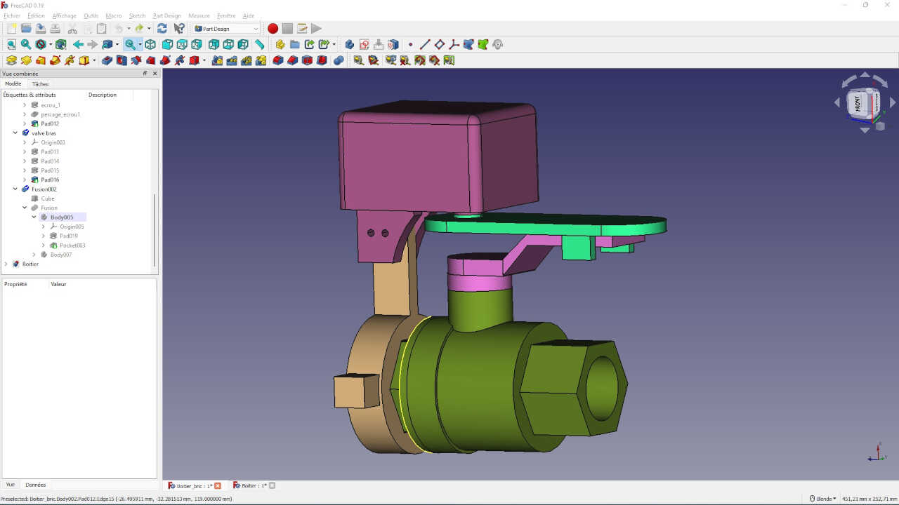
We are now at the last body, the fifth which will be the part that will connect the box (the first shape) to the valve (the third shape).
we finally have all our shapes, but they are not joined together.
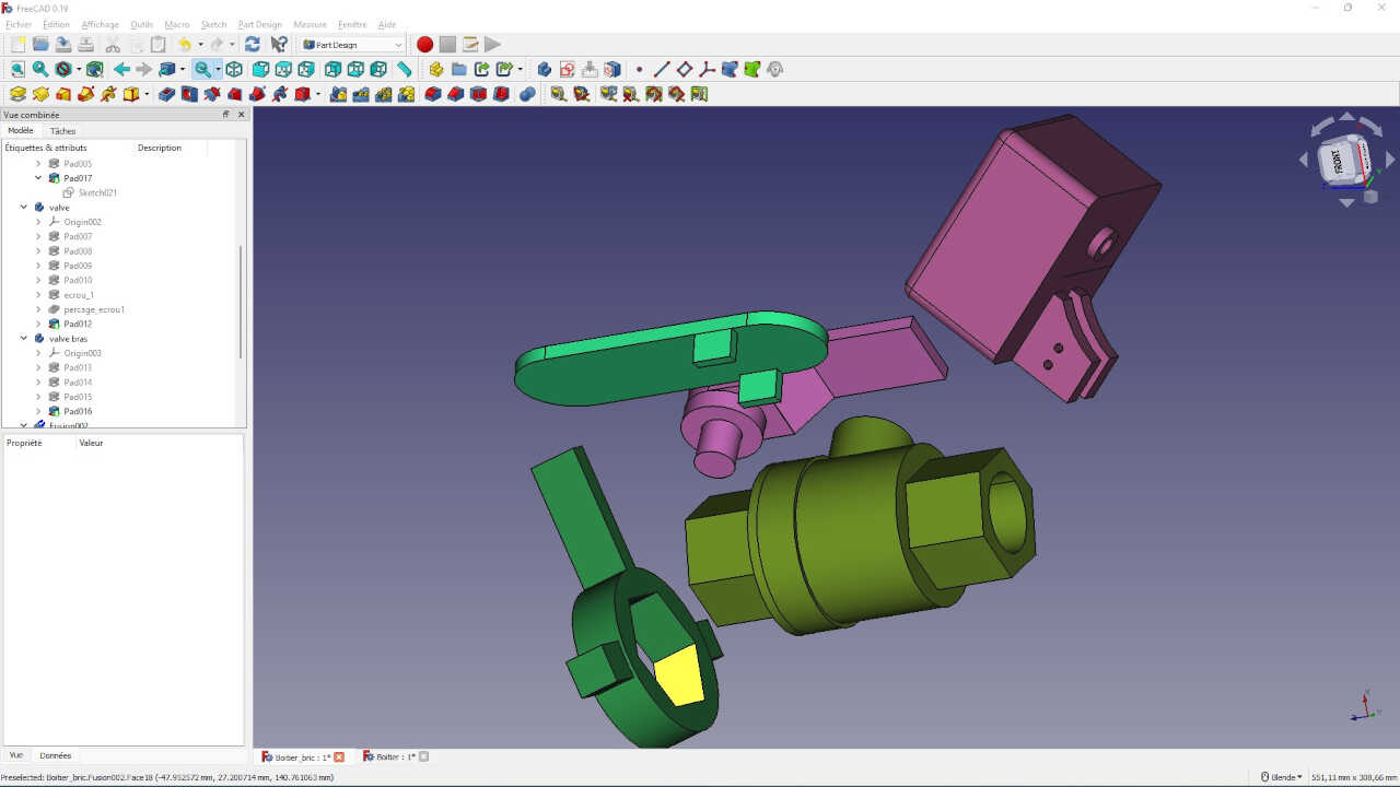
To put them in order I right click on a shape in the combined view and then click on transformation. On the shape appears several allowing to place the shape in the space.
![]()
I use this process to put everything in order.
Files
What went wrong/What went wel
Overall, everything went well. It was a week without rest since I was an amateur in 3D and 2D modeling. So I followed a lot of tutorials on YouTube to get by. But in the end, I learned a lot in one week and I’m very proud of it.