17. Machine design
Welcome to this week’s assignment, in this week’s task we were asked to design and build a working machine in our various labs. Let me introduce you to Zoro as we chose to name the hot wire foam cutting machine we built. We chose to build this machine to enable us to make quick mold making templatees using styrofaom and quickly prototype some ideas using inexpensive and recycled styrofoam.
group assignment
-
design a machine that includes mechanism+actuation+automation+application
-
build the mechanical parts and operate it manually
-
document the group project and your individual contribution
Hero Shot
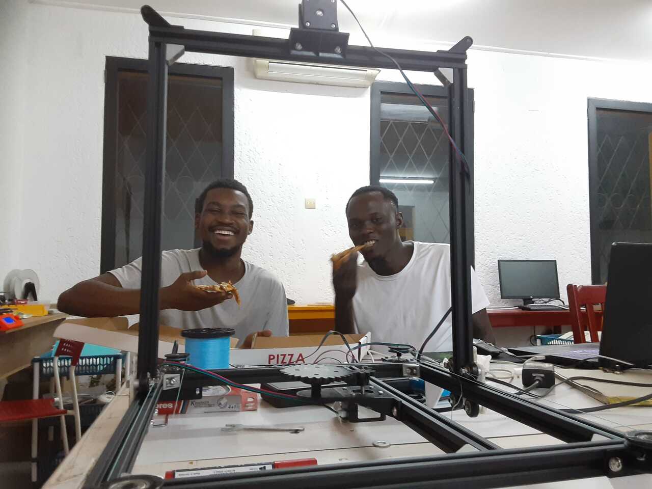 image: having a little fun with pizza after completing the build.
Description
Zoro is a hot wire foam cutting machine built using the 3-axis CNC principle. It is powered by and arduino coupled with a gerber CNC shield. I was responsible for building the frame and assembling the mechanical parts of Zoro.
-
The frame was built using eight 20x20x400mm aluminum pieces with some torque screws and 90 degree pieces to lock them together.
-
Four stepper motors were used for the 3-axis, 2 for the x-axis, 1 for the y-axis and 1 for the z-axis.
-
six pulleys were modeled in solidworks and 3d printed.
-
special servo motor mounts were designed and printed.
 Image: the exploded parts of Zoro before assembly.
CAD models of parts
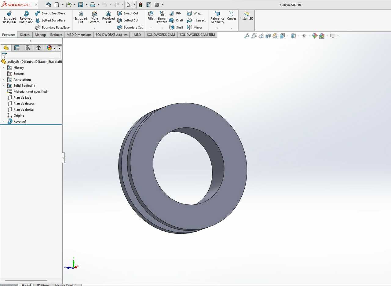 image: pulley design
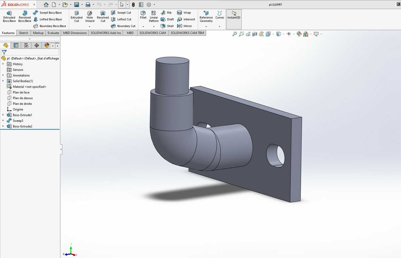 image: arm to hold the pulley on the horizontal axis
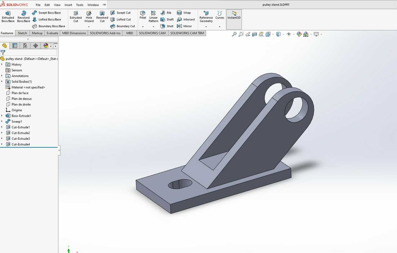 image: vertical axis pulley holder
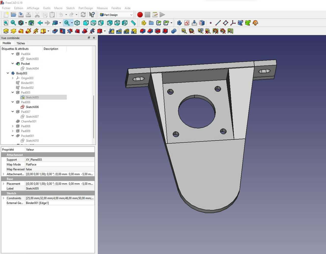 image: this is a motor mount for the rotating axis that will form the 3rd axis of Zoro
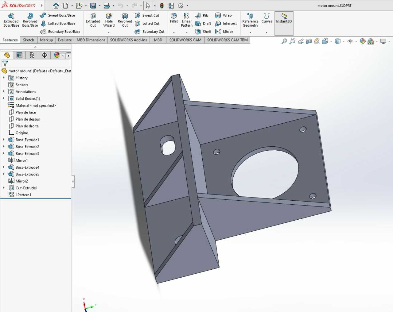 image: motor mont for all the motors in the X and Y axis of Zoro
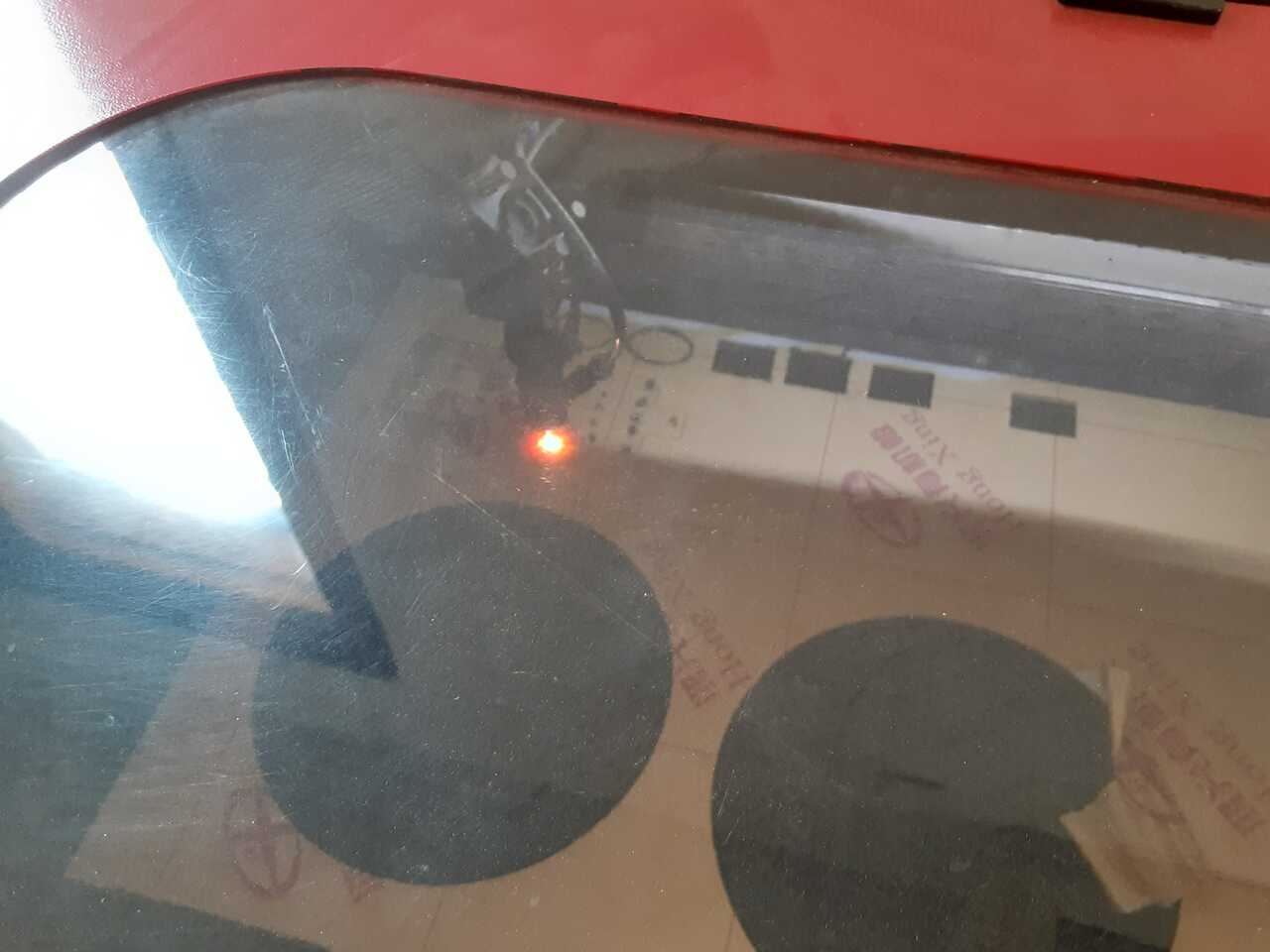 image: laser cutting the table for the rotating axis which will be the bed for all models.
Assembly
Image: the exploded parts of Zoro before assembly.
 In the image above you can see me starting the assembly of the frame of Zoro.
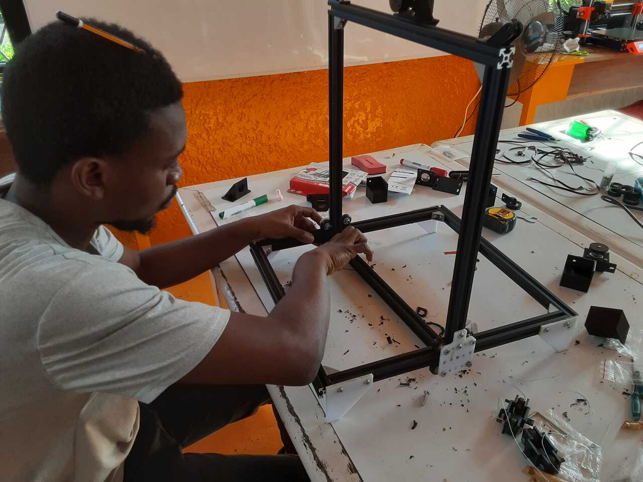 In the image above you can see me mid-way through the assembly of Zoro. fun fact, I was so focused to an extent that I forgot a pencil in my hair and spent close to 10 minutes looking for that pencil in the lab.
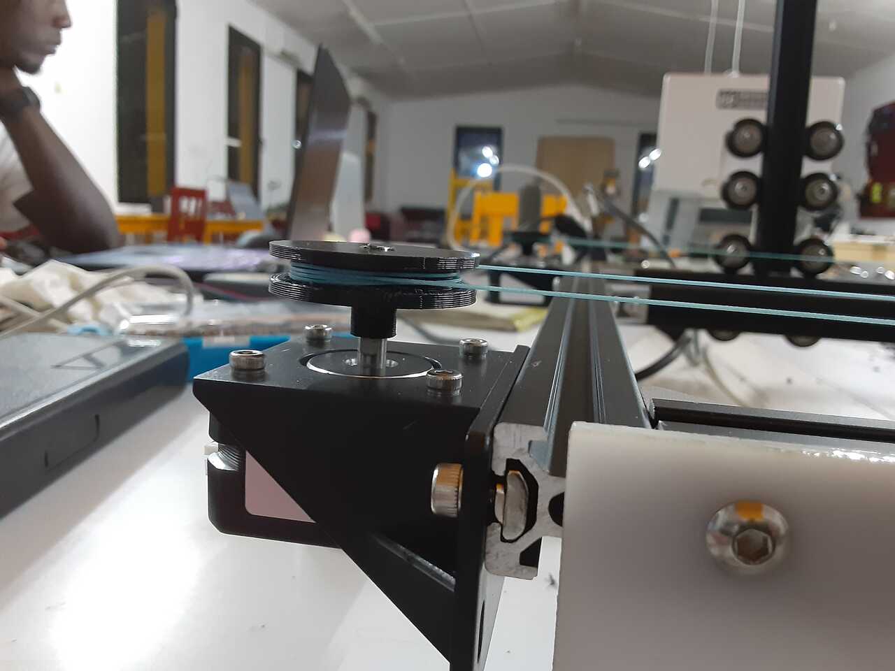
you can see me testing the mechanism for the vertical axis in the video above. The lines were wound in opposite directions so as the pulley moves clockwise there is movement in the positive side of the axis and vice versa if the pulley moves counter-clockwise there is movement in the negative direction of the vertical axis.
In the video above, we were testing the heating element before the final adjustments were made.
The two pictures below shows up-close shots of the horizontal axis mechanism. The 3D-printed pulley and the fishing line.


Link
If you are interested in see and knowing the other parts/processes of Zoro being built, you can see the conception and birth of zoro on our lab website
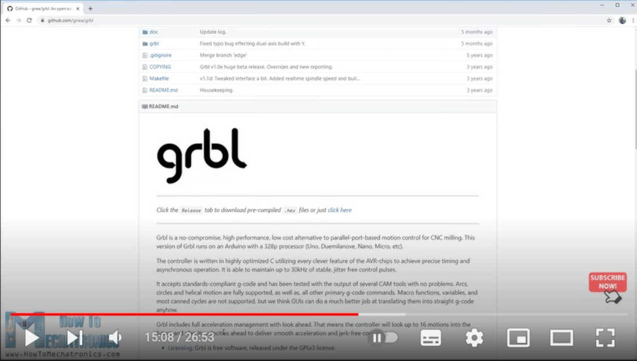
the programming was doing following this tutorial on youtube.
Summary
This week I got to use my mechanical brain(hihi), it went smoothly but if given the chance I would replace the fishing line I used for the horizontal axis with a suitable belt to retain the tension and carry the right amount of force needed. The vertical axis too could be revisited and improved upon by finding a suitable replacement for the fishing line. Apart from these everyting does not need any upgrade.