12. input devices
Welcome to this week’s assignment. In this week’s journey, we will go throught the process of my board responsible for my input devices come to reality. So this week we were tasked with a group assignment and an individual assignment. individual assignment: measure something: add a sensor to a microcontroller board that you have designed and read it group assignment: probe an input device’s analog levels and digital signals
Group ASsignment
In this week’s group task, we were asked to probe an input device’s analog levels and digital signals and below are the results of the task.
In the video above, it shows the readings when the input device was probed using the osciloscope in the lab. This was reading the analog value of the Soil moisture sensor, the line depicting the variation in signal as the level is changed. The value is between 0 -5v
The video above shows the readings when digital signals where being applied. The values are either 0v or 5v it does not vary as the moisture level varies.
Hero Shots
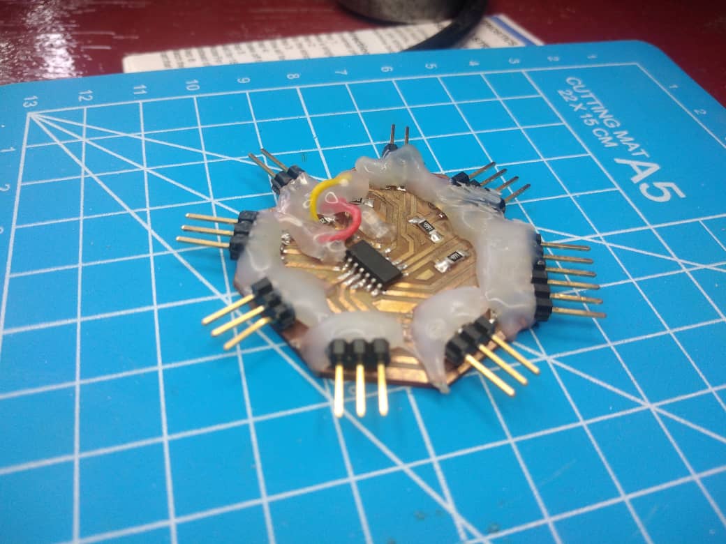

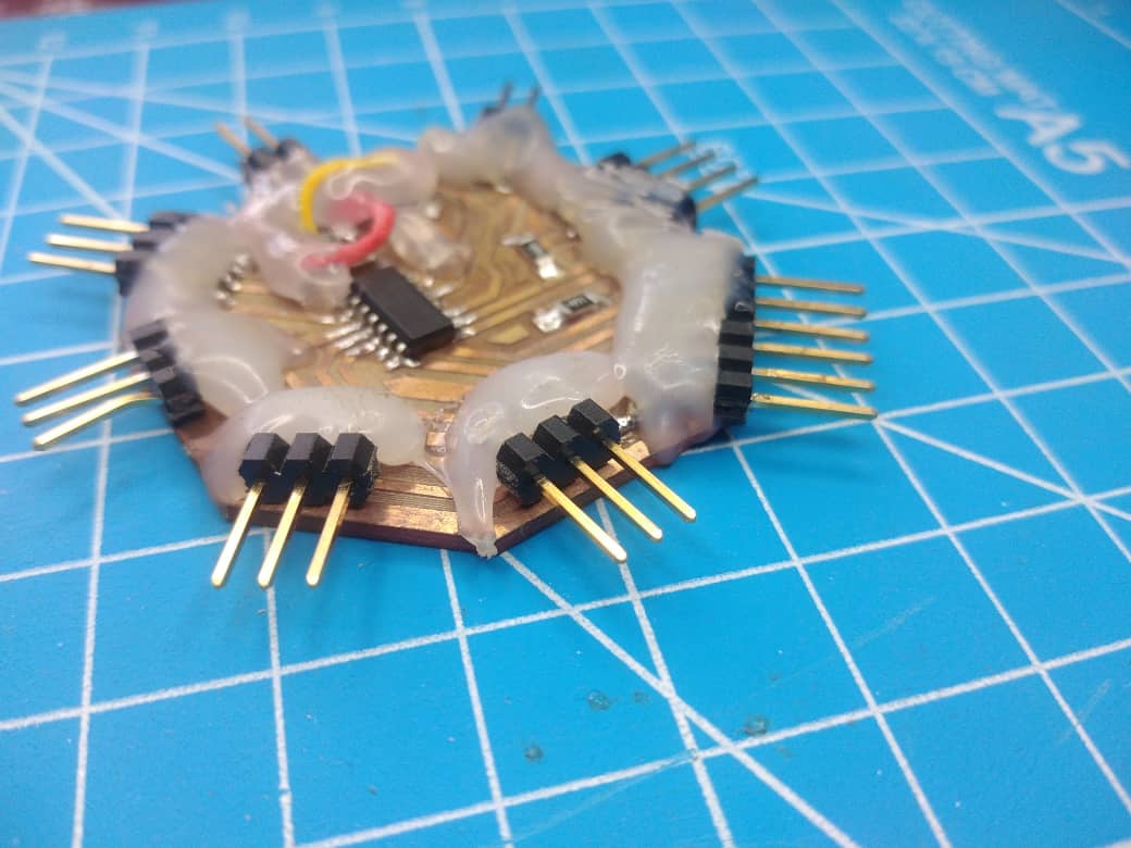 Ps: I put hot glue on the connectors to make them sturdy and strong. so the board does not appear nice.
Individual Assignment
From the individual task ‘ measure something: add a sensor to a microcontroller board that you have designed and read it’, I decided to whip up a new board design solely for the input devices I will be using for my final project. This is a brief description of the board we will be making.
-
It will be powered by an ATtiny 1614 microchip.
-
It will accomodate 5 input devices namely.
-
2 moisture sensors.
-
2 DHT22 humidity&temperature sensors.
-
1 Photo resistor.
Now with this brief description let’s move straight to the design of the board.
Board Design
The first thing is to download the KiCAD software if you have not downloaded it yet because that is the software I will be using for all my PCB boards designs. I use this software it design the PCB from the schematics to the 3D design.
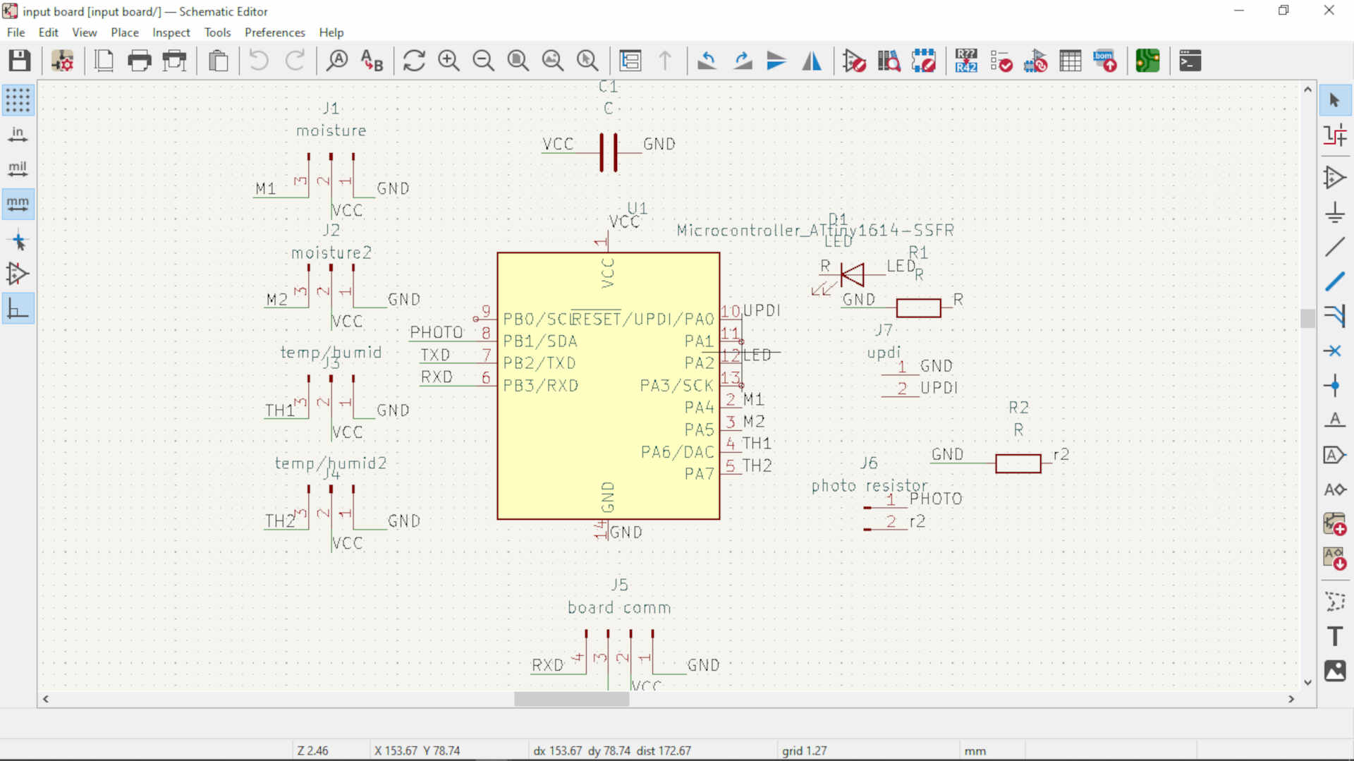 in the image above shows the schematic diagram of the circuit with the symbols of the various electrical components.
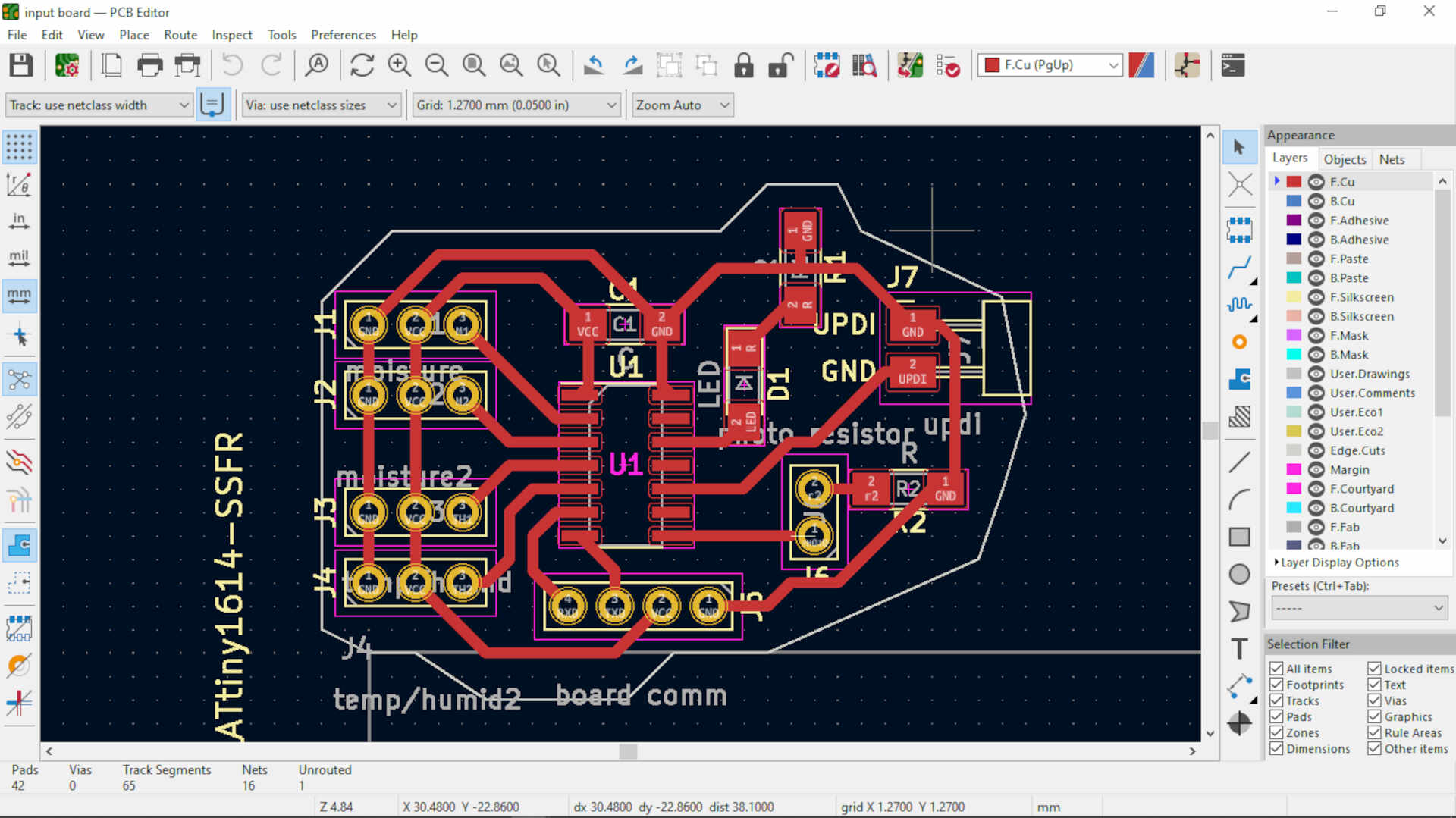 as you can see in this image, I rearranged the components in to a much more organized circuit in the PCB editor window of the software and then I specified the edge cut of the board.
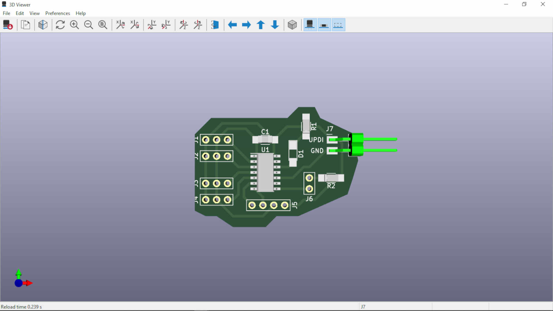
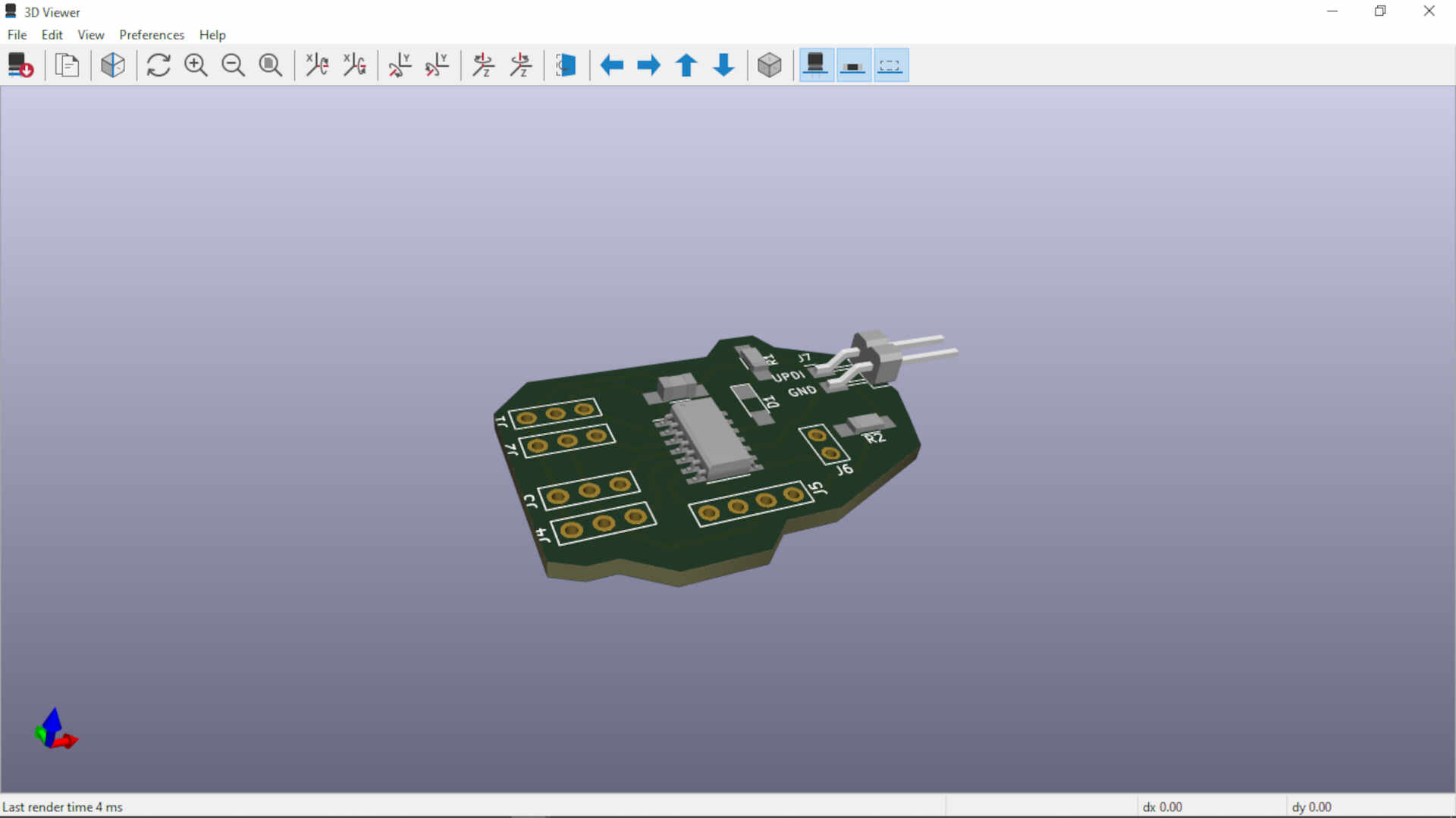 In these two images above, you can see the design rendered in 3D to have a preview of how the board will look when it is milled out and the components soldered onto it.
Production
We move to the production of the board, in this stage I used the FlatCAM software to convert the files in to CNC jo files for our CNC machine to do the job of producing the desired designs. There are some checks and cautions to take note before milling out your board.
-
you need to cross check in the PCB editor to make sure that none of the traces will have contact when it is milled out by your machine.
-
you need to make sure that there are enough spaces for your components to sit freely and space for you to be able to solder without you burning or damaging any other component.
 in this image, I was creating the cnc job file for the copper traces of the circuit
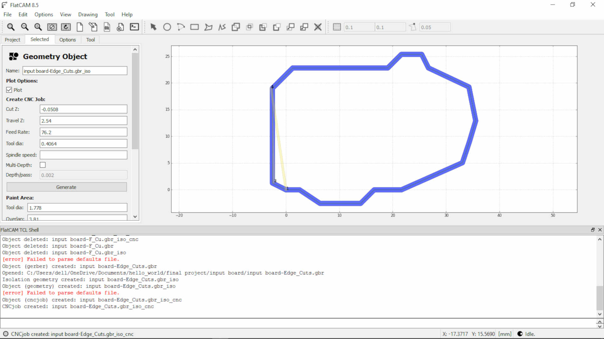 this is me creating the CNC job file for the edge cut of the PCB using FlatCAM
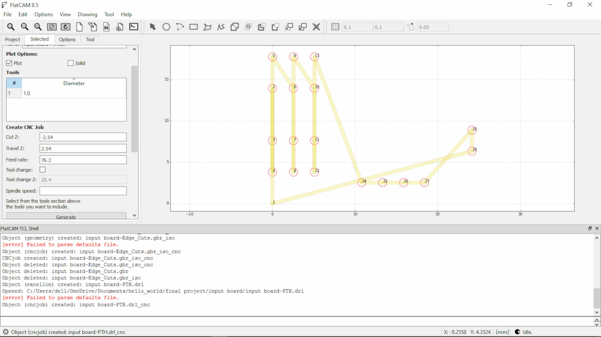 In this picture, The drill file for the through hole was generated in KiCAD and now I was generating the CNC job file for it using FlatCAM.
In the images below, it shows the program used to control the CNC machine and the various files as it worked on milling the PCB out.
 Copper traces
 Edge cuts
 drilling of holes.
 in this picture, you can see two boards milled. the board at the bottom had issues pertaining to the traces having contact. I checked the PCB design and made some corrections and milled the top board with no issues this time.
Now moving onto putting all the components together by soldering.
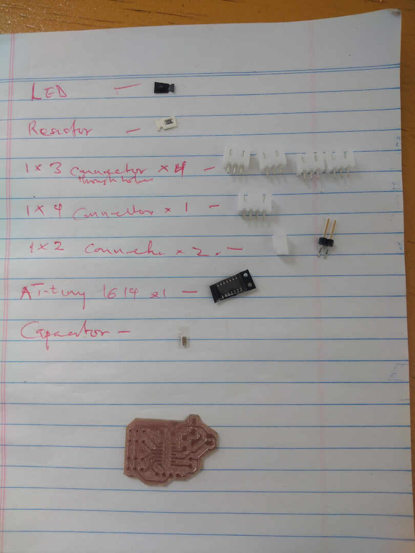 this image shows the list of components on a sheet of papper.
- capacitor 1uf 50V
- 10k ohm resistor
- 4990 ohm resistor
- ATtiny 1614 microchip
- LED
- 1x3 vertical connectors x4
- 1x4 vertical connectors x1
- 1x2 horizontal connector


Programming
I used the arduino IDE to write programs to test my sensors. I wrote two programs, one to test the moisture sensors and the other to test the DHT22 temperature and humitdity sensor.
Moisture Program
this is a simple program to test if the sensor is woring and all connections are working. the program turn of an onboard led when the moisture is in the required range. I made use of the If and Else clause statement.
int led_pin =9;
int sensor_pin =1;
void setup() {
pinMode(led_pin, OUTPUT);
pinMode(sensor_pin, INPUT);
}
void loop() {
if(digitalRead(sensor_pin) == HIGH){
digitalWrite(led_pin, HIGH);
} else {
digitalWrite(led_pin, LOW);
delay(1000);
}
}
Temperature Program
this is a simple program to test if the sensor is woring and all connections are working. the program turn of an onboard led when the Temperature is in the required range. I made use of the If and Else clause statement.
#define DHTPIN1 3
#define LED 9
DHT dht1(DHTPIN1, DHTTYPE);

float hum1;
float temp1;

void setup() {
  // put your setup code here, to run once:
dht1.begin();
pinMode(LED, OUTPUT);
}

void loop() {
  // put your main code here, to run repeatedly:
hum1  = dht1.readHumidity();
    temp1 = dht1.readTemperature();

    if (temp1>=32)
    {
      digitalWrite(LED, HIGH);

    }
    else
{
  digitalWrite(LED, LOW);
  }

}
files
input_copper_trace input_edge_cut input_drill
Things changed
So I ended up changing the original design of the board to incorperate some changes. These are the changes:
- I added some resistors (10k ohm) to the SDA and SCL lines on my port for the I2C communication and the reconfigured the photo cell.
below are the images to show the changes
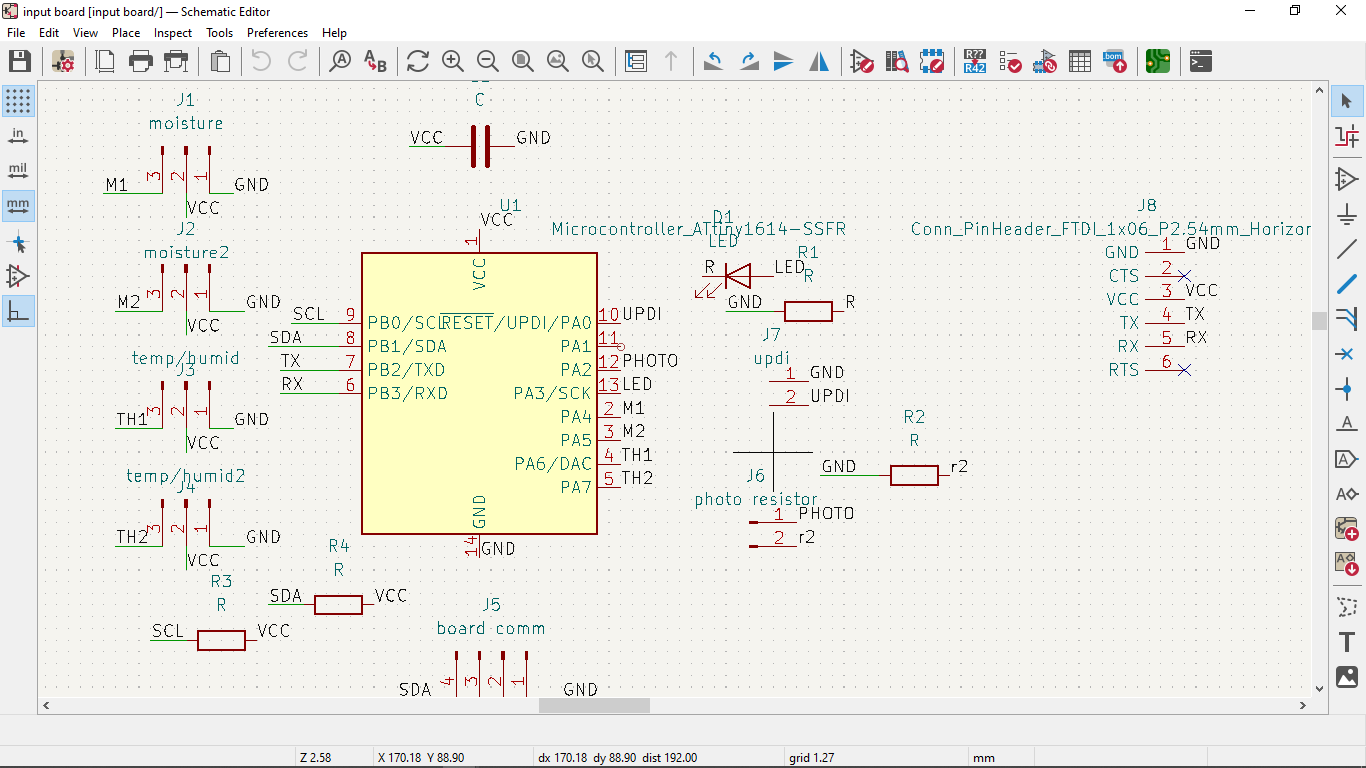 image: schematics
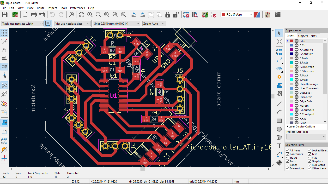 image: PCB design
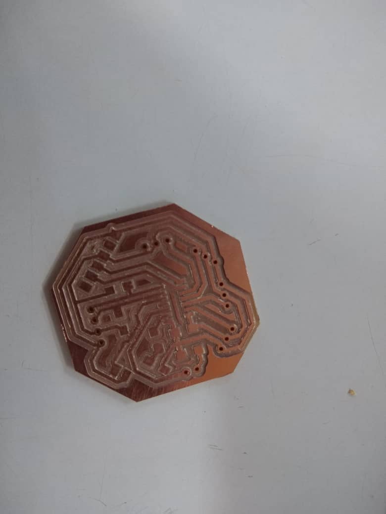 image: the newly designed board after milling
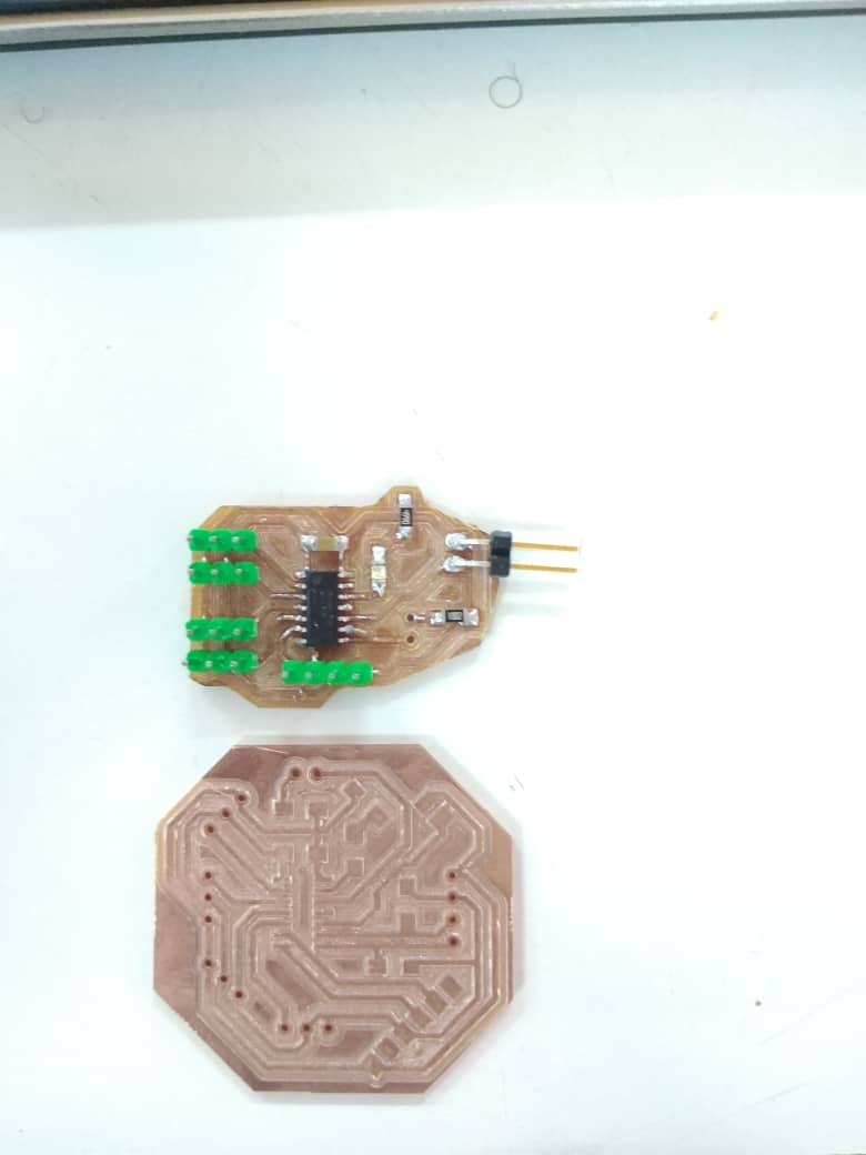 image: the newly designed board side-by-side comparison with the old board
The code was changed as well
#include<Wire.h>
#include<DHT.h>
#define DHTTYPE DHT22
#define DHTPIN1 2
#define DHTPIN2 3

int temp;
int hum;
int temp2;
int hum2;
int moisture;
int moisture2;

void setup() {
  // put your setup code here, to run once:
dht1.begin();
dht2.begin();
Wire.begin();
Serial.begin(9600);
}

void loop() {
 // put your main code here, to run repeatedly:
temp = dht1.readTemperature();
hum  = dht1.readHumidity();
moisture = 1023 - analogRead(sensorpin);
moisture = map(moisture,7,910,0,100);
moisture2 = 1023 - analogRead(sensorpin2);
moisture2 = map(moisture2,7,910,0,100);
Serial.println("temp & Humidity: ");
Serial.println(temp);
Serial.println(hum);
Serial.println("temp2 & Humidity2: ");
Serial.println(temp2);
Serial.println(hum2);
Serial.print("mositure: ");
Serial.println(moisture);
Serial.print("mositure2: ");
Serial.println(moisture2);

delay(1000);
}
Reading the input
In my first board I did not add an FTDI connection terminal, so I was not able to read the serial of the input. After modifying the input board for my final project was then I could read the data at last so below is a snipet of the reading in the serial monitor.
In the video above, it shows values, temp and humidity which is read from one DHT22 sensor connected to the board and shows moisture and moisture2 which is read from two soil moisture sensors connected to the board.
Wrapping up
this week was a great one, I got to better my arduino programming skills and designed a board for my final desing input board. Not forgetting I improved on my soldering skills too.