6. 3D Scanning and printing
The assignment for this week was to learn how to characterise and use 3D printers, learn how to 3D scan an object, and to design a part that can not be easily made subtractively and print it using a 3d printer. As with most weeks, there were group assignments and individual assignments. The details of which are listed below.
Group assignment:
Test the design rules for your printer(s) Document your work and explain what are the limits of your printer(s) (in a group or individually)
Individual assignment:
Design and 3D print an object small (few cm3, limited by printer time that could not be easily made subtractively) 3D scan an object (optionally print it)
Hero Shots


Group Assignment
For the group assignment we had to test the design rules of our printer, document our work, and explain the limits of our printers. Before diving in to the assignment, i will first begin by discussing the equipment.
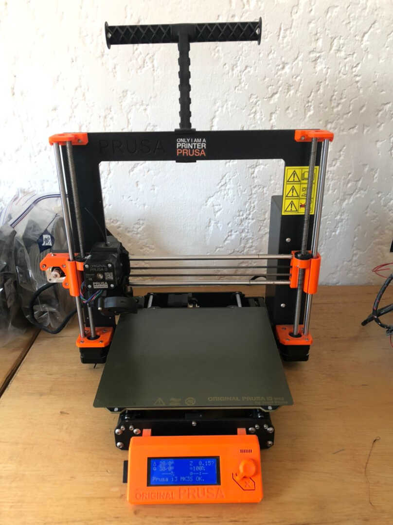 Image: Prusa i3-Mk3s printer.
The printer used was the Prusa i3-mk3s 3d printer. To check out it’s specification and possibily order one click_here.
The stl files that were used for the group work can be found here
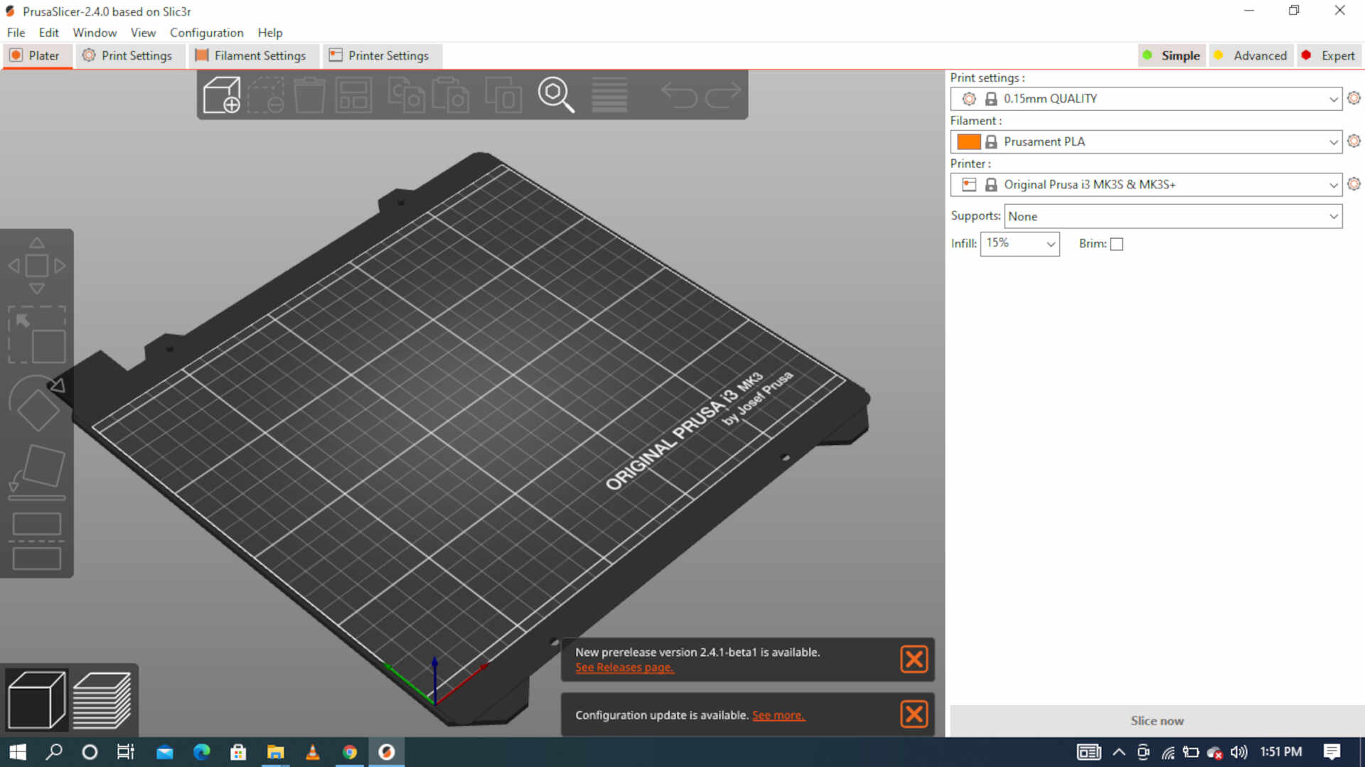
the prusa comes with it’s own slicing software.
3D printer test
Clearance
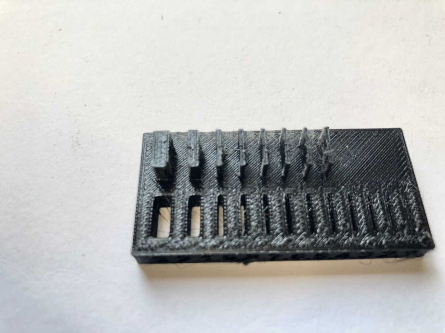
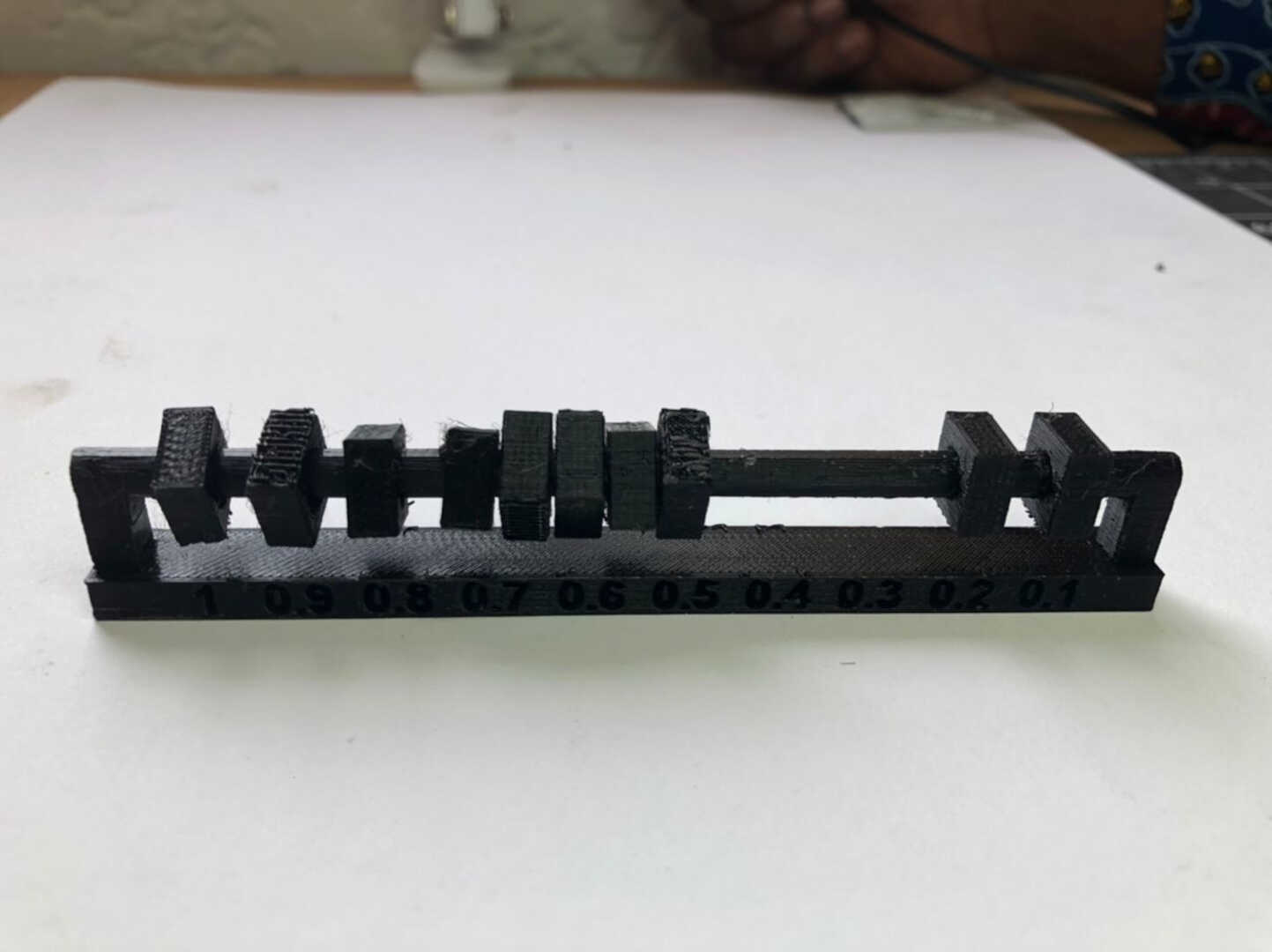 image: this image shows the gap clearance capability of our 3D printer. This gives me a list of clearance to choose from if I want to print something with a revolving joint. The clearance started from 0.1mm to 1mm with an increment of 0.1mm. 0.1mm and 0.2mm were not able to move but the rest were moving freely.
Surface finish
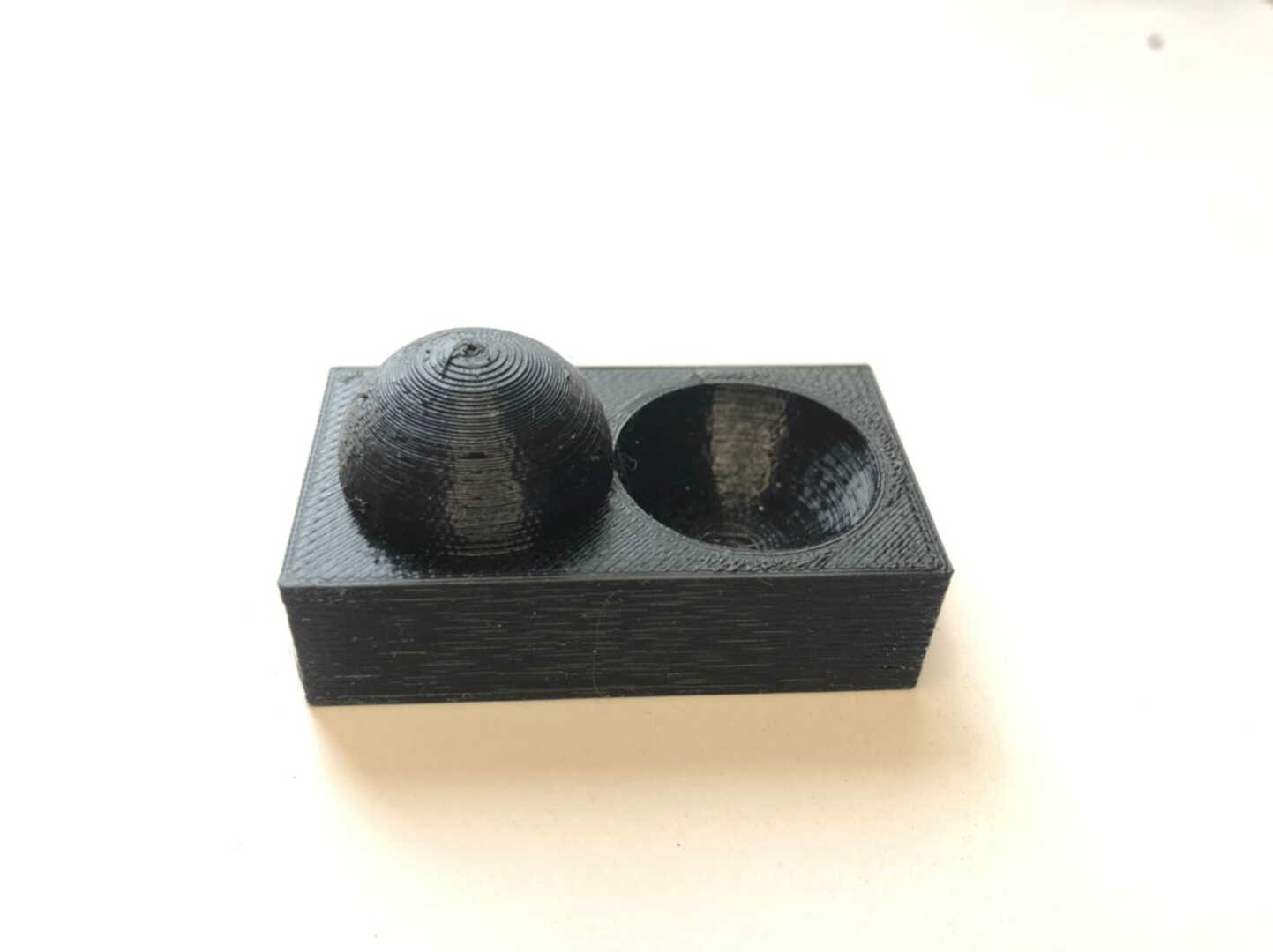 This image shows this test, we printed a piece that had gradually increasing overhangs to test what angle of departure can be used without supports. The results of the test were that we were able to print to an angle of about 30 degrees before having issues with the print results.
Anisotrophy
 These images shows the results of the test, the difference between the accuracy of the printer when it is printing horizontally, vs. when it is printing vertically is characterized. This is done by printing a part that is equal in both the horizontal and vertical directions and comparing the actual print dimensions.
Overhang
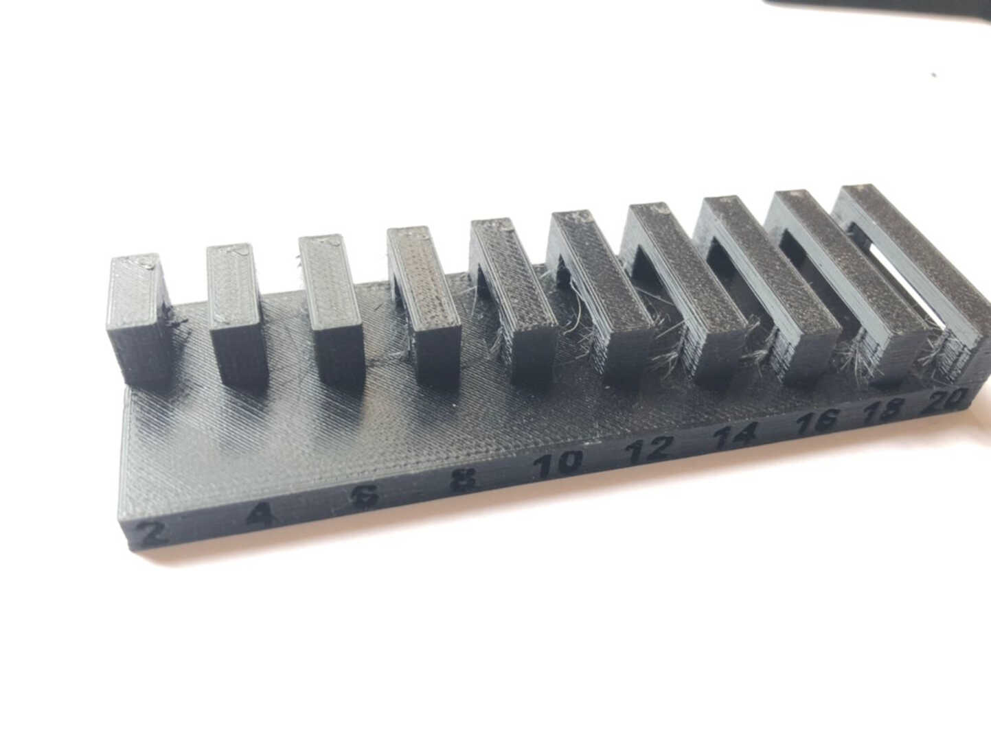
 This test looked at how long of an overhang can be used before the print begins to fail. In this test, overhangs of increasing length are printed and the length at which the print becomes messy is the limit. The results for our printer indicated that the limit is approximately 3 mm of overhang.
Dimensions
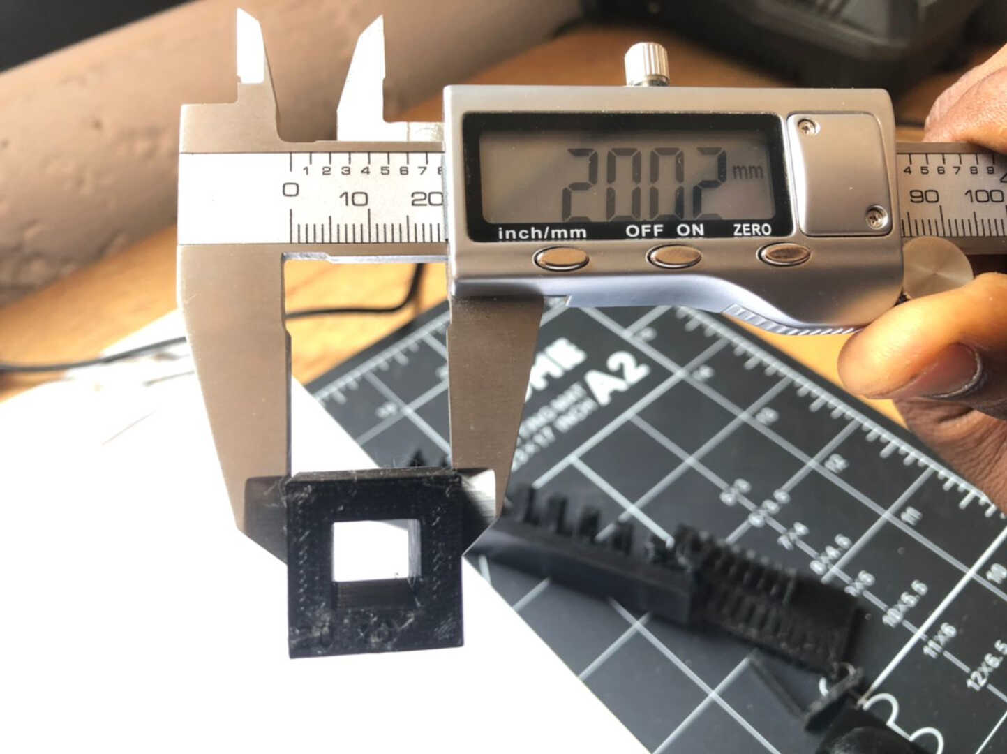
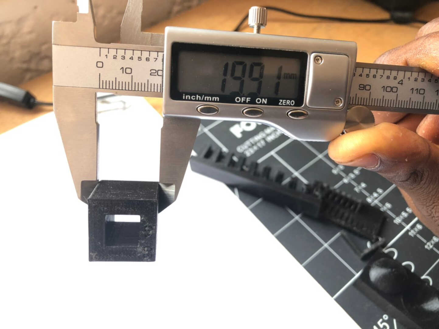

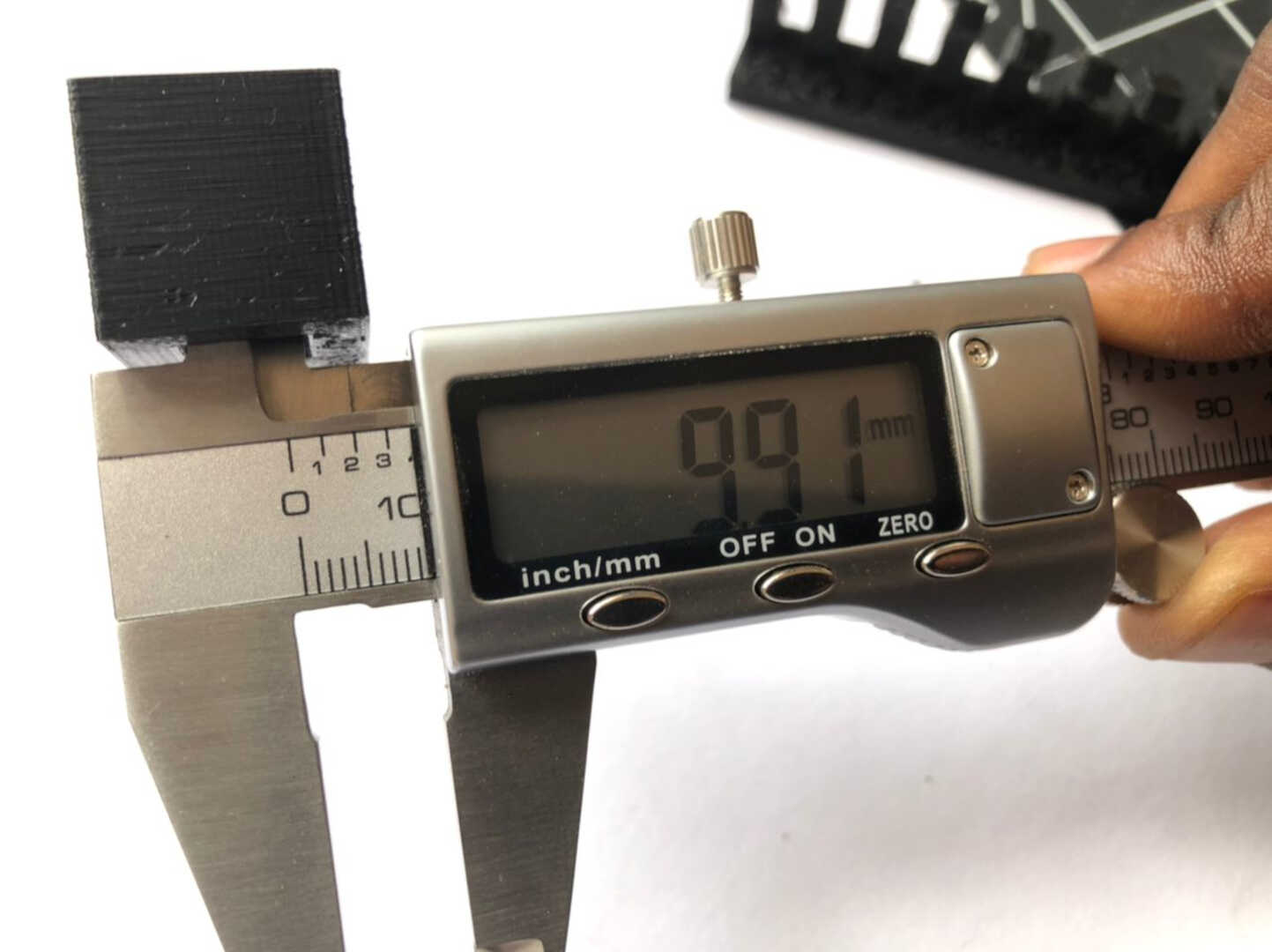
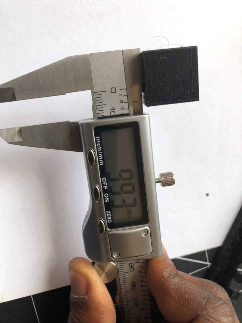
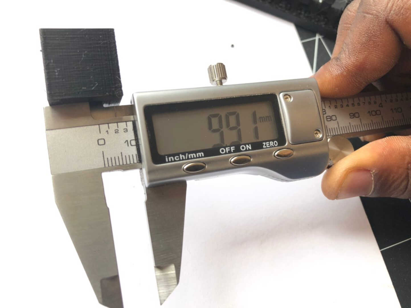
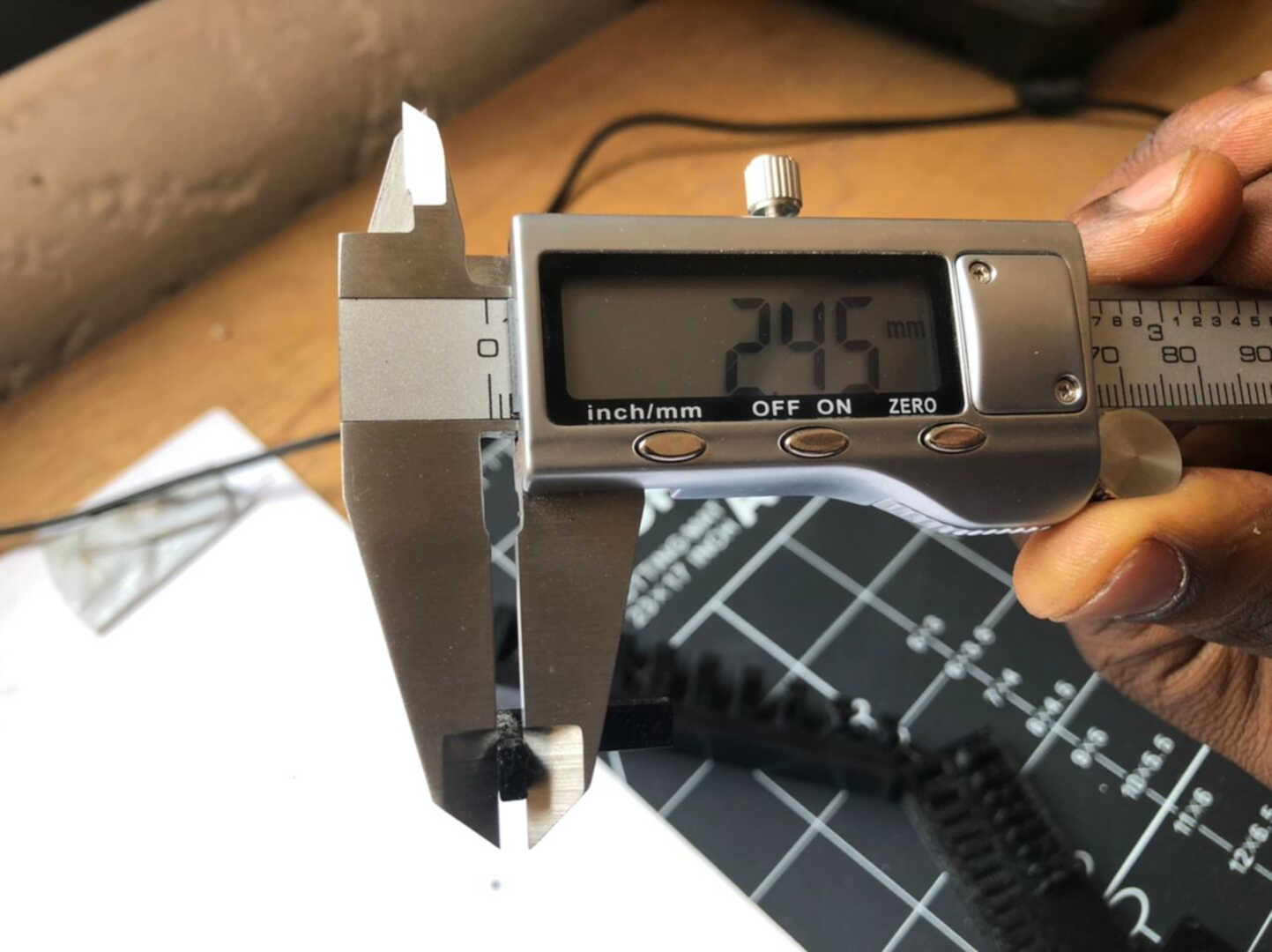
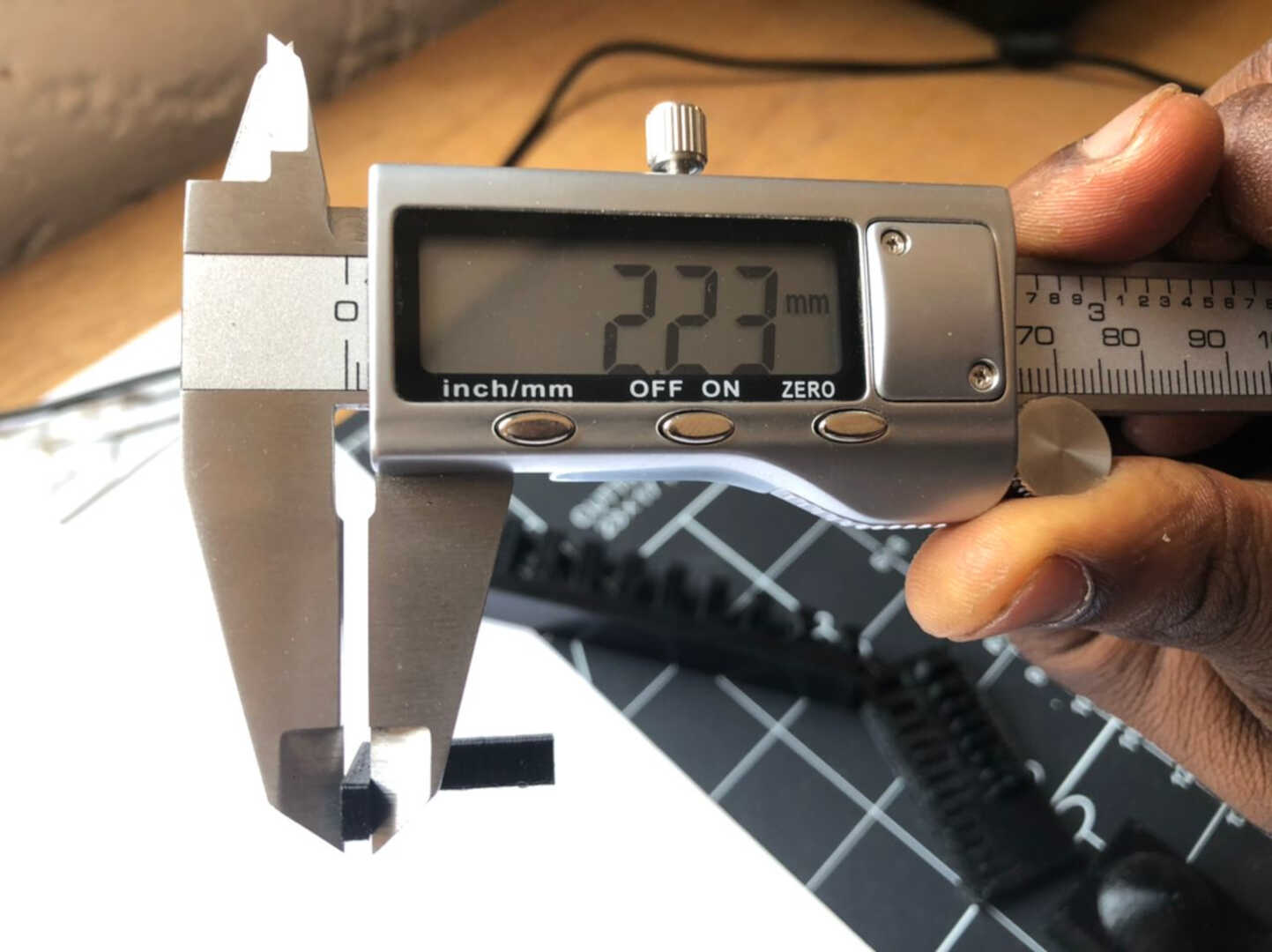
In this print, the accuracy of the dimensions is tested by comparing the printed dimensions as well against the original mesh file dimensions. This will be limited by the width of the extruded filament and the precision of the motors. The test piece had an outer width of 20 mm and an inner width of 10 mm. As demonstrated in the images below, the printer is fairly accurate with a nominally small margin of error.
Wall thickness
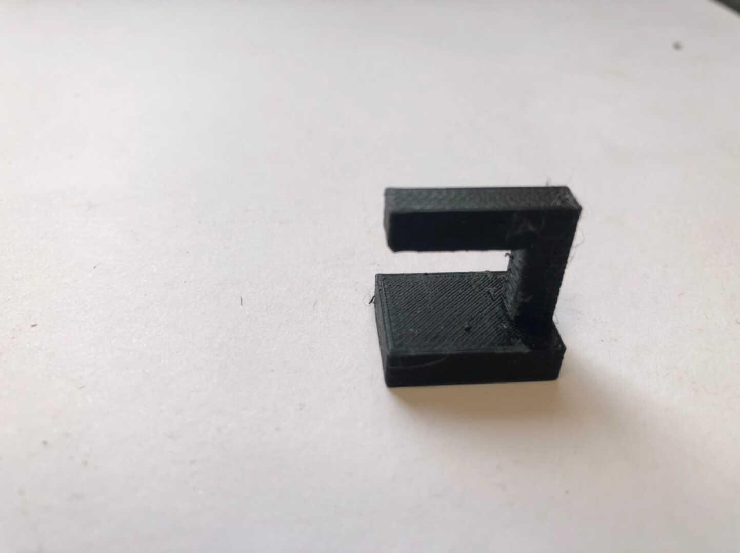
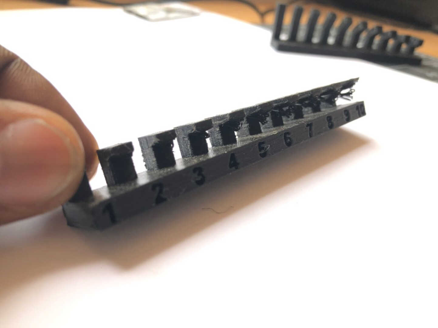
 In this test, a piece was printed in which wall thicknesses were increased in an additive manner, and the gap between two walls was also printed. The results of this test showed that a minimum thickness of around 0.8mm is required before the wall will not be able to support itself and begin to deform.
Angle
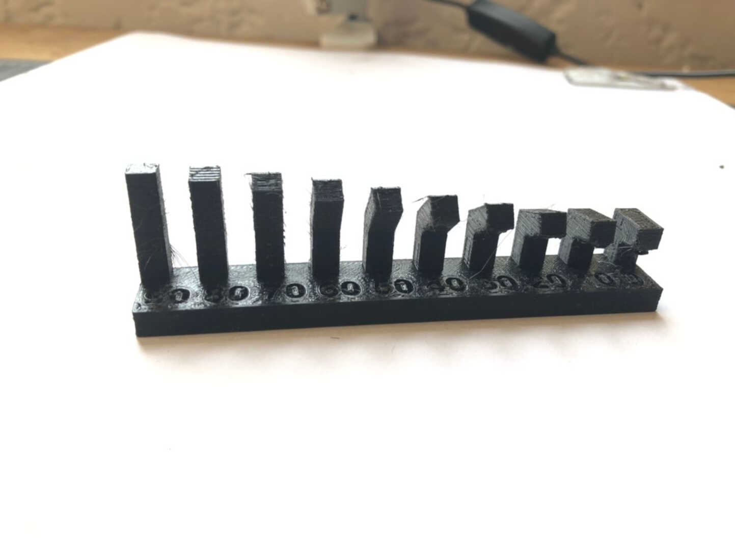 In this test, we printed a piece that had gradually increasing overhangs to test what angle of departure can be used without supports. The results of the test were that we were able to print to an angle of about 20 degrees before having issues with the print results.
Bridging
 The birdging test evaluates how far your extruder can pul a filament across a gap before drooping or sagging. In this test, the length between two posts is gradually increased. Interestingly, every gap was perfectly bridged
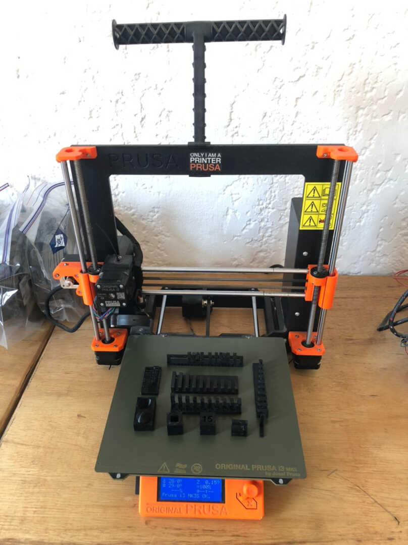
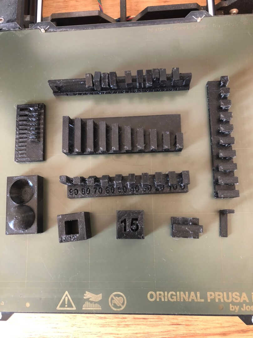
All printed tests
These images below shows all the test after printing.
Individual Assignment
We were tasked this week to 3D scan an object of our choice and optionally print it. I used a 3D sense 3D scanner which has the intel RealSense SR300 hardware.
We were also tasked to design and 3D print an object small (few cm3, limited by printer time that could not be easily made subtractively)
The Scan
I had to use the itseez3d scanner 2.0 download software to scan the object since the software that came with scanner was malfuctioning.
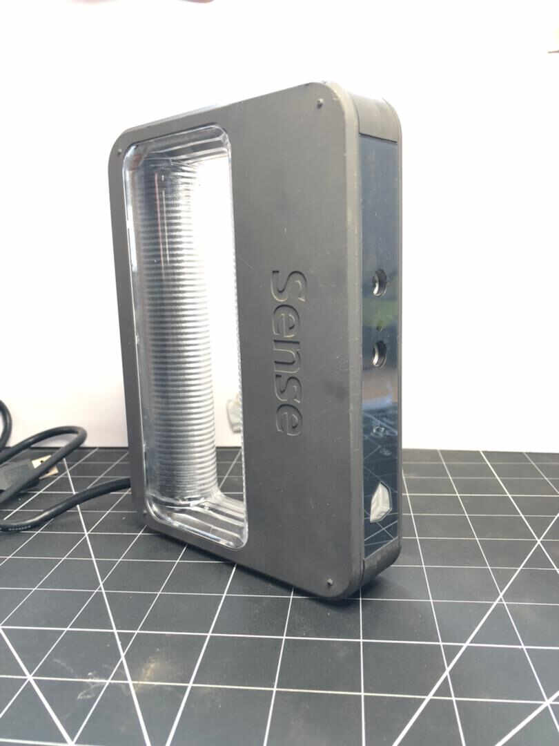
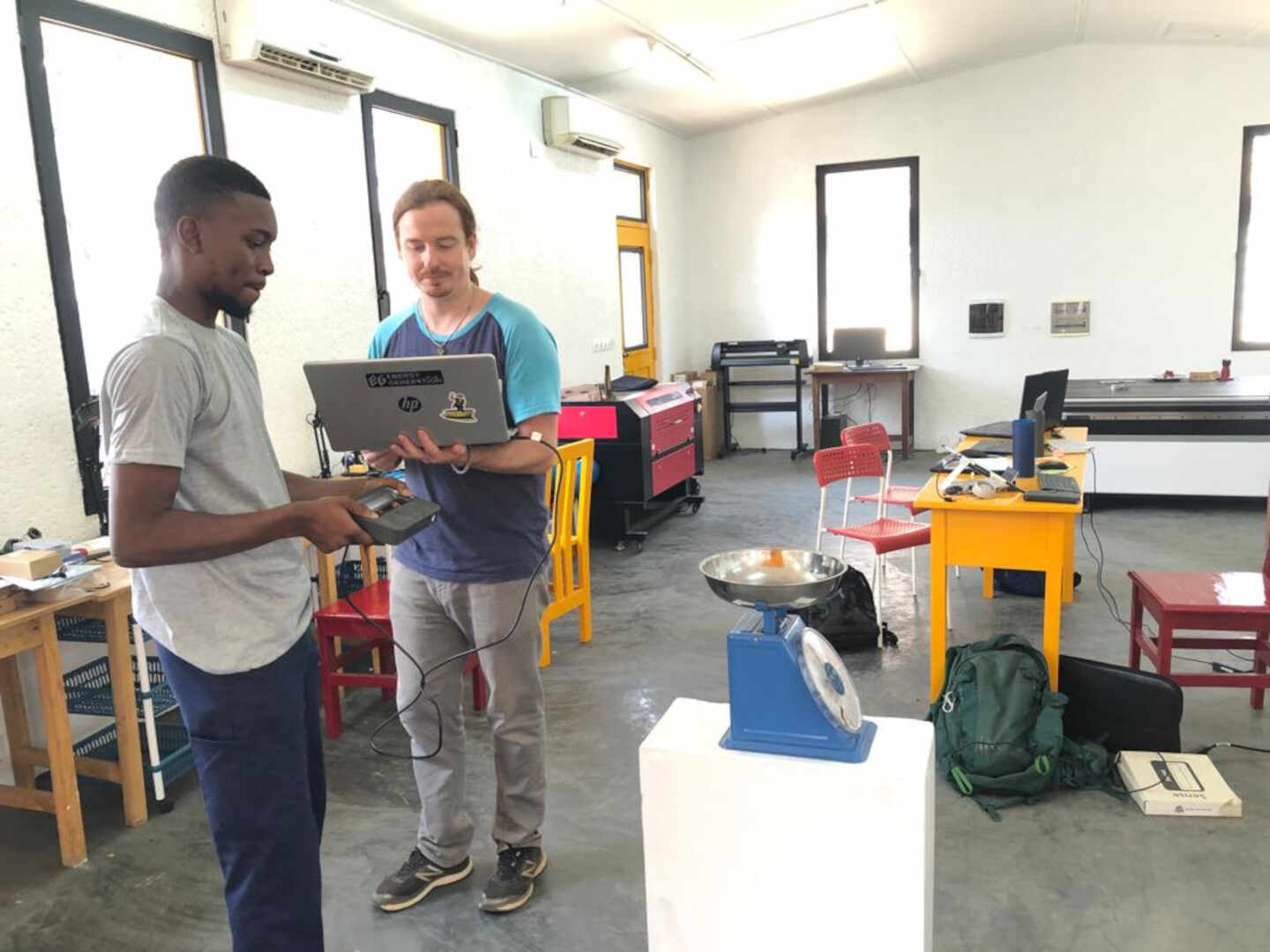 image: this is me scanning an object of choice.
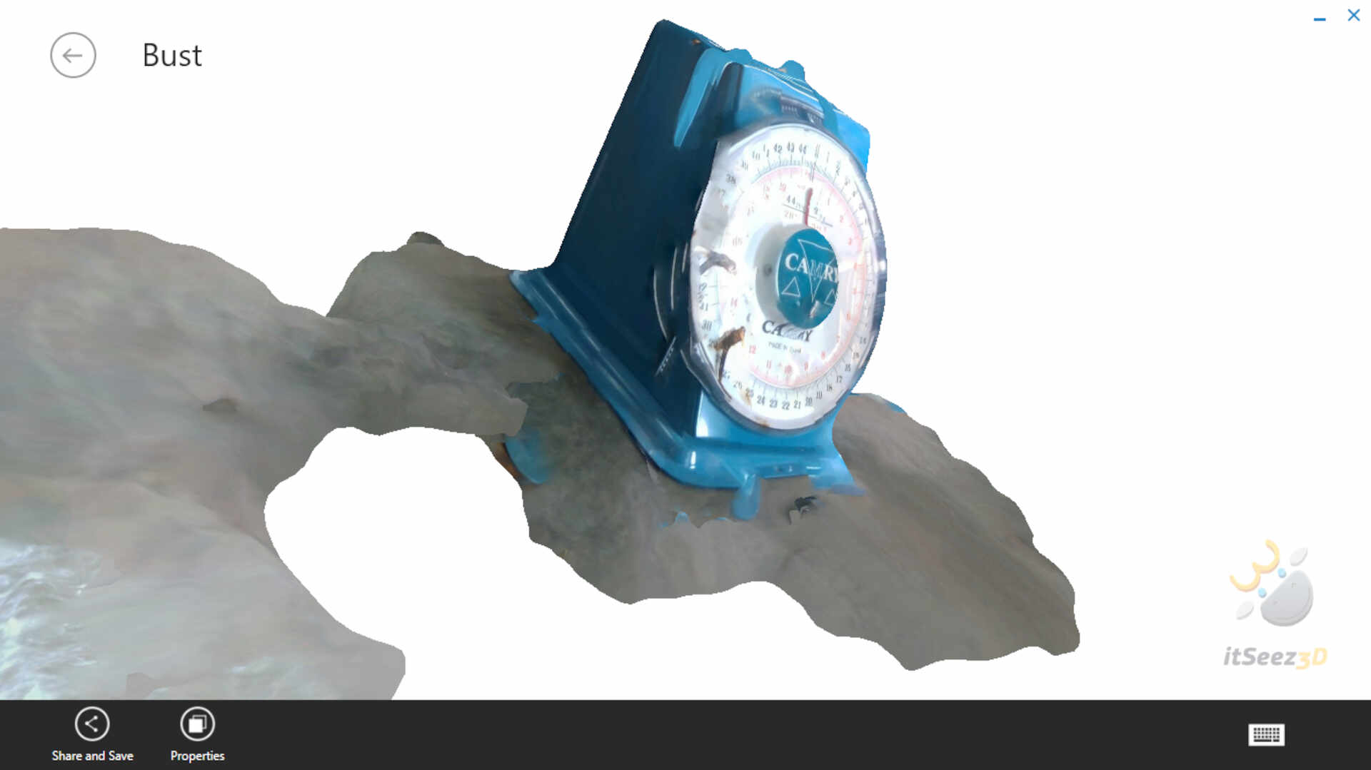
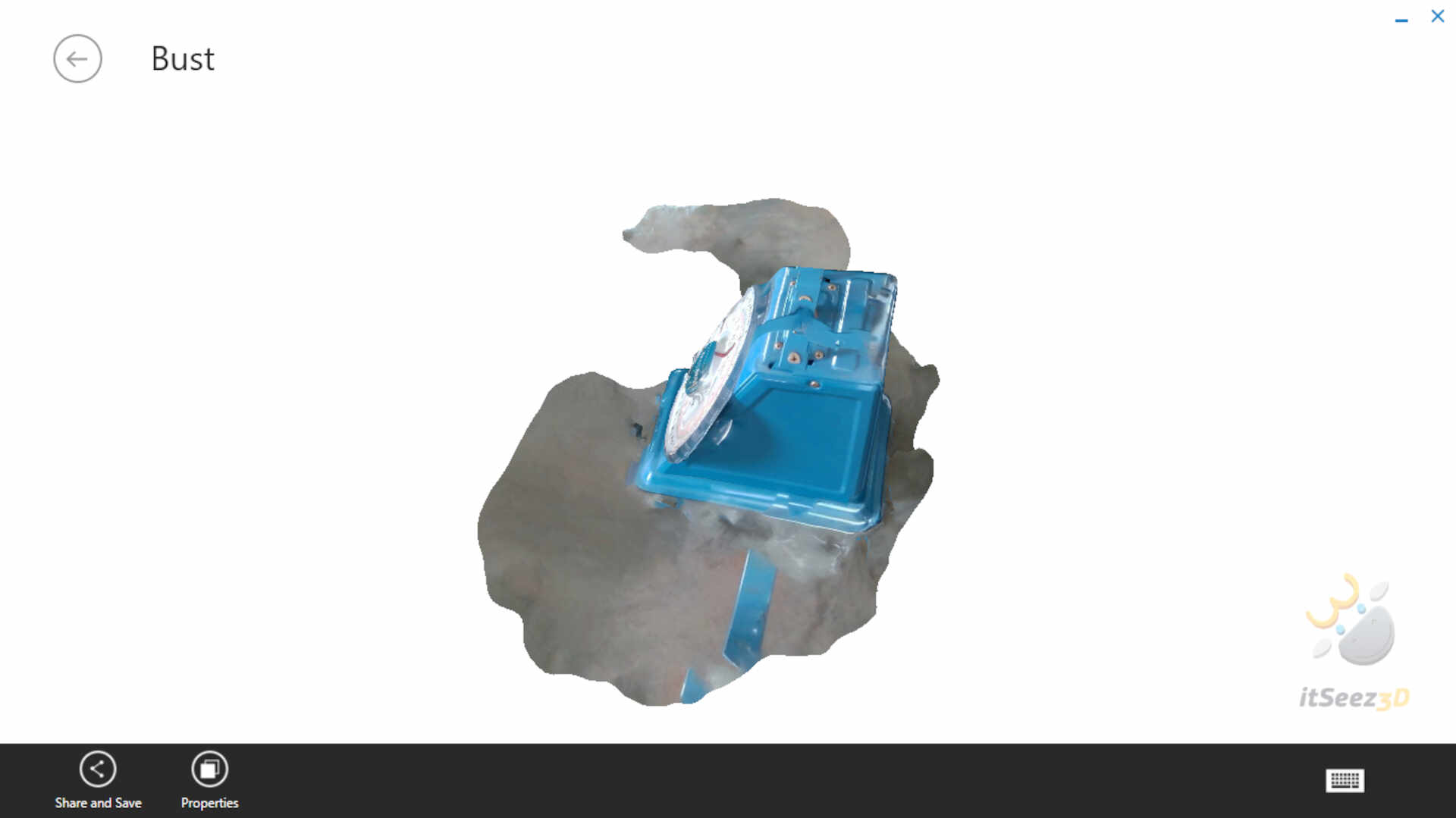
results of the scan
3D Design and Print-out
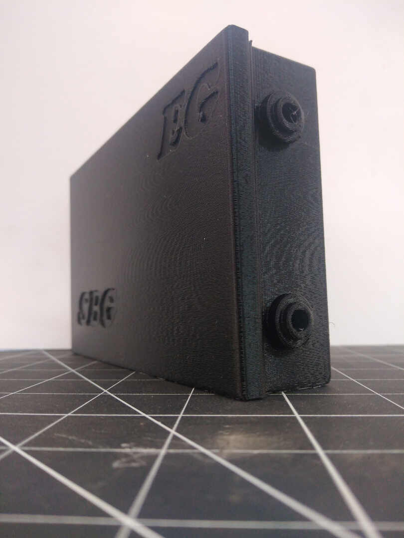
This design is a development of my week03 assignment. I used this since it is a key component for my final project. I imprinted the abbreviations of the project Smart Backyard Garden(SBG) on the lid and EG (Energy Generation).
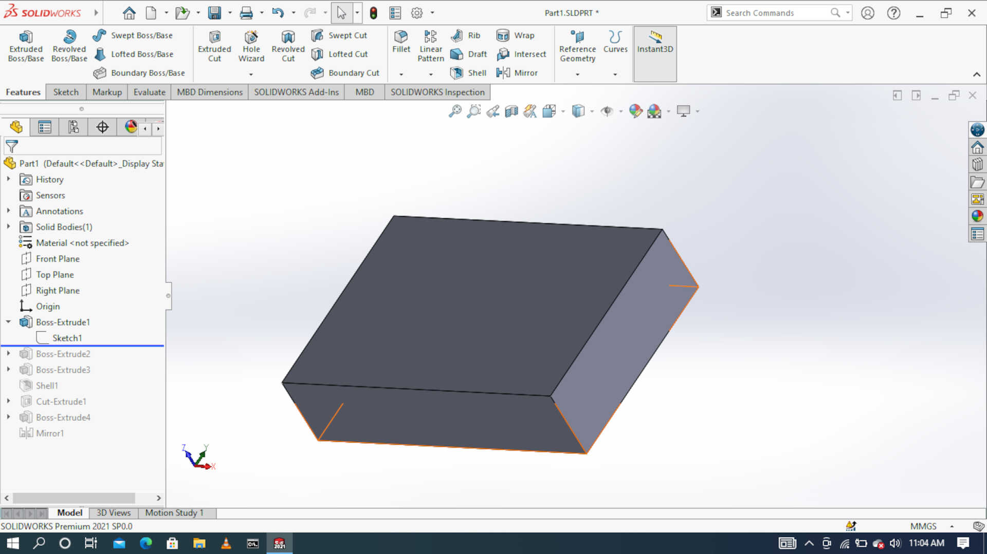 Image: Base extrusion
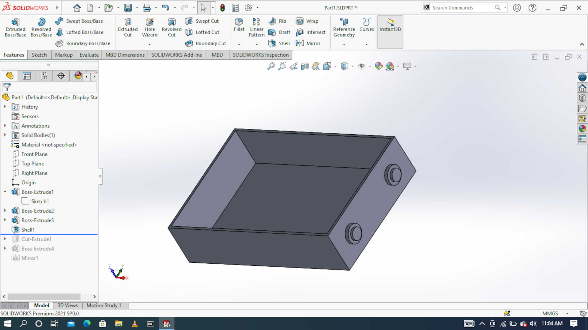 Image: Shelling to create a hollow
 Image: creating grooves for sliding
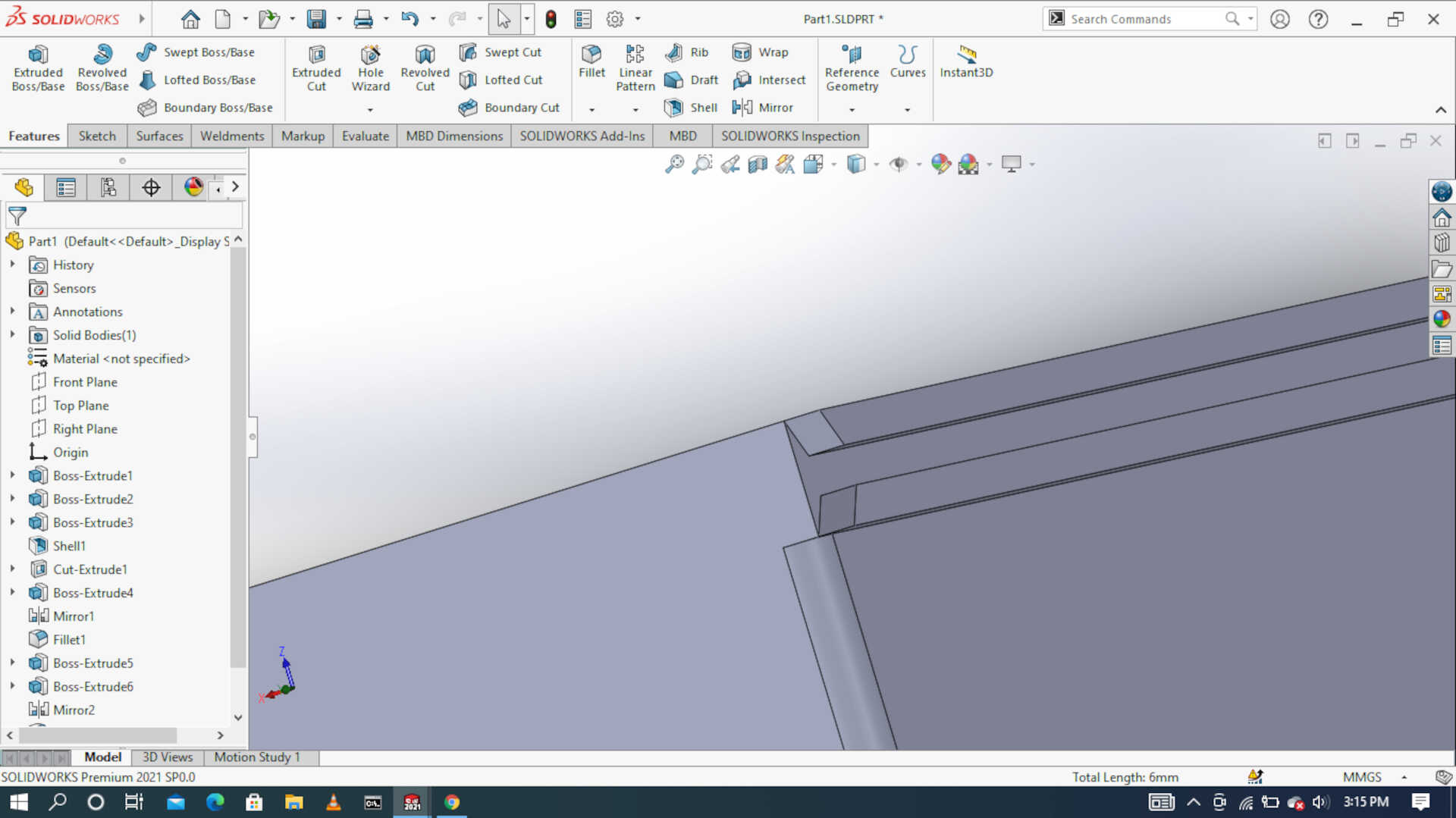 Image: adding chamfer to guide the lid rails
 Image: with the lid and text
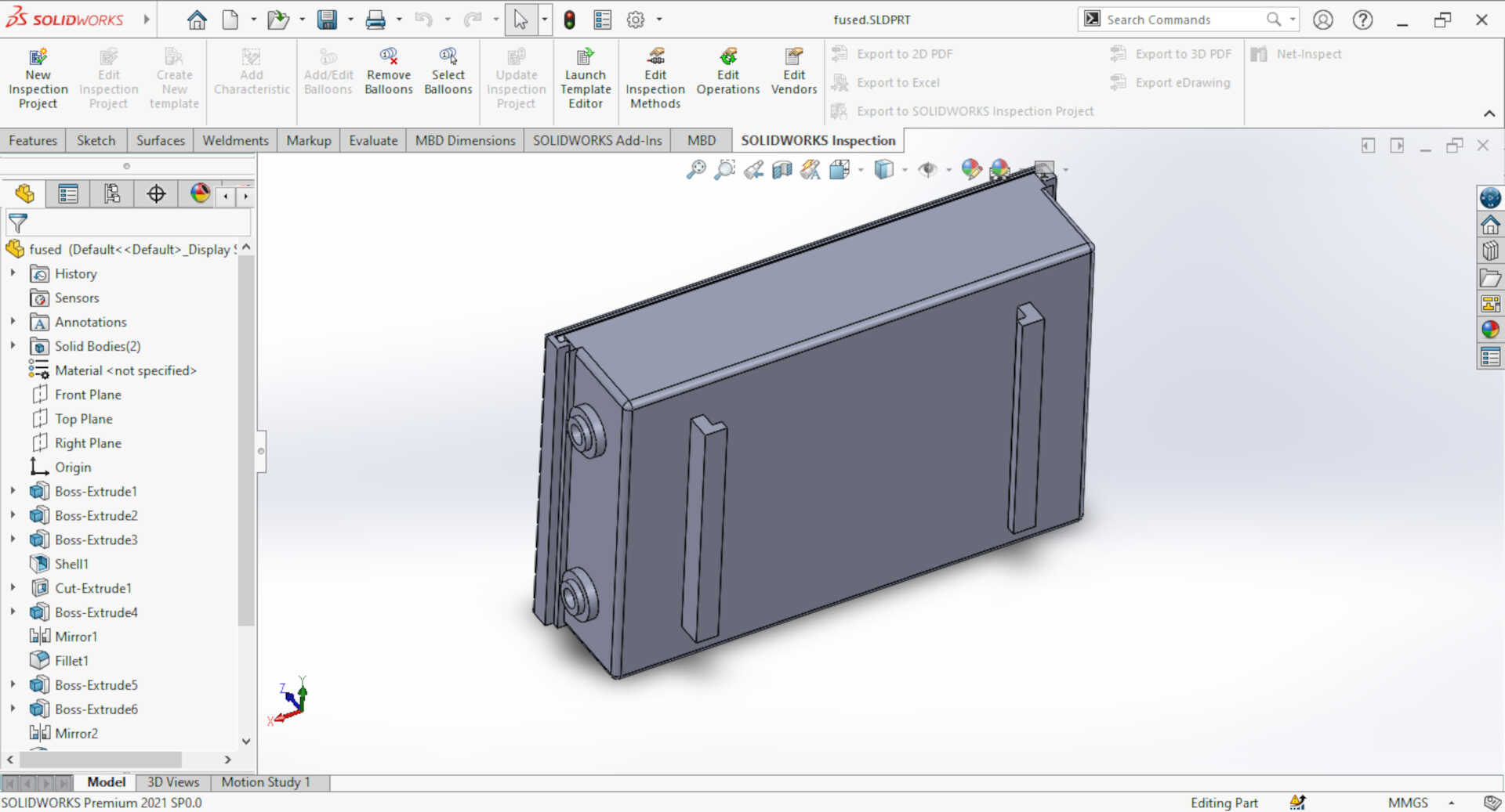 Image: back view showing the mounting rails
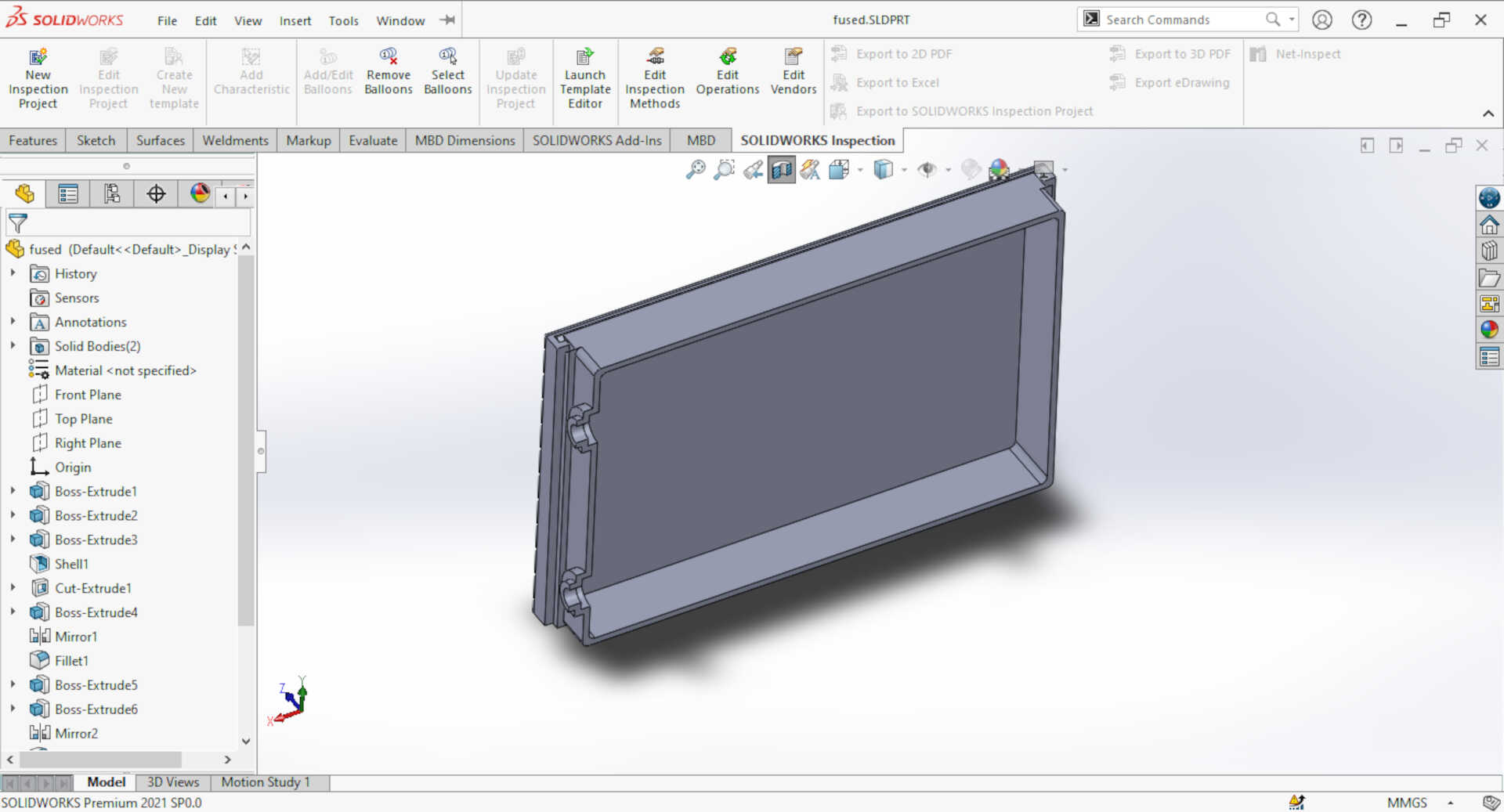 Image: A logitudinal cut showing the hollow inside

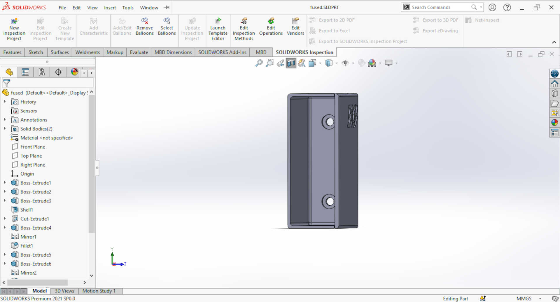 Image: A lateral cut showing the inside.
Slicing
PLA(Polylactic acid) filament was used to print out this component.
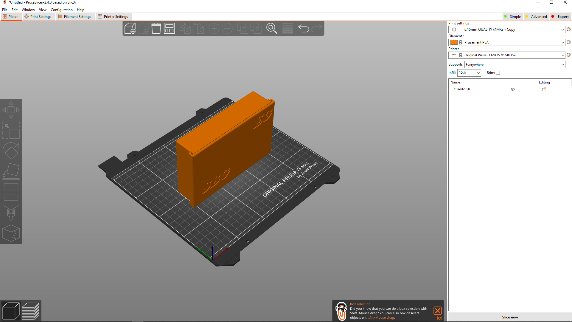 The printer came with its own slicer called PrusaSlicer. The parameters used are below:
-
Layer height: this image below shows the parameters for the layer height used for this print out
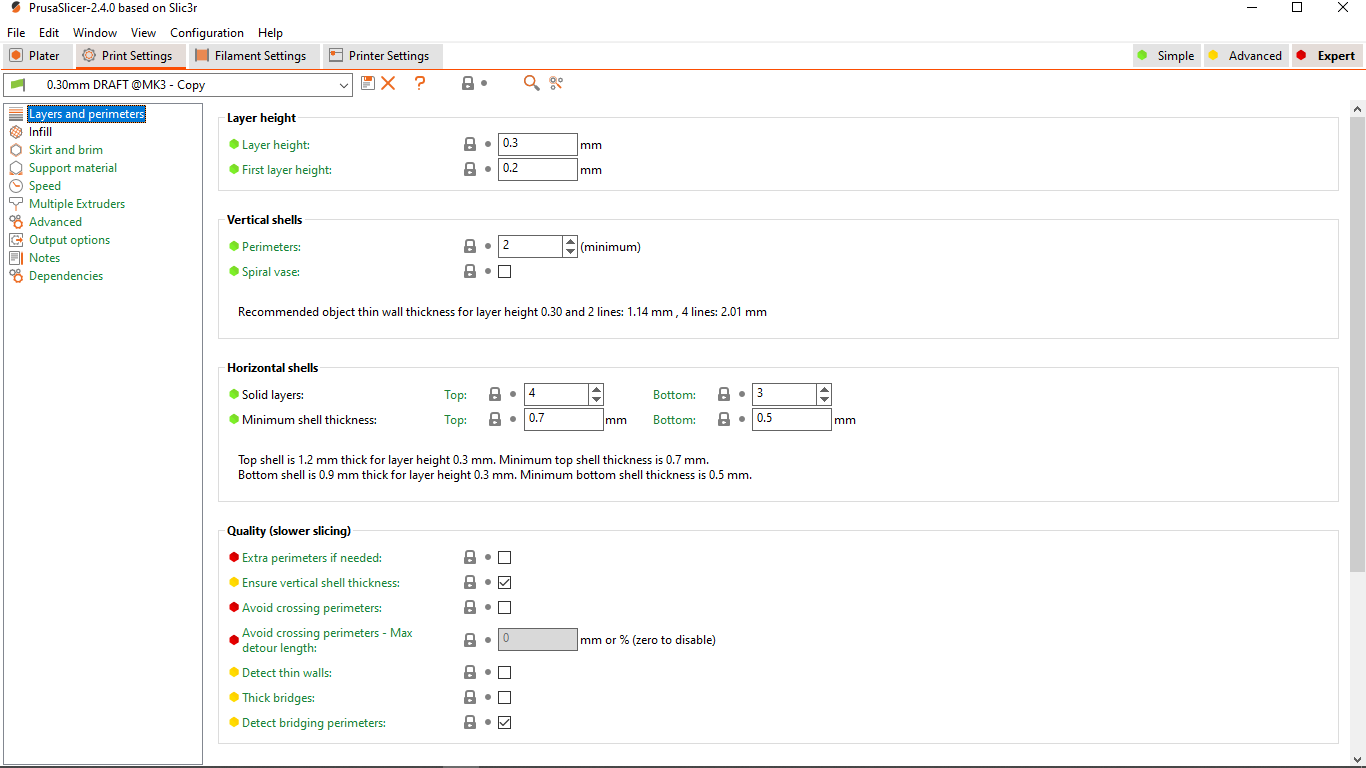
-
Infill: this image below shows the parameters for the amount of infill and the partern used for this print out
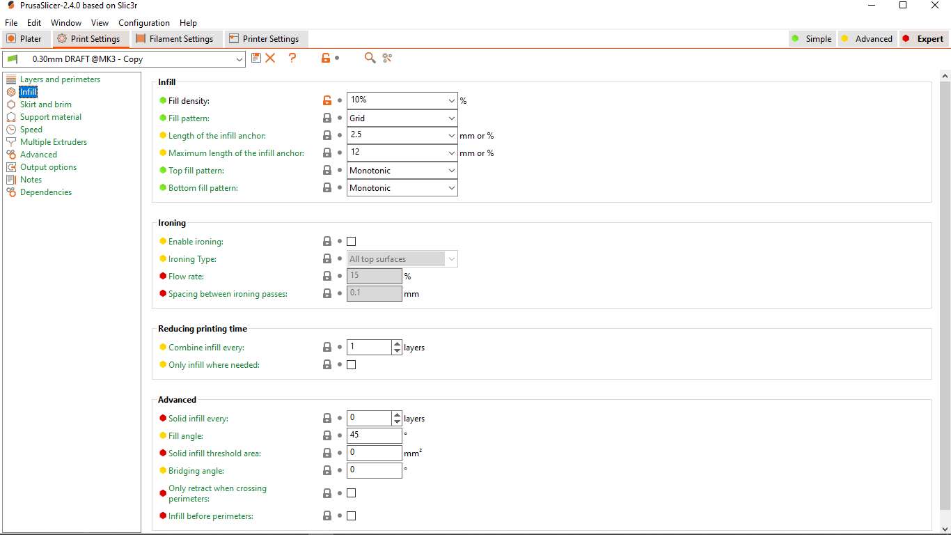
-
Skirt and Brim: this image below shows the parameters for the skirt and brim used for this print out

-
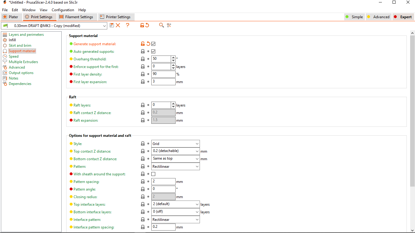
Support: this image below shows the parameters for the support material and the partern used for this print out
The print-outs
It took 10 hours 55 mintues to print it out on the Prusa i3-mk3s using a black PLA filament.
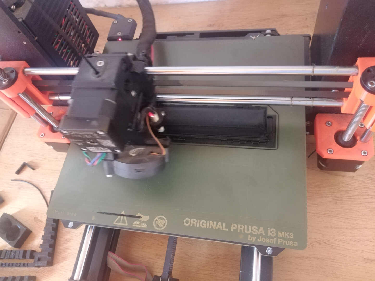 Image: Initial printing process
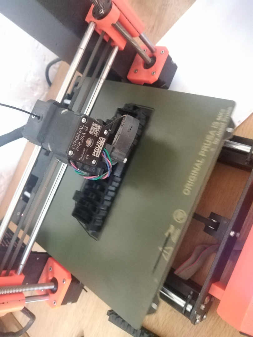 Image: During the printing process
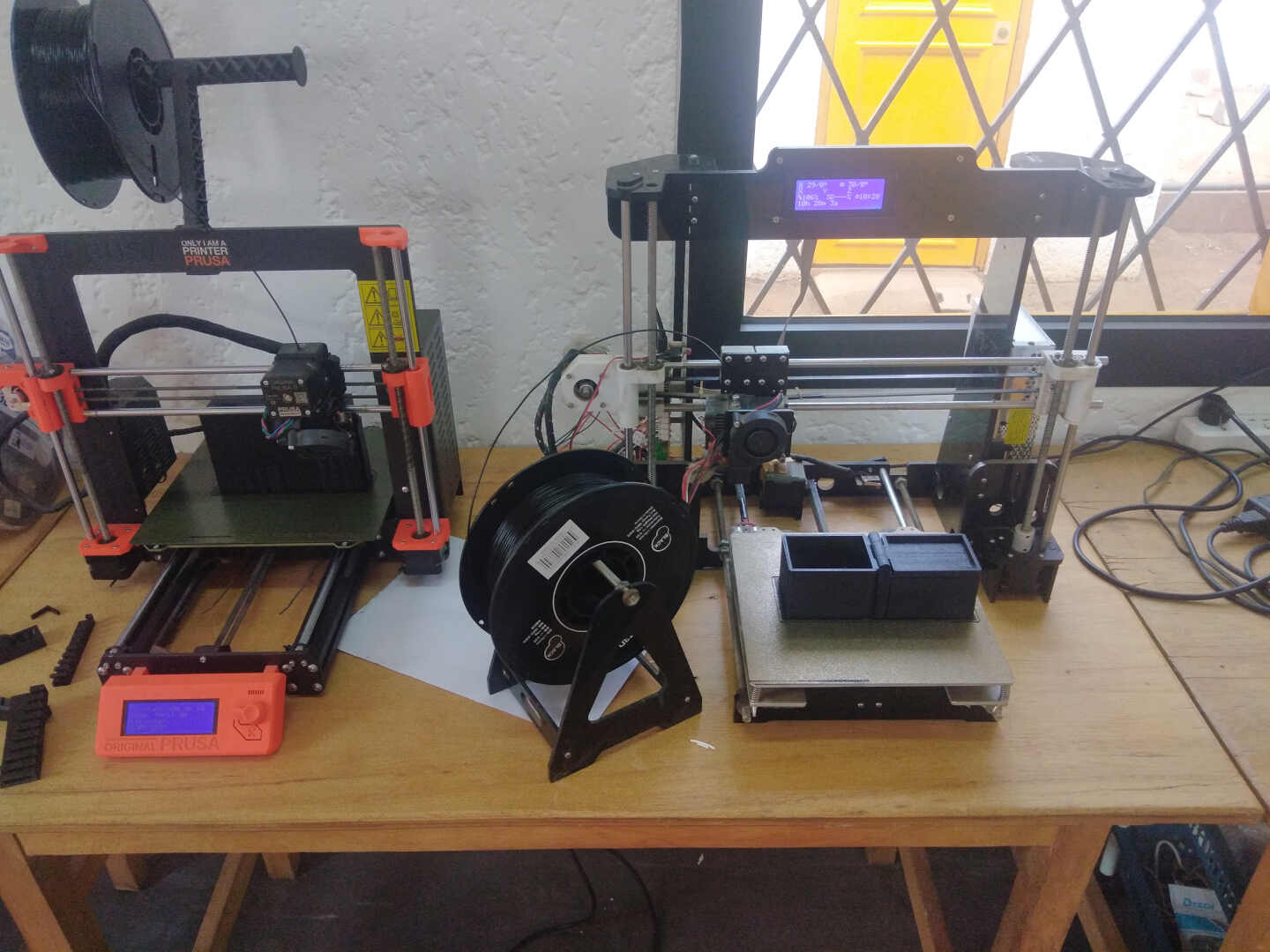 Image: Printing processed finish but it was still on the print bed.
 Image: Removal of the supports in the container
 Image: Removal of the supports on the lid
Image: Finished print out.
Lessons Learnt this week
So with this week’s assignment, I literalily had no errors with my 3D printing assignment but I quite had some issues with the 3D printing.
Runing all the tests on our 3D printer, I have got new knowledge on the dimensions and clearance gaps to use to get good print and to avoid “spagetti” on the prints
I realised I could not 3D scan transparent objects like water bottles, I could not 3D scan objects that had a high glossy finished surface.
files
Electronic_components_1 Electronic_components_2