3. Computer Aided design
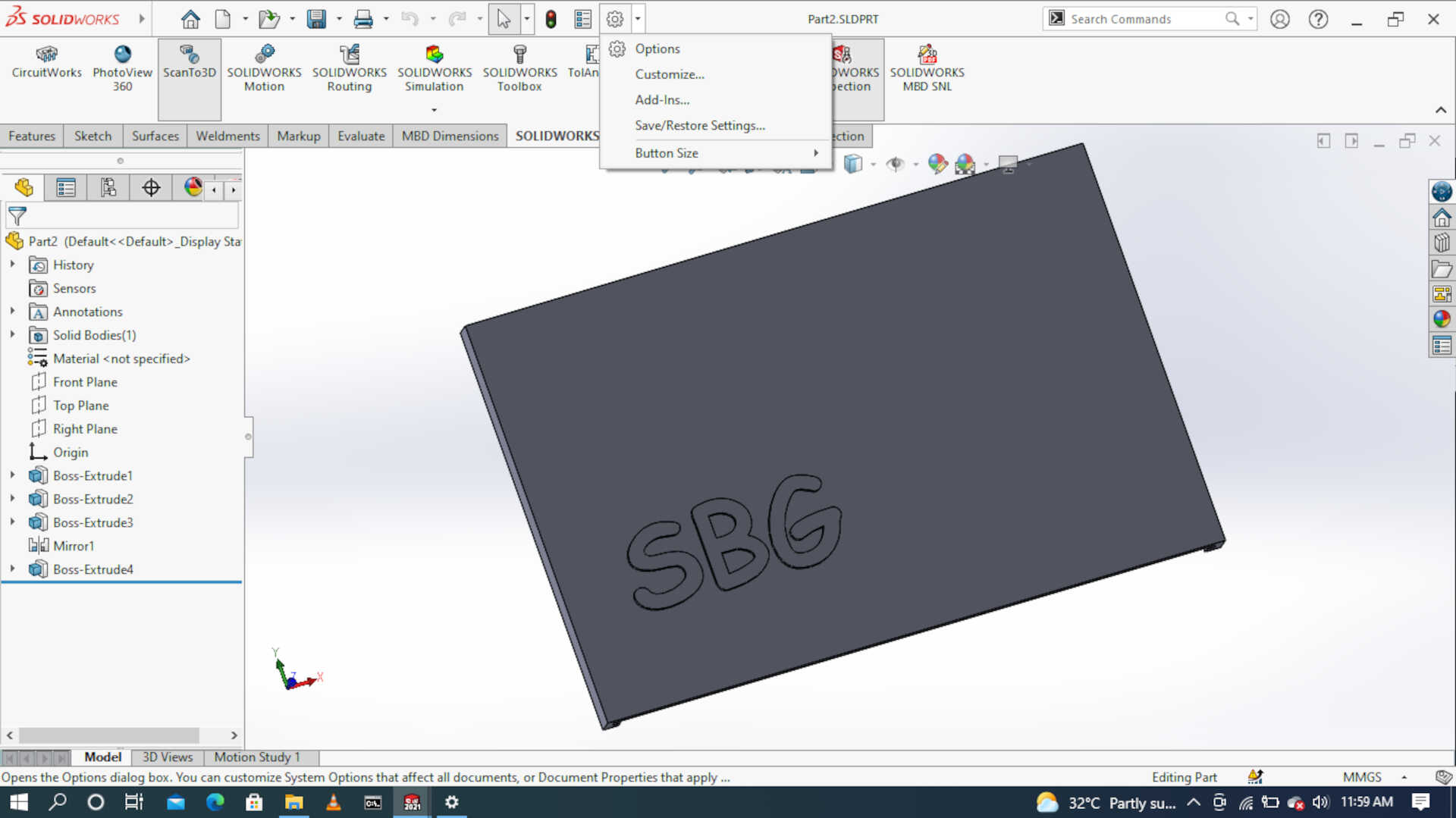
This week I worked on designing and 3D modeling an electronics housing for my final project. The plan is to house the micro-controller board, relays, screen and keypad in one housing component. it will take a rectangular shape with sliding lid to cover it up and it has two holes for the wires to pass through. I will be using BS Dasault SOLIDWORKS for all my 3D modeling related work/assignments.
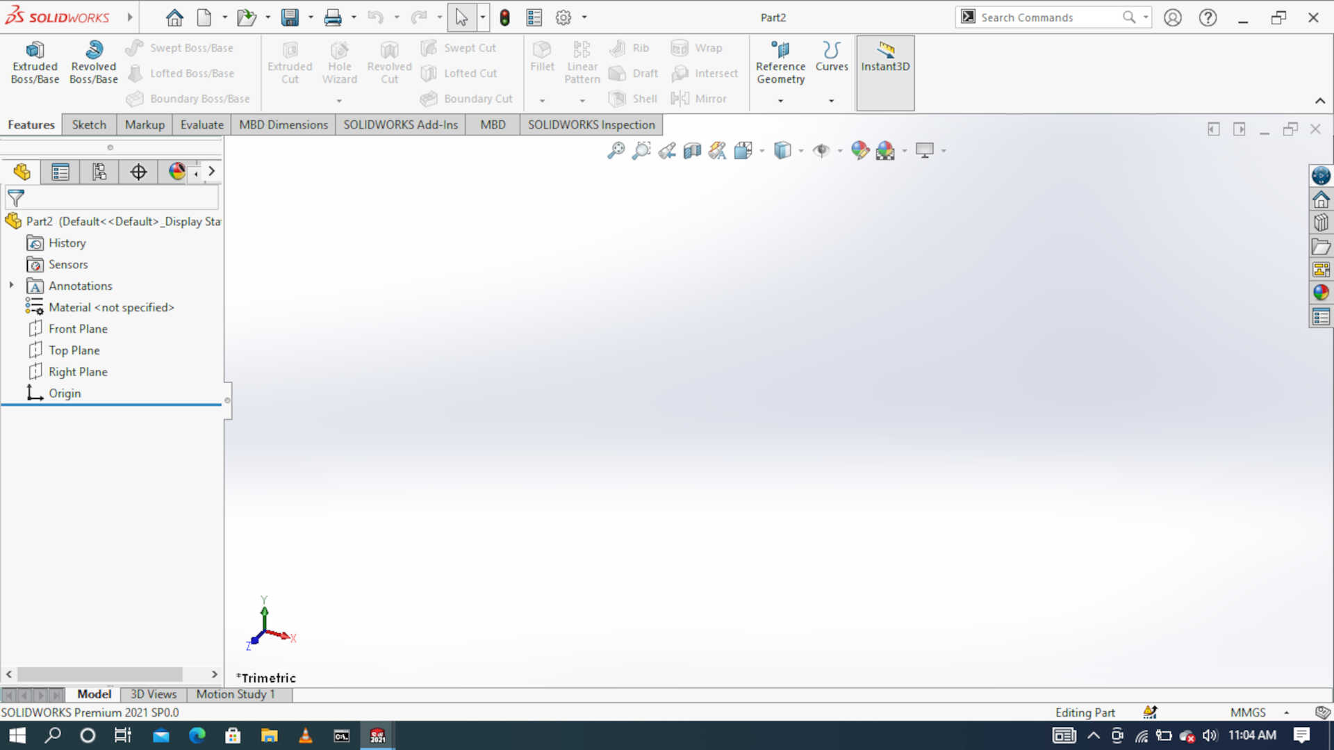 solidworks window.
Raster Vs Vector
In order to design a 2D image, it is very important to know that there are two types of image format:
The raster format (jpg, gif, png…) The vector format (ai, eps, svg…) The main difference between these two formats is that a vector image can be enlarged without losing its quality, whereas a raster image loses its sharpness when enlargedthus it appears blur.
The raster image (or bitmap): It is composed of small points called “pixels” that we do not see with the naked eye. When a raster image is enlarged, this image is no longer visible to the naked eye. When a raster image is enlarged, it becomes blurred because the pixels come out, these are the squares that appear on the screen.
The vector image: It is composed of lines of segments that are linked together by mathematical formulas. It is a system of proportionality and coordinates. Thanks to vectorization, each element has a well-defined place which prevents the image from being distorted.
The image below shows a side-by-side commparison of the two types of images at 1x zoom and at 4x zoom respectively

Using Inkscape
You can get the windows x64 version of the Inkscape software here. The installation is pretty simple and complications-free. So I decided to make a simple 2D model of “NASA” Writing using Inkscape, below you will find screenshots of the installation process and my sketch.
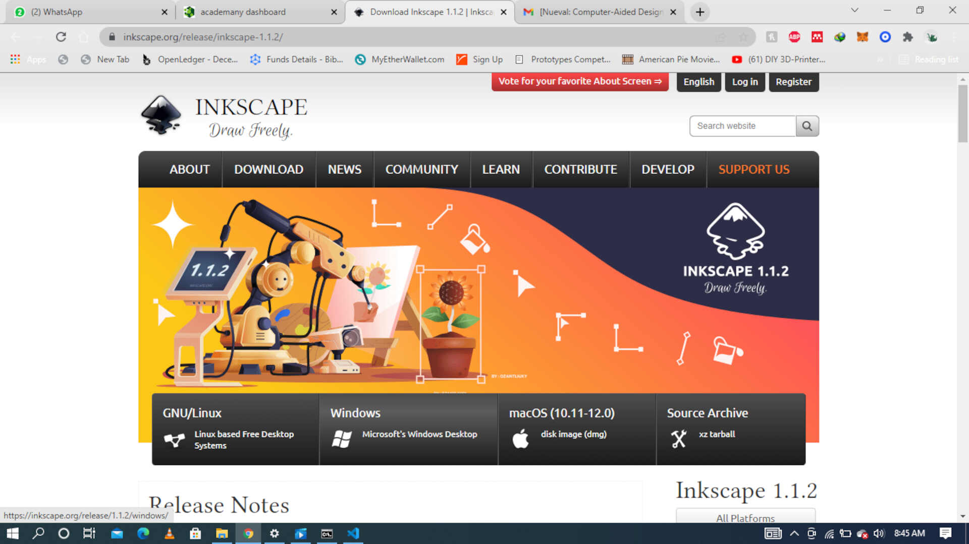 Image: The download page from their official website.
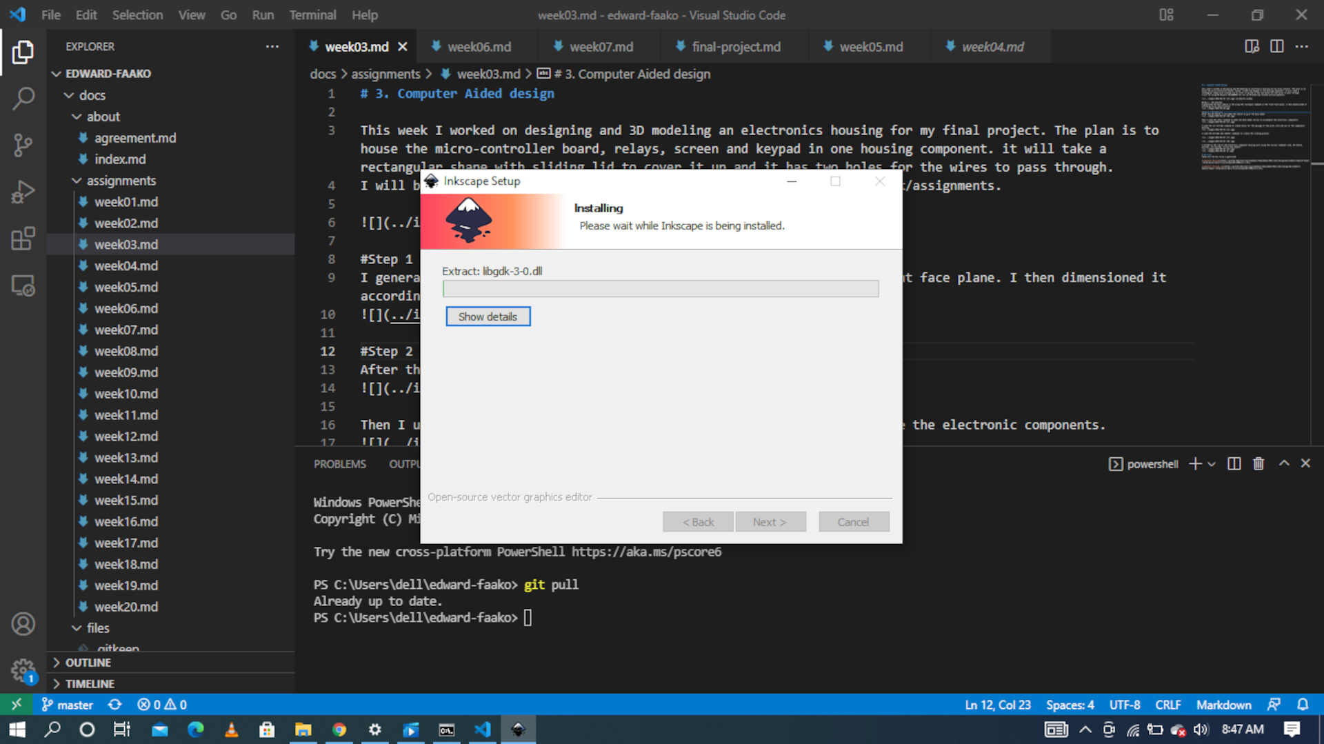 image: screenshot of the installation process
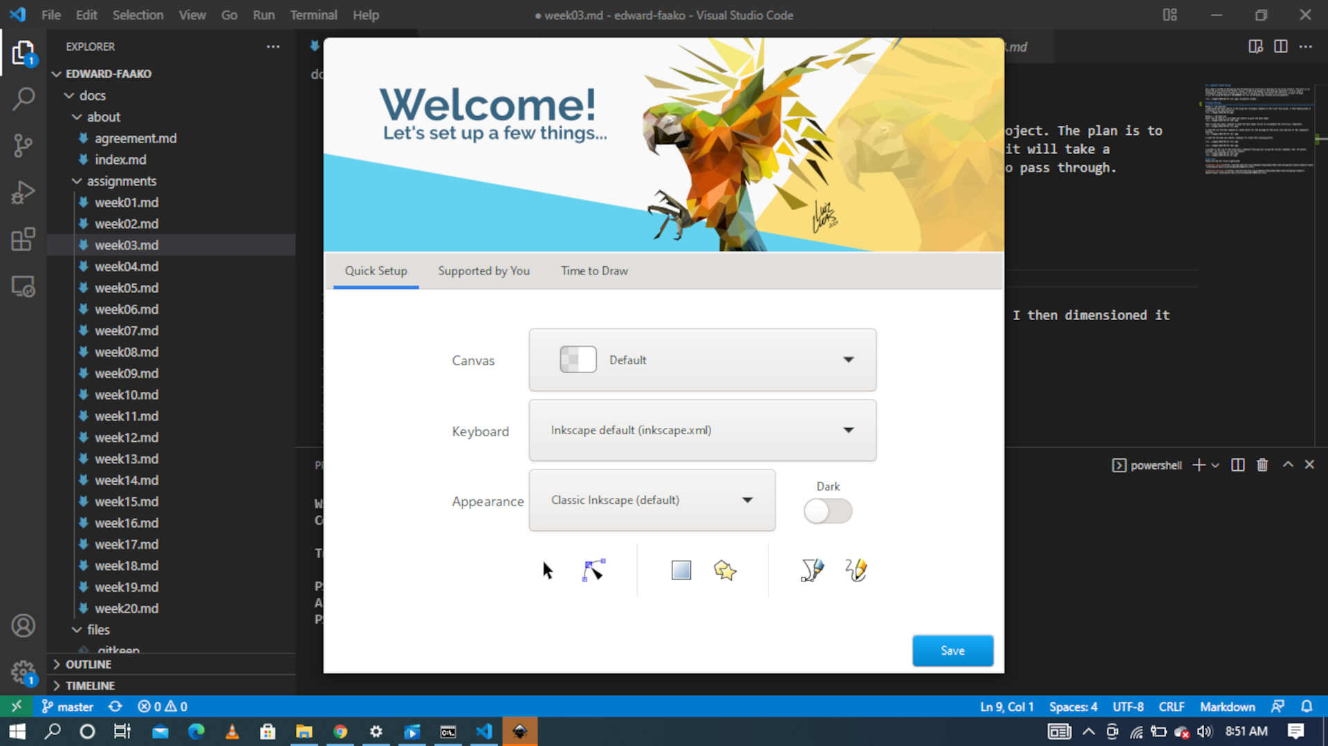 image: the welcome window of Inkscape where you make your preferred settings and choices
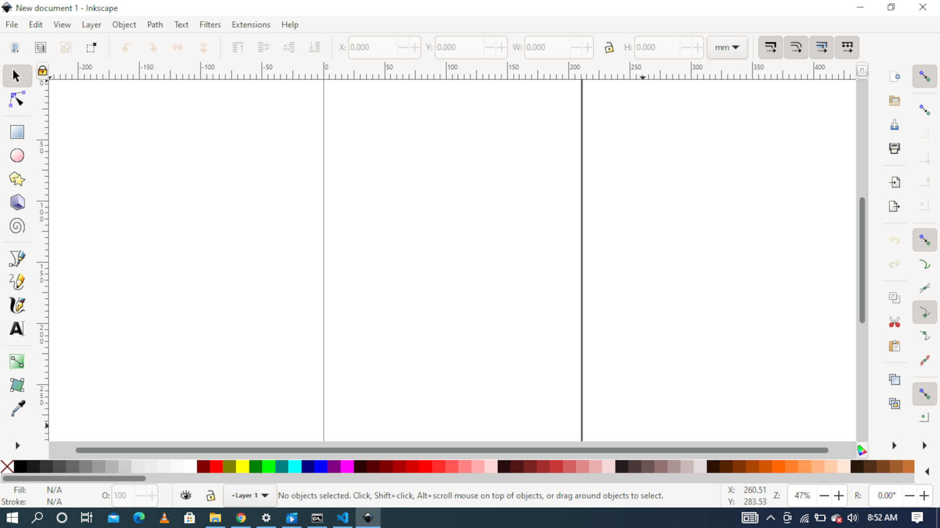 image: the blank drawng space window, this is where are sketches can be made
 imgae: in this picture I used the draw bezier curves and straight line command and the draw free hand line comand to draw this NASA
 image: I used the draw caligraphic or brushes stroke comand to create the deep lines in the NASA drawing.
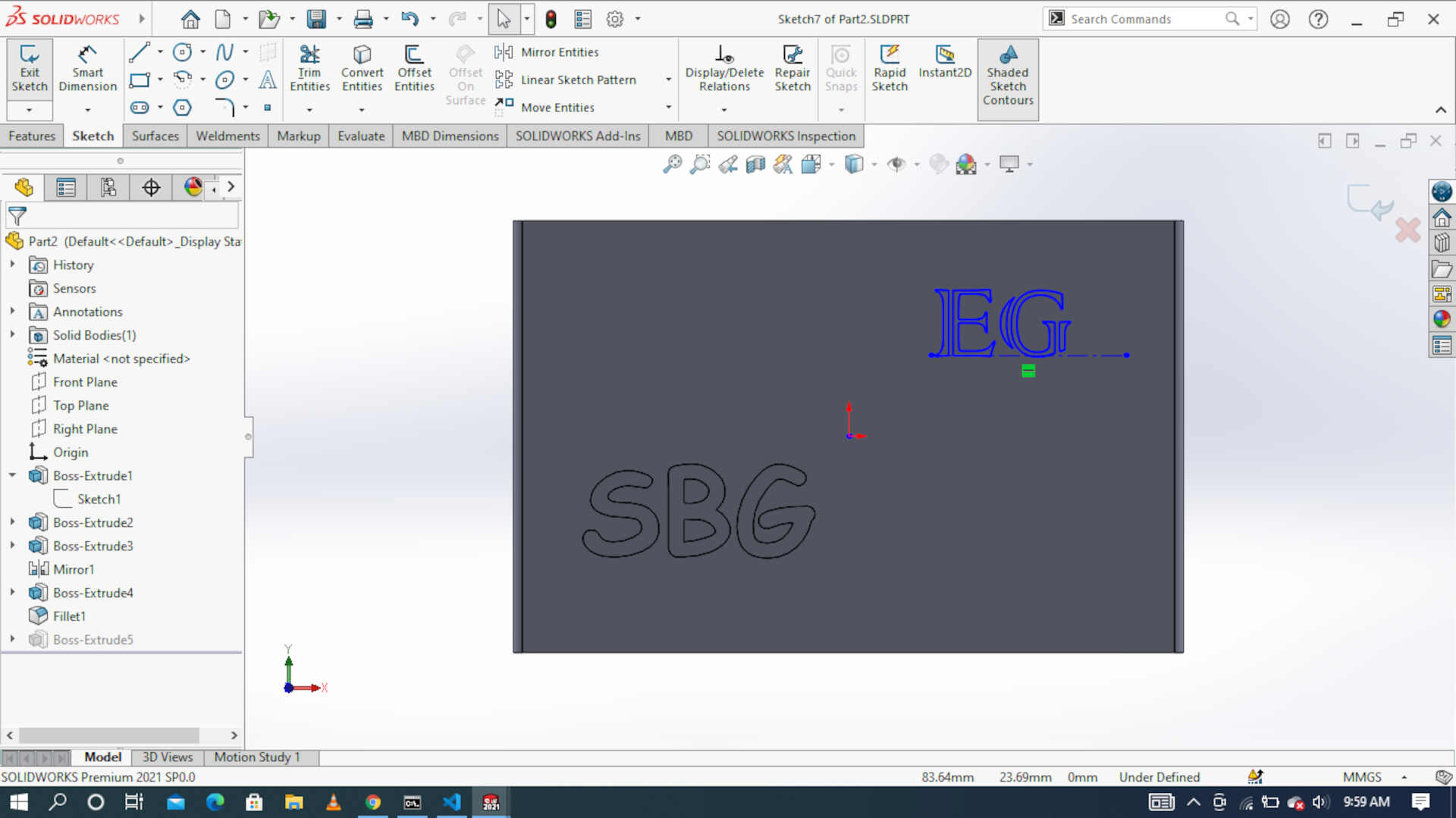
Step 1 - 2D sketches
I generated the base sketch in 2D using the rectangle command on the front face plane. I then dimensioned it according to my specification.

Step 2 - 3D modeling
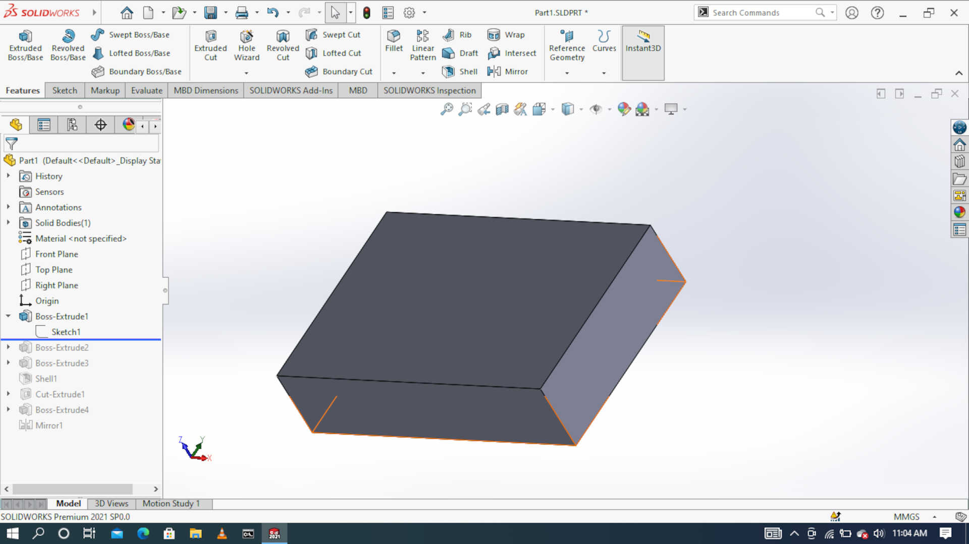
After the 2D sketch, I extruded the sketch to give the base model
Then I used the shell command to make the base model hollow to accomodate the electronic components.
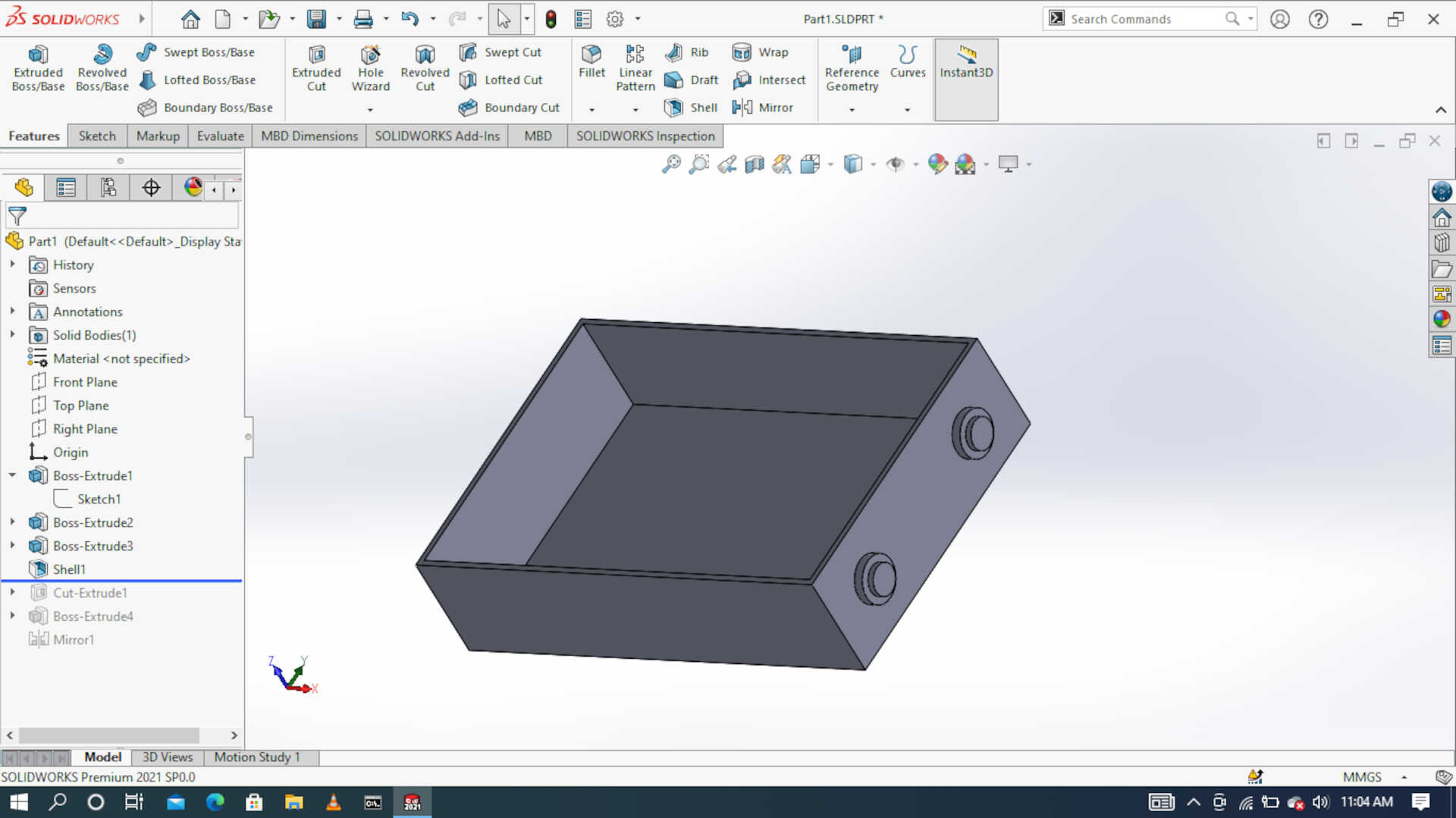
I used the cut estrude command to create holes for the passage of the wires into and out of the components housing.

I used the extrude and chamfer commands to create the sliding grooves.
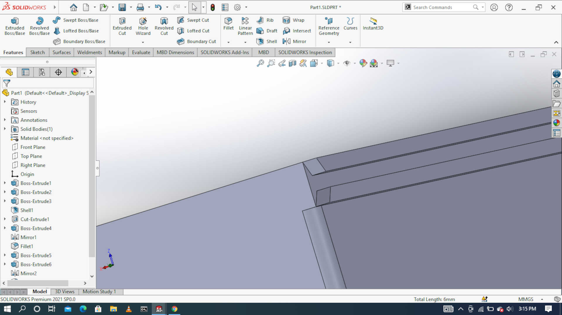

I worked on the lid of the electronic component housing unit using the various commands like, 2D sketch,extrude, cut extrude, fillet and chamfer.
3D files
These are the STL files I generated
Now, I use Gimp 2.10 batch image manupulator software to compress and resize my images before I upload them on to my GitLab server

 image: resizing
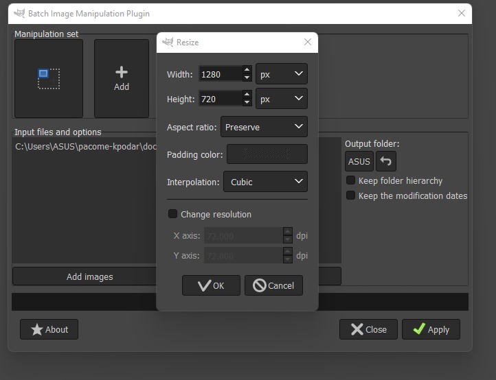 image: resizing
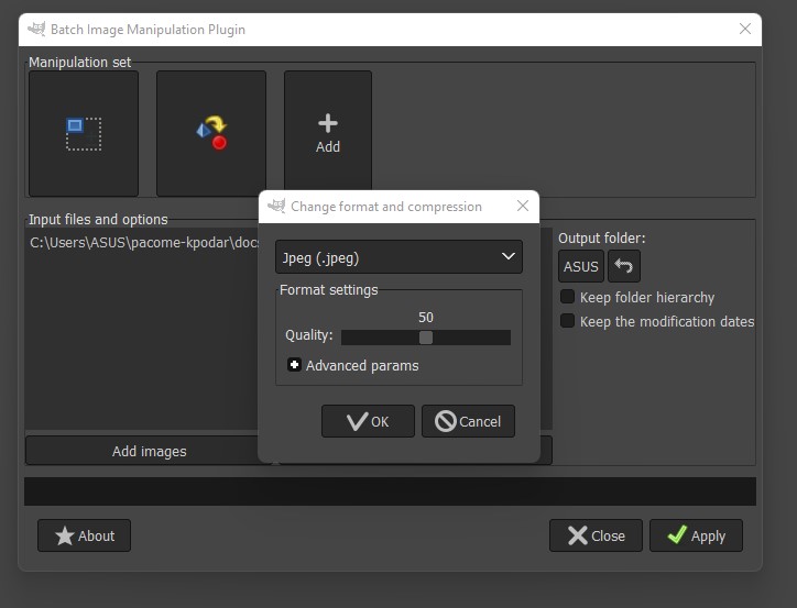 image: compression and format of the picture
After compressing the images I copy the necessary ones into my local folder and then Git push them when I am submitting the assignment.