20. Project development

THE IDEA
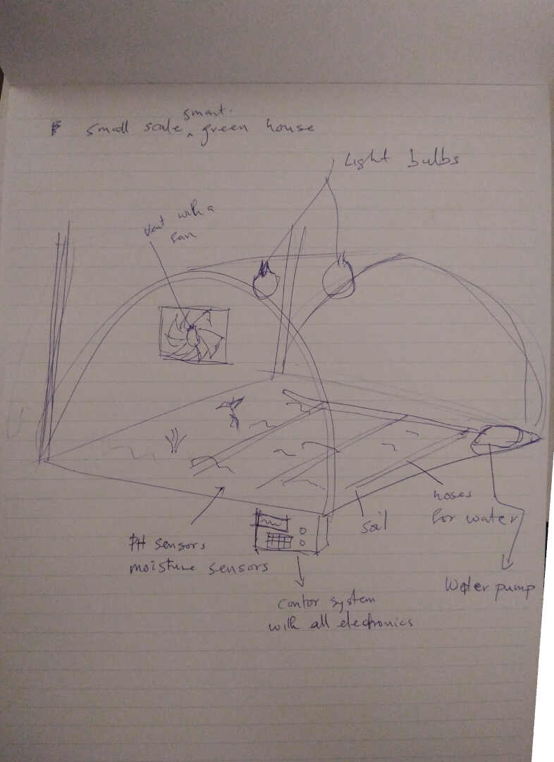
This idea came when I stayed in a big city for some months. the thought of a smart greenhouse for urban settlers. So this is basically a greenhouse that is going to be controlled using a microcontroller, some sensors, light bulbs, water pump and a ventilation fan to cool down the greenhouse. These will measure and collect the data from the various sensors like the temperature sensors, moisture sensors, photo sensors. Which will then be used to produce the necessary weather conditions for healty plant growth.
Working Principles
- Measures and records the soil moisture
- measures and records the ambient temperature and humidity in the enclosure
- measures the light intensity of the surrounding
- cools down the enclosure with the use of a 12V fan that uses the temperature & humidity recorded
- waters the soil beds with the use of a 12V water pump using the data from the recorded soil moisture
- ligthens up the enclosure with 12V LEDs using the light intensity recorded
- displays necessary information on a 16x2 LCD screen for the user.
PROJECT PLANNING
PROJECT PHASES The project will be divided into the following phases:
- The Design
- The Production
- The Programing
- The Assembly
- The final Result
THE SKILLS USED
In order to finish my final project, several skills learned during the last 19 Weeks in FabAcademy have been used:
- 2D/3D design
- Laser cutting
- 3D Printing
- CNC Milling
- Electronic Design
- Electronic Production
- Programing
- Network and communication
1. THE DESIGN
Electronics system
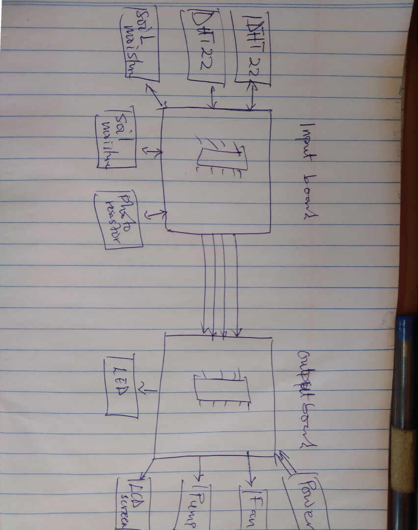
There will be two boards making use of the networking and communication principles, the input board and the output board. These two boards will communicate using the I2C bus connection. The input board will have the input sensors connected and send the data read to the out put board to execute the camands using the devices connected to it.
Electronic Board case
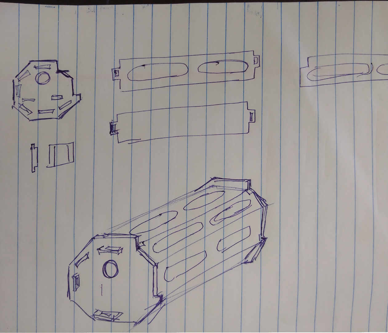
The Enclosure 2D
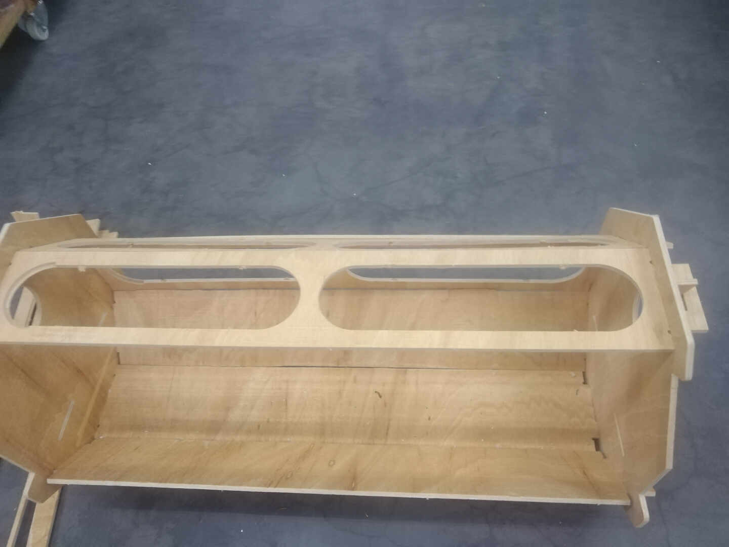
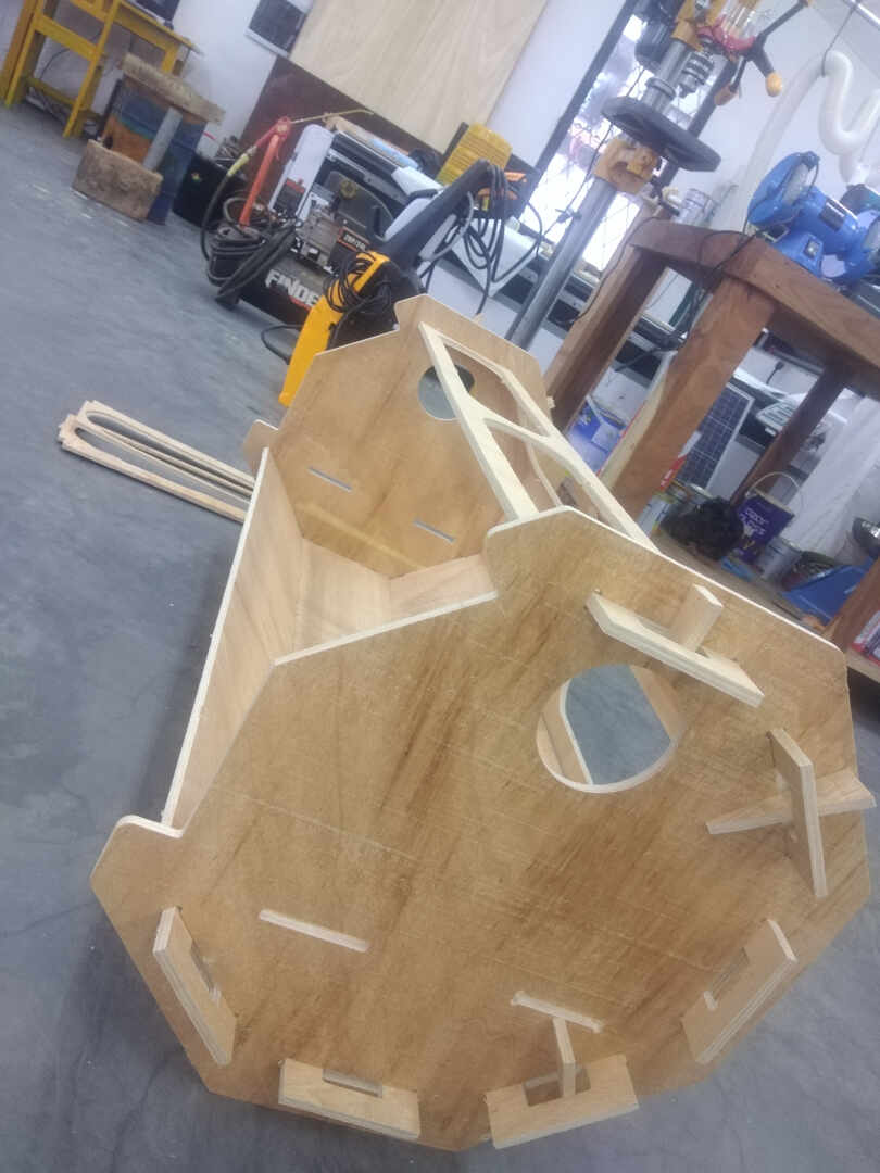
The enclosure is designed to have and octagon cross-section with cut outs to allow sun light reach the plants.
2. THE PRODUCTION
Electronic Board case
3D printing will be used for the production of this component. You can refer to Week 03 for the design process and Week 06 for details on the 3D printing


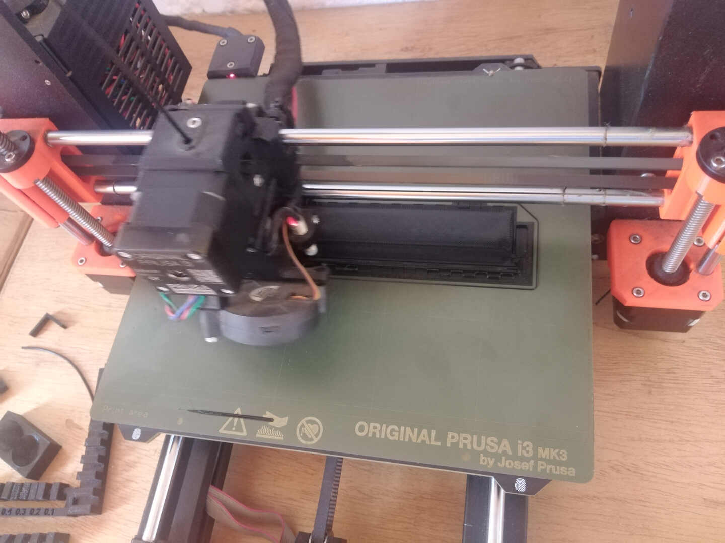 Image: Initial printing process
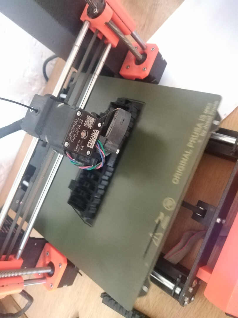 Image: During the printing process
 Image: Removal of the supports in the container
 Image: Removal of the supports on the lid
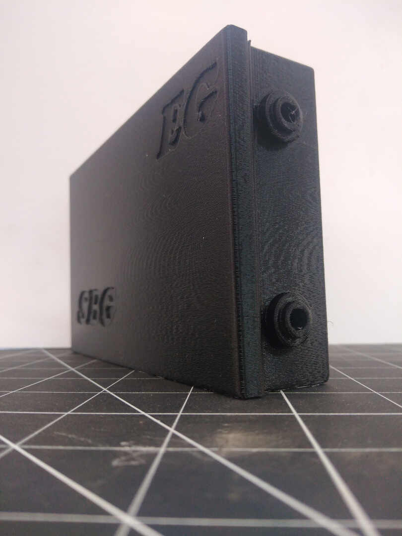
 Image: Finished print out.

Input Board
As stated, there are two boards to make this system a sucess and this the production of the input board. It was designed using KiCAD 6.
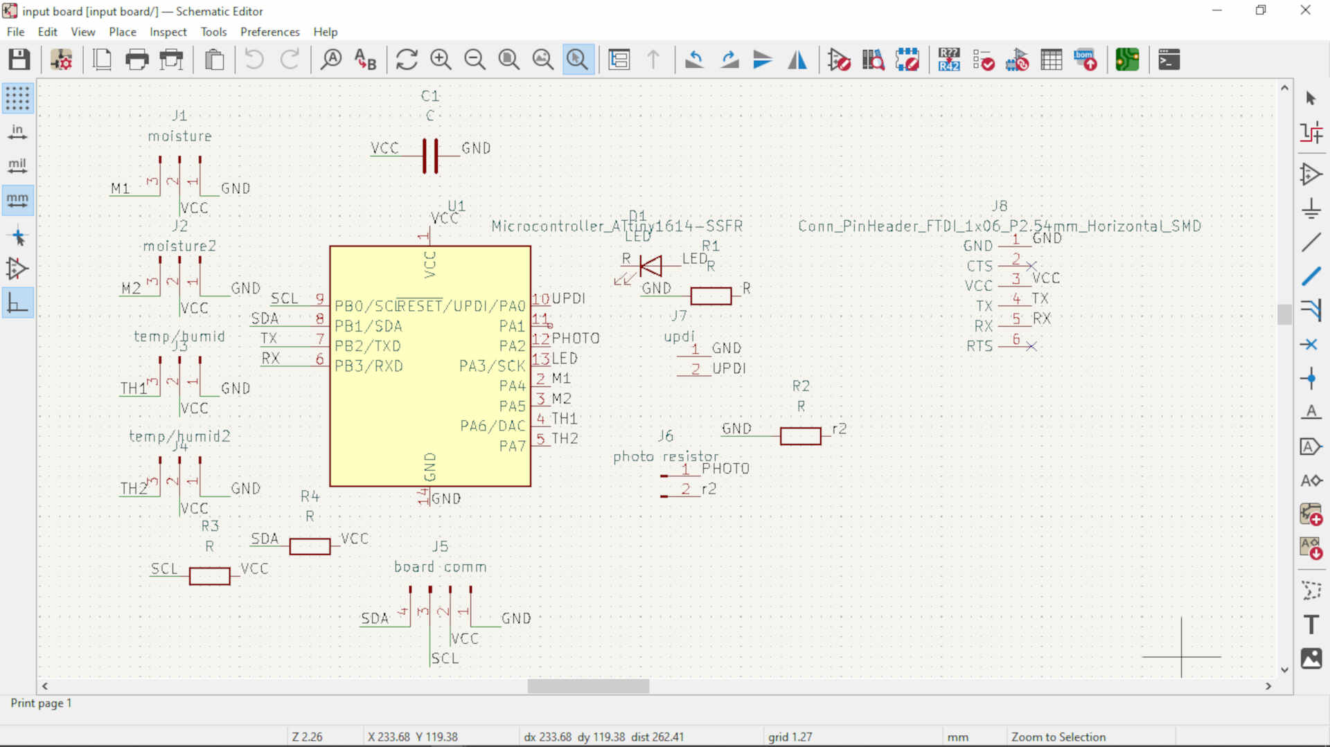 image: this is the schematic design of the input board
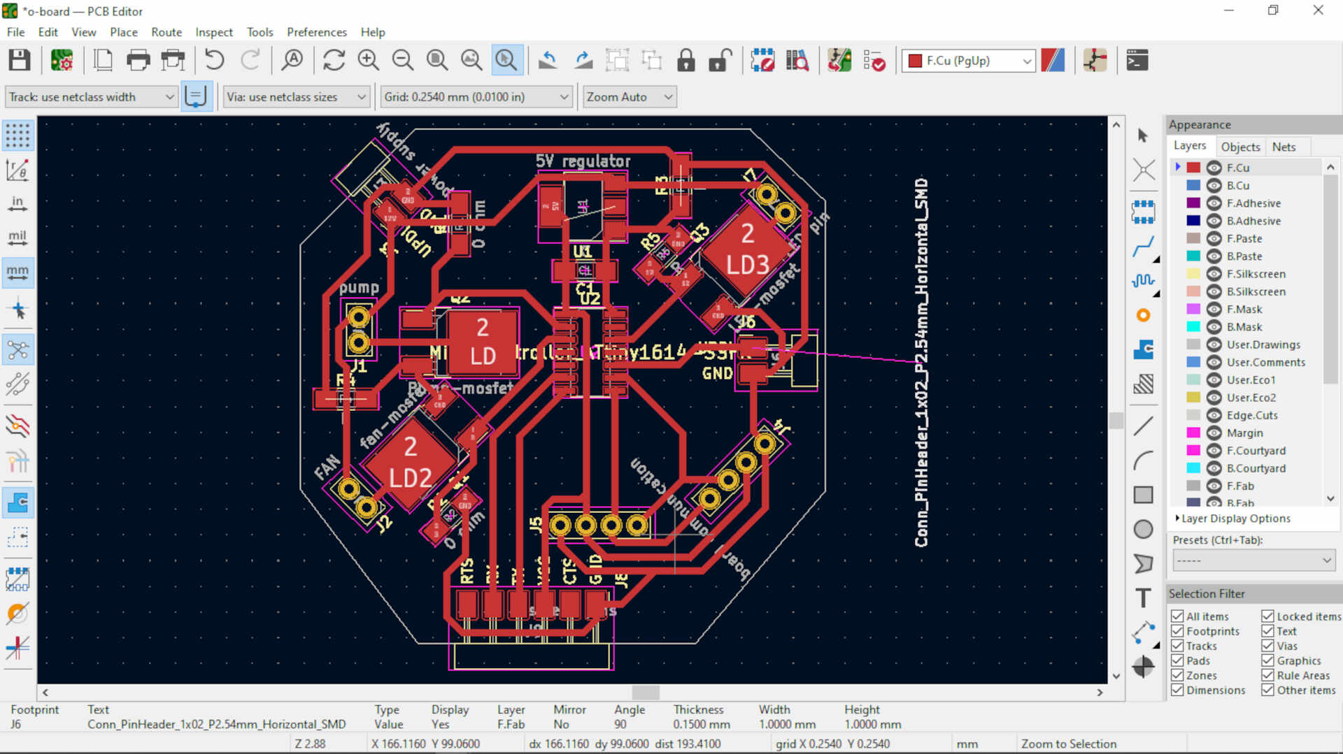
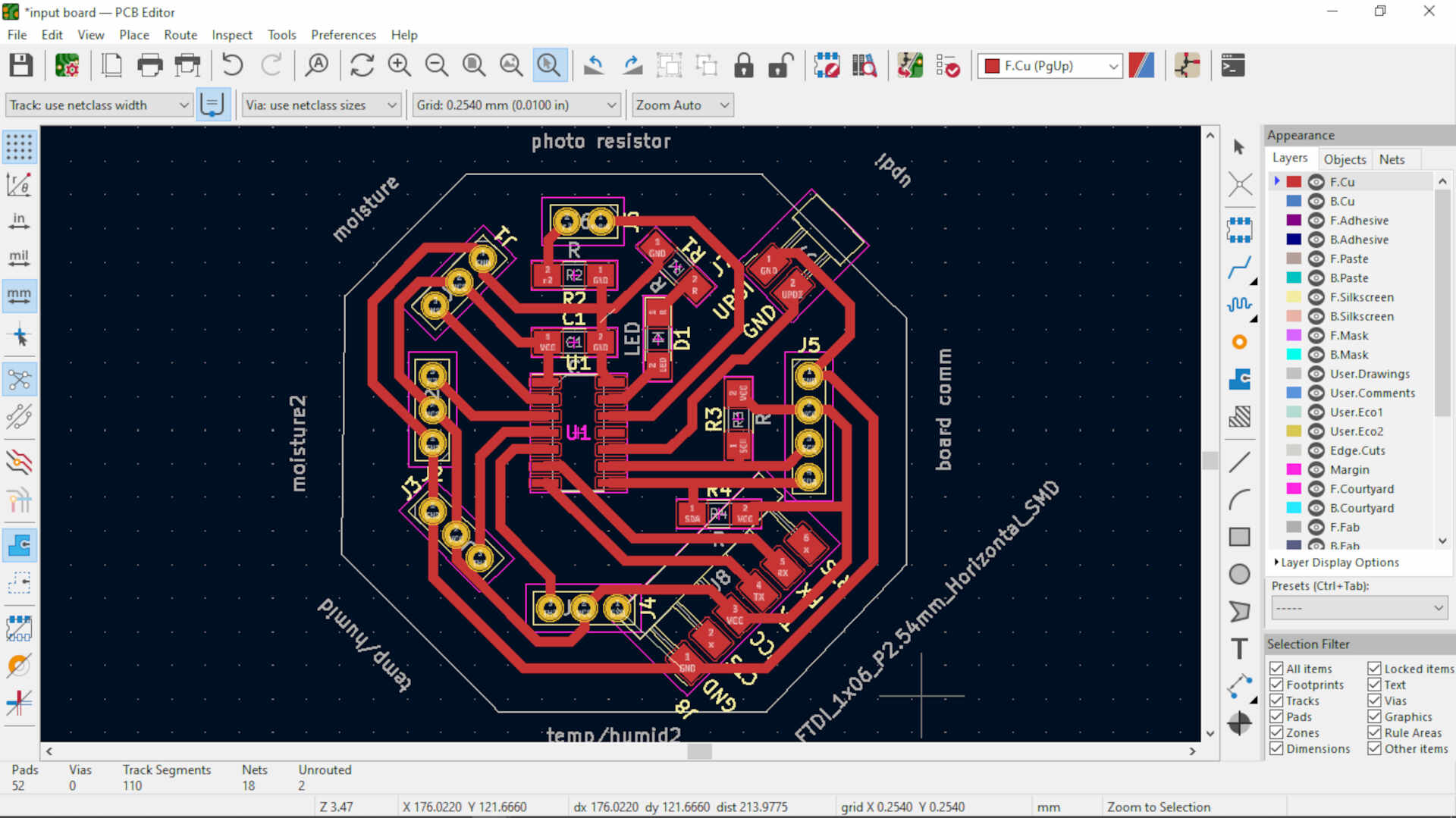 image: the PCB(trace layout) of the input board
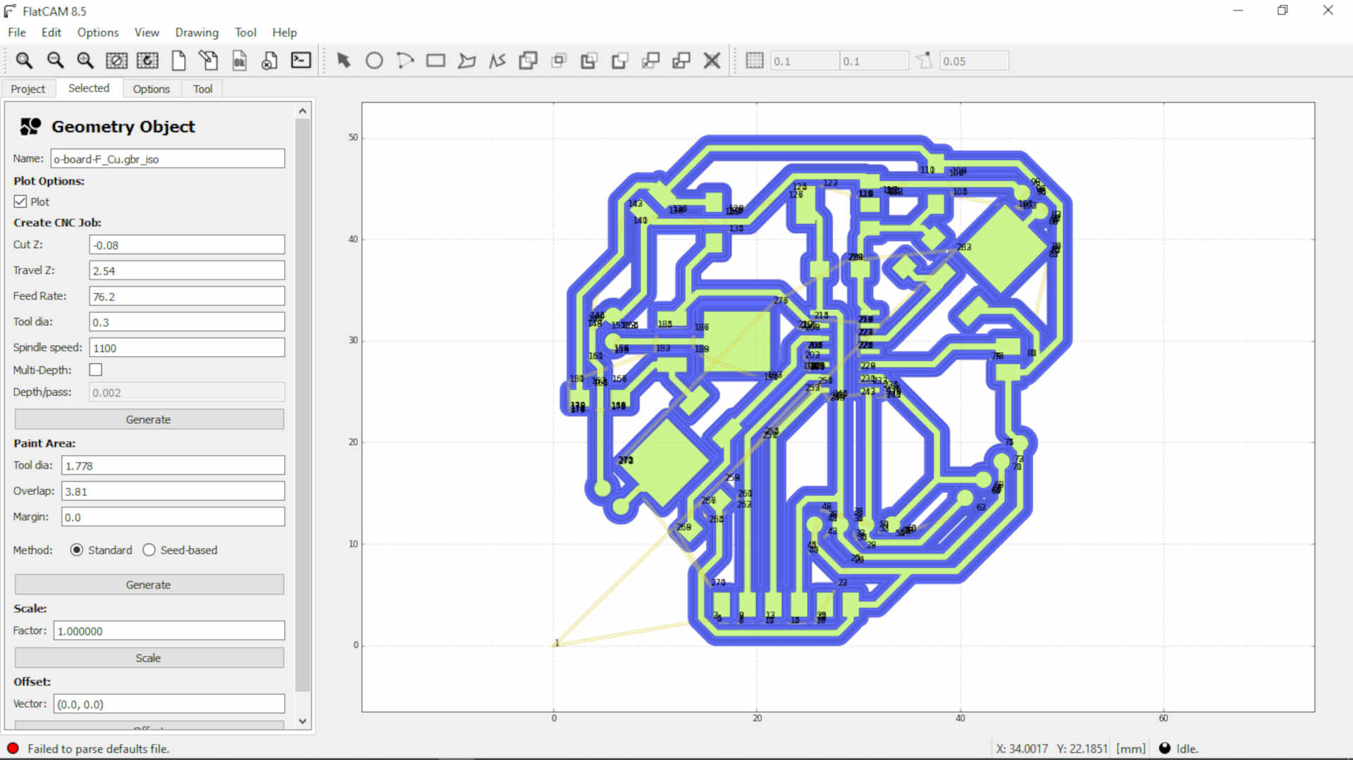
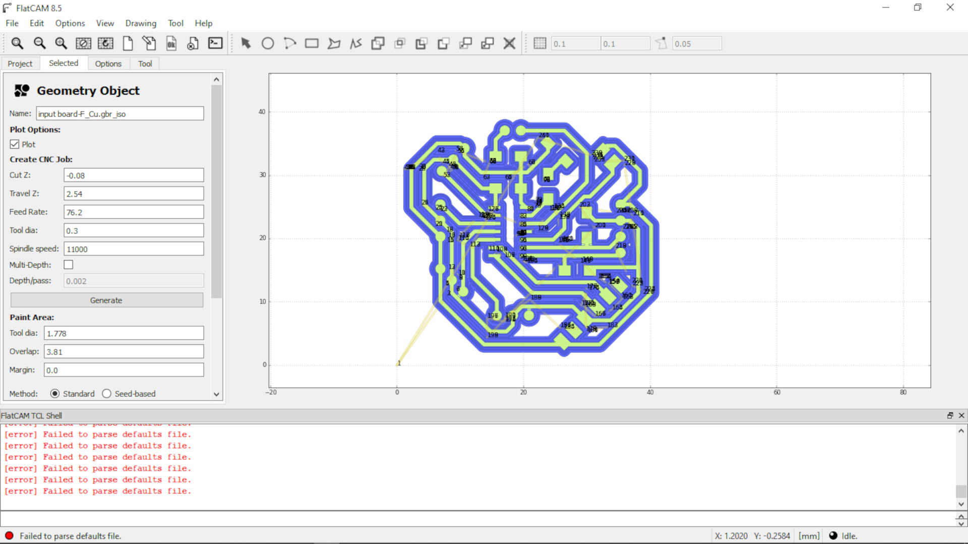 image: generating the Gcode for the copper traces to be milled
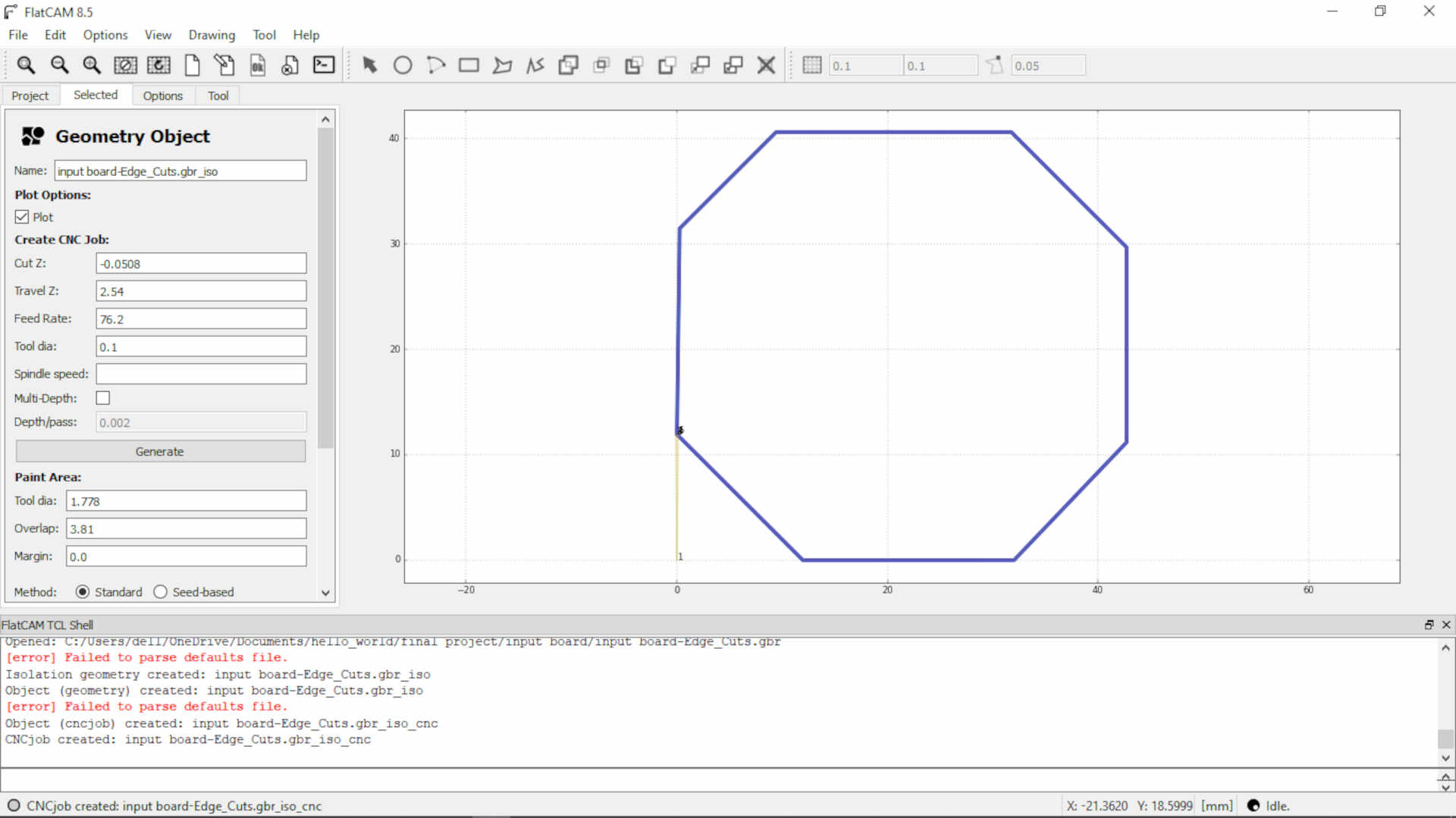 image: generating the Gcode for the edge cuts
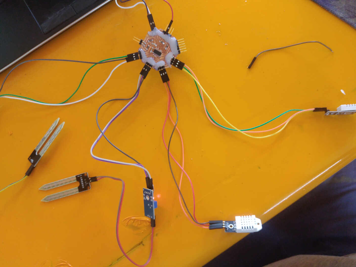 image: this is the input board with the sensors hooked up to it.
Output board


 me soldering the components to the various boards
 finished assembly of the boards and components
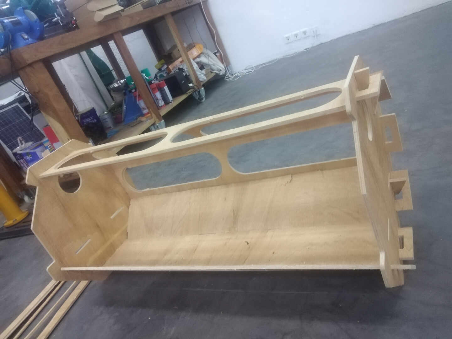
Enclosure
The enclosure will be manufactured/produced using the skills learned during the CNC machining week. You can refer to week 08 to see in full detail of the machining process.
3. THE PROGRAMMING
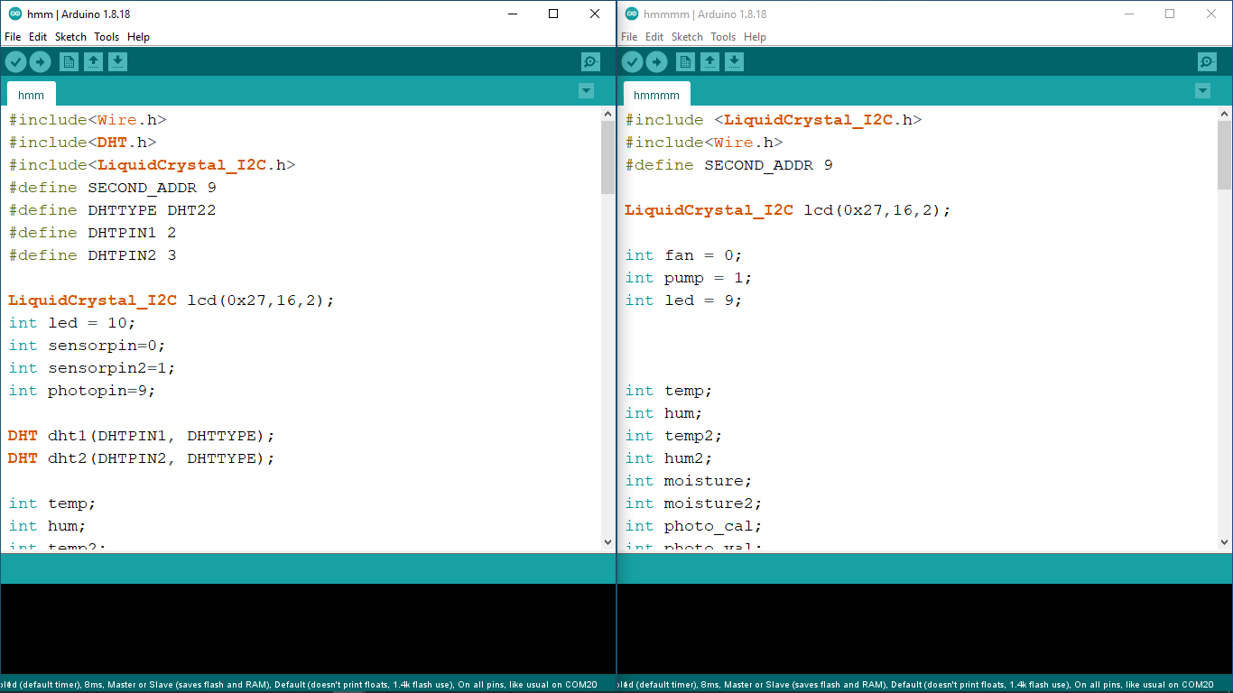
now , having two separate boards means that I will have to write two programs for each board to function as desired. The input board* is set as the controller to send data sets to the output board* to execute the actions. skills from : - Week 11 - Week 12 - Week 14
The Arduino IDE was used to write the programes and upload them to the individual boards.
some modifications were made to the set of codes in the Week 14 to acheive the final codes for the project.
The *Master code for the Input board.
#include<Wire.h>
#include<DHT.h>
#include<LiquidCrystal_I2C.h>
#define SECOND_ADDR 9
#define DHTTYPE DHT22
#define DHTPIN1 2
#define DHTPIN2 3

LiquidCrystal_I2C lcd(0x27,16,2);
int led = 10;
int sensorpin=0;
int sensorpin2=1;
int photopin=9;

DHT dht1(DHTPIN1, DHTTYPE);
DHT dht2(DHTPIN2, DHTTYPE);

int temp;
int hum;
int temp2;
int hum2;
int photo_cal;
int photo_val;
int moisture;
int moisture2;


void setup() {
  // put your setup code here, to run once:
dht1.begin();
dht2.begin();
Wire.begin();
pinMode(led, OUTPUT);
photo_cal = analogRead(photopin);
//photo_cal = random(0, 100);
lcd.init();
 lcd.backlight();
lcd.clear();
lcd.setCursor(0,0);
lcd.print(" Smart Backyard ");
lcd.setCursor(3,1);
lcd.print(" Garden");
delay(5000);
Serial.begin(9600);

}

void loop() {
 // put your main code here, to run repeatedly:
temp = dht1.readTemperature();
hum  = dht1.readHumidity();
temp2 = dht2.readTemperature();
hum2 = dht2.readHumidity();

moisture = 1023 - analogRead(sensorpin);
moisture = map(moisture,7,910,0,100);
moisture2 = 1023 - analogRead(sensorpin2);
moisture2 = map(moisture2,7,910,0,100);

photo_val = analogRead(photopin);
//photo_val = random(0, 100);

digitalWrite(led,HIGH);

Serial.println("temp & Humidity: ");
Serial.println(temp);
Serial.println(hum);
Serial.println("temp2 & Humidity2: ");
Serial.println(temp2);
Serial.println(hum2);
Serial.print("mositure: ");
Serial.println(moisture);
Serial.print("mositure2: ");
Serial.println(moisture2);

lcd.setCursor(0,0);
lcd.print("Temp&hum:");
lcd.print(temp);
lcd.print("C ");
lcd.print(hum);
lcd.print("%");
lcd.setCursor(0,1);
lcd.print("moisture %: ");
lcd.print(moisture);
lcd.print("%");

if (photo_val<photo_cal-50)
{
  digitalWrite(led,HIGH);
  Serial.println("Led On");
  }
  else
{
  digitalWrite(led,LOW);
  Serial.println("Led Off");
  }

Wire.beginTransmission(SECOND_ADDR);
Wire.write(temp);
Wire.write(hum);
Wire.write(temp2);
Wire.write(hum2);
Wire.write(moisture);
Wire.write(moisture2);
Wire.write(photo_cal);
Wire.write(photo_val);
 Wire.endTransmission();
delay(2000);
}
The code above controls the input board, it reads and records data from the sensors and then sends these data sets to the slave board using the I2C protocols.
The *Slave board for the Output Board.
#include <LiquidCrystal_I2C.h>
#include<Wire.h>
#define SECOND_ADDR 9

LiquidCrystal_I2C lcd(0x27,16,2);

int fan = 0;
int pump = 1;
int led = 9;


int temp;
int hum;
int temp2;
int hum2;
int moisture;
int moisture2;
int photo_cal;
int photo_val;


void setup() {
  // put your setup code here, to run once:
  pinMode(fan, OUTPUT);
  pinMode(pump, OUTPUT);
  pinMode(led, OUTPUT);
Wire.begin(SECOND_ADDR);
Wire.onReceive(receiveEvent);
Serial.begin(9600);
/**lcd.init();
 lcd.backlight();
lcd.clear();
lcd.setCursor(0,0);
lcd.print(" Smart Backyard ");
lcd.setCursor(3,1);
lcd.print(" Garden");
delay(5000);
lcd.clear();**/
}
void receiveEvent()
{

  temp=Wire.read();
  hum=Wire.read();
   temp2=Wire.read();
  hum2=Wire.read();
  moisture=Wire.read();
 moisture2=Wire.read();
 photo_cal=Wire.read();
 photo_val=Wire.read();
}
void loop()
{
  // put your main code here, to run repeatedly:
//lcd.clear();


Serial.print("| Temp = ");
Serial.print(temp);
Serial.print("| Humidity = ");
Serial.print(hum);
Serial.print("|Mositure1 = ");
Serial.print(moisture);
Serial.print("|Mositure2 = ");
Serial.print(moisture2);
Serial.print(" | Photo cal = ");
Serial.print(photo_cal);
Serial.print(" | Photo val = ");
Serial.println(photo_val);


// for the fan control
if (temp>=35)
{
  digitalWrite(fan,HIGH);
  Serial.println("Fan ON");
  }

 else
 {
  digitalWrite(fan,LOW);
  Serial.println("Fan Off");
  }

// pump control

if (moisture<=40)
{
  digitalWrite(pump,HIGH);
  Serial.println("Pump ON");

  }

else
{
  digitalWrite(pump,LOW);
  Serial.println("Pump Off");
  }

// led control

if (photo_val<photo_cal-50)
{
  digitalWrite(led,HIGH);
  Serial.println("Led On");
  }
  else
{
  digitalWrite(led,LOW);
  Serial.println("Led Off");
  }

delay(2000);
}
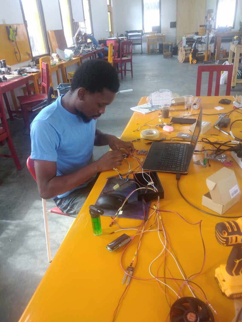
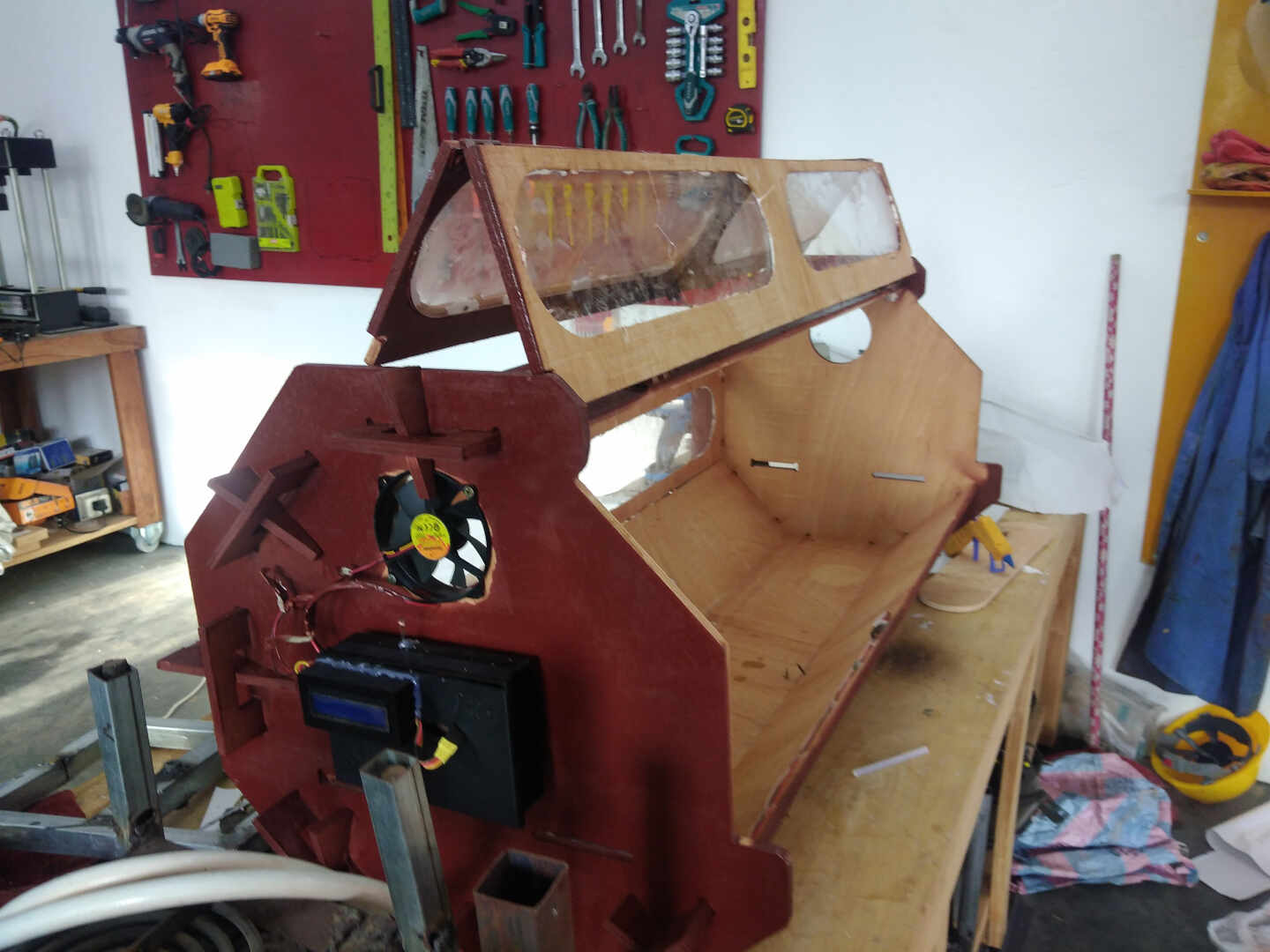
4. THE ASSEMBLY
This is the stage where all my components come together to form the full Smart Backyard Garden(SBG). During the production stage, I made subassemblies of the electronics and made a subassembly of the enclosure, now this is just me putting the subassemblies togethter to form the full and final assembly.
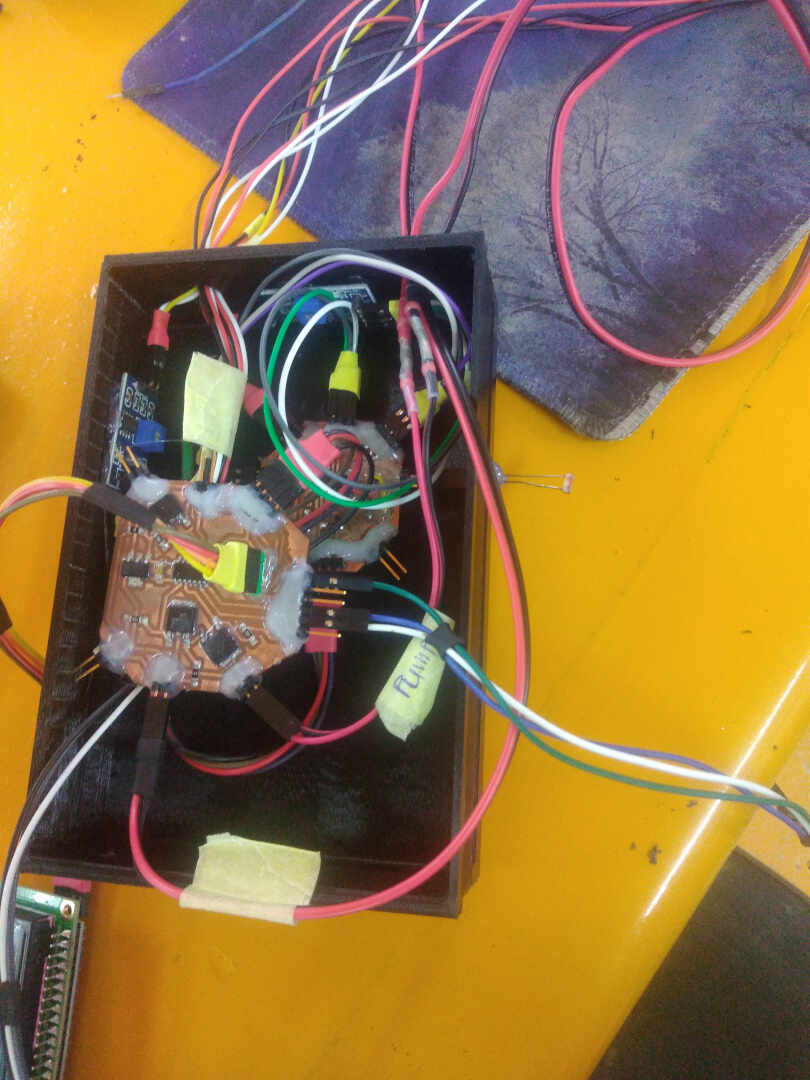
 connecting the sensors to the board and placing it in the case as well as testing to check for errors.
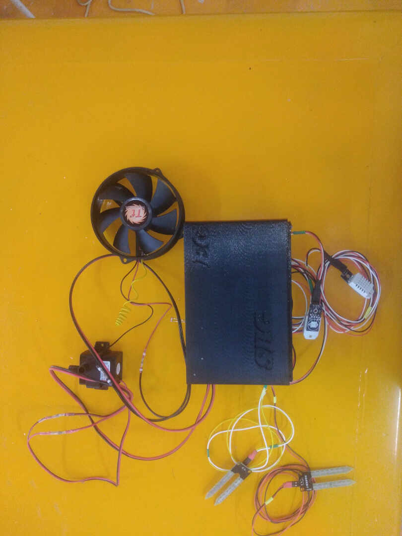
 connecting the wires
 finished connections
 closed the lid to check if it will close
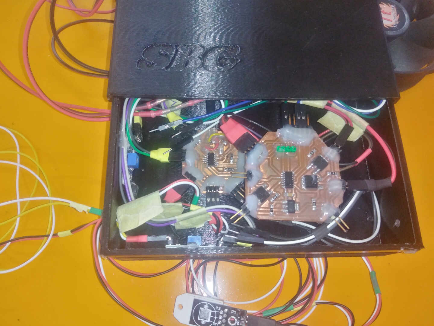
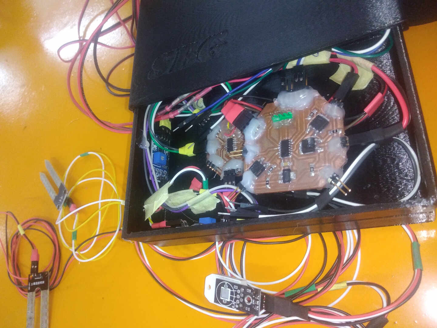 opened to show finished connections
 screwed the hanging slot for the case
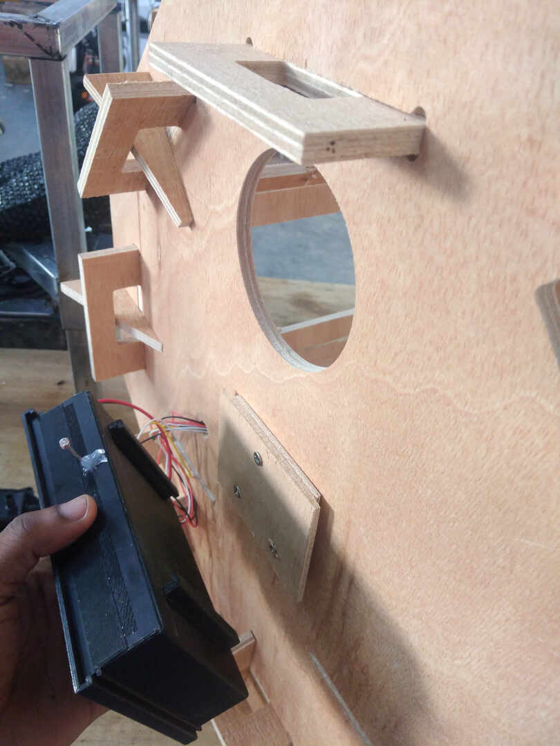 attaching the case to the enclosure
 case has been attached to the enclosure


 After spray painting
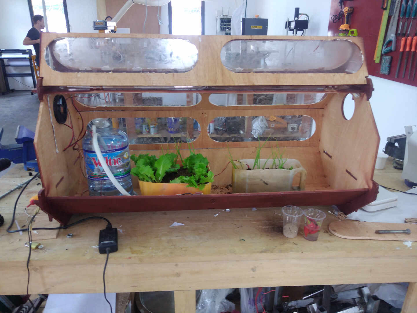 testing all whole system
the video above shows me removing the tape over the plexi windows after spray painting the enclosure.
the video above show me testing the ventilation system(fan) using a hair dryer blower to reduce the humidity and increase the temperature. When the temperature exceed 35 degrees the fan turn on.
the video above shows me testing the led lighting system by placing my finger on the photocell.
the video above shows the LED lighting up when the lights in the lab was turned off
5. THE FINAL RESULTS
After months of developing this idea and working tirelessly on the production of the parts and assembly, the video below shows the finished project. Enjoy!!!!
SUMMARY
In summary, the past 6 months have been spent honing skills from the Fabacademy programme to develop this idea in to a working prototype. These skills will go a long way to better my life and help my surroundings as I employ these skills to develop more sustainable technologies. It has been a great long journey full of fun and sometimes being hard.