8. Computer controlled machining
Welcome to this week’s assignment!, you can feel at home to go through ups and downs I faced this week. We worked on computer controlled machining using CNC machines to fabricate our projects. These are the tasks we had to do as a team am and individually
group assignment
  do your lab's safety training
  test runout, alignment, fixturing, speeds, feeds, materials, and toolpaths for your machine
individual assignment
  make (design+mill+assemble) something big (~meter-scale)
  extra credit: don't use fasteners or glue
  extra credit: include curved surfaces
Hero Shots

Group Task
As stated earlier, we were tasked as a group to test runout, alignment, fixturing, speeds, feeds, materials, and toolpaths for our lab CNC machine. which we had fun doing. It was a great experience for me since it was mine first time of actually working with a CNC machine.
CNC machine specs
1325 CNC Router Woodworking Machine buy.
| Machine Type | - 1325 Single Head CNC Router Woodworking Machine |
|---|---|
| Table Size | - 1300*2500mm |
| Countertop Structure | - Aluminum Profile Counter Top |
| Work Plan | - 13002500200mm |
| Bed Structure | - Welded Steel |
| XYZ Transmission | - XY Helical Rack Drive, Z Screw Drive |
| Guide | - 20 Square Rail |
| Maximum Empty Travel Speed | - 17000mm/min |
| Working Speed | - 15000mm/min |
| Spindle Power | - 3.2 kw JST Water Cooling spindle |
| Spindle Speed | - 0-24000rmp |
| Motor - Leadshine 860 | |
| Operating Voltage | - AC220V/380V, 50HZ |
| Run Command | - G Code |
| Operating System | - DSP/NC Studio |
| Distribution Cabinet | - Independent Cabinet |
| Support Software | - Type 3,Artcam,JD |
| Assist | - Dust Hood, Dust Tube |
So this is how things went down for the group task.
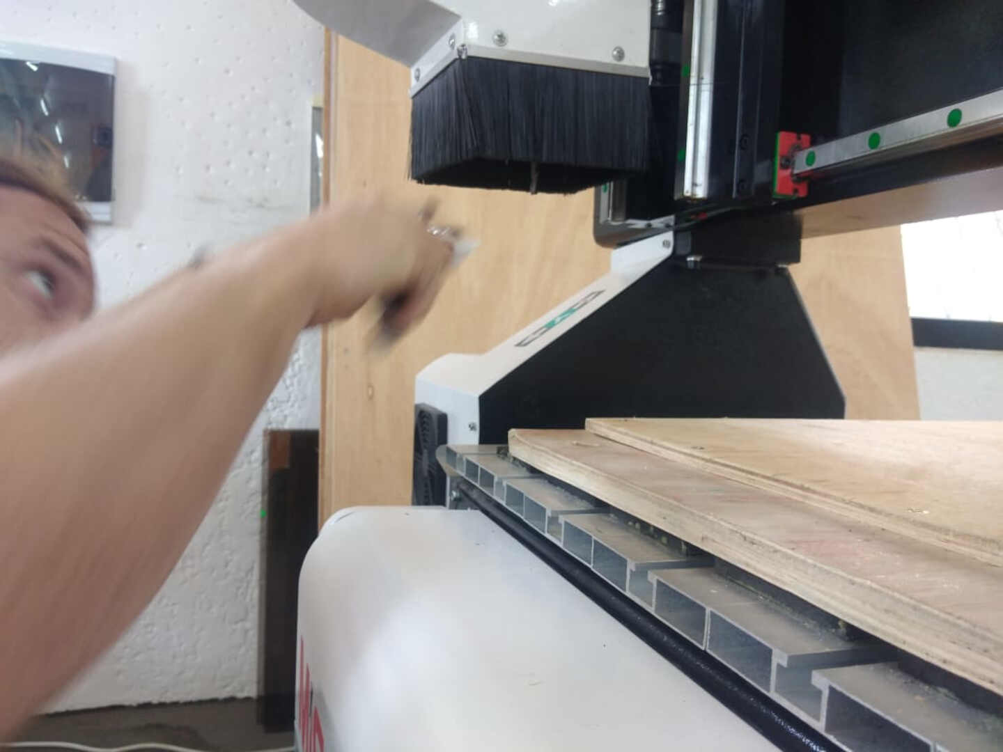
we had to load the plywood and secure it to the sacrificial layer of the machine
 image: this is us loading the plywood onto the bed of the CNC machine
Here you can see me securing the plywood to the bed using a hand drill and screws. Now the reason for this is that, we want minimal or close to no movement of the work piece.

The next thing is we turned the machine on. In the picture below, the button with light on is the power switch of the CNC machine and the green button below it is the power button for the vacuum machine and above it all is the emergency stop switch.

The next thing is to check if the water pump is in operation. We touched the water reservoir to feel the vibration of the water pump admist the noise of the CNC machine.

After all the necesaary checks, the tool bit we will be working with was loaded. A flat end up cut tool bit was used in all our milling and routing operations.
| Specifications | of the tool bit |
|---|---|
| Number of flute | - 2 |
| flute/cut diameter | - 6.35mm |
| flute height | - 33mm |
| shank diameter | - 6.35mm |
| shank length | - 43mm |
Once all these were done, we moved over to the software meant to control and feed the CNC with our desired set of operation instructions to be carried out. In this case the lab uses NCstudio 5.5.60 to carry out the milling operations on the CNC machine. it is easy to install, all you need to do is read carefully and follow the installation instructions.
Steps
Open the NCstudio software.

Manually move the tool stock by using the manual JOG buttons on the right side of the apd window.
Click operation
Click on move to refference point

Click on all axes, this should move the tool stock and the carriage to the machine’s home point.

Move to your zero point using the manual jog controls.
Zero all axes by clicking W.Coord on the tool bar of the software
Press f7 to accept and check zero point you set. (ps. the tool should move 50mm above the bed)
Once your origin has been set, you can move forward to load your file and start your operations.
Alignment Test
As part of our group task, we had to run the alignment test on our CNC machine to check how aligned our rails are. These rails are resposible for the X-Y-Z-axis movements on our CNC machine. if the machine fails this test, it would result in missalignment of right angled milling. So to run this test, we simply designed a square plate (100mm X 100mm and 141.4213mm across the diagonals) in freecad and milled it out on the machine.
| milling | parameters |
|---|---|
| spindle speed | - 20,000rpm |
| XY feed rate | - 200mm/s |
| Z feed rate | - 5mm/s |
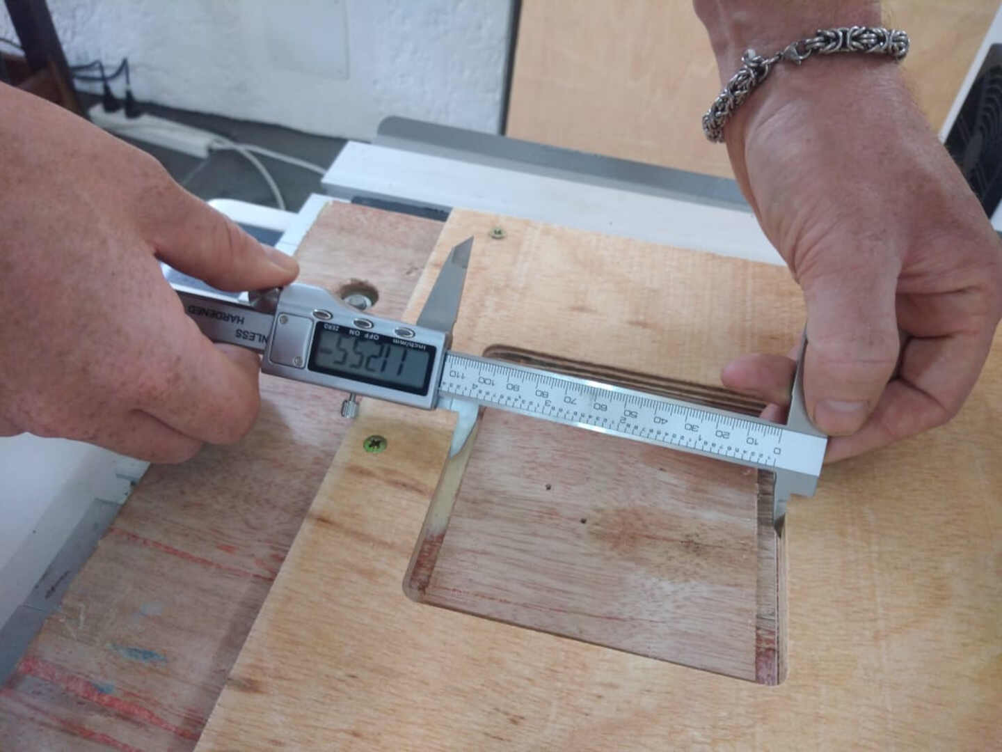
A digital vanier caliper was used to take the measurements. These are the images of the test and the out come.
The image below shows the milled square which was secured to the bed with screws because we did not add tabs to the operation.

In this image I unscrewed the piece for measurements

This side was measured and had a value of 100.04mm as compared to the specified 100.00mm

This side was measured at 100.02mm as compared to the specified 100.00mm

this diagonal was measured at 141.37mm as compared to the specified 141.4213mm

This diagonal was measured at 141.04mm

These immage shows the measurement of the interal length of the cut being measured.

## Additional test We decided to run one more test, now this test is in relation to our material. we conducted a tolerance/fit test for our material and joint fiting. So in this test we made finger joints with various dimensions from 8.4mm to 8.8mm to test the fit of the materials.


So at the end of this test, we concluded that a slot with 8.8 as the diameter will be the best for a fit joint.
Fixturing
We added a sacrificial layer of plywood to the aluminum bed of the machine and then secured the work materials using screws and plastic nuematic nails.
Runout test
we were asked to test the runout of the CNC machine’s spindle.
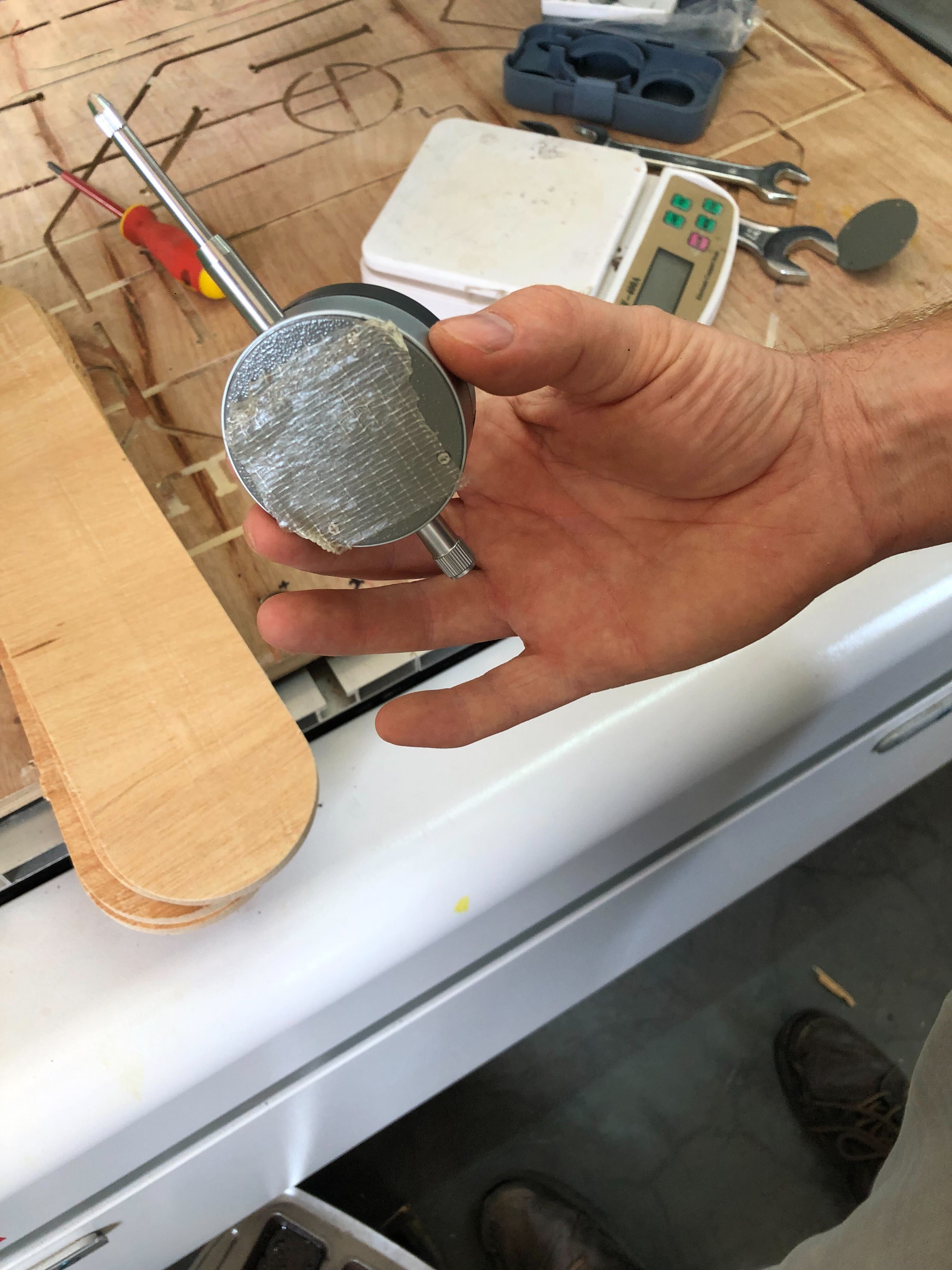 a double sided tape was used to secure it to some planks of wood.
 setting the tool in place
 making contact with the clindrical part of the spindle
the video above show the testing

The Neotech digital dial was used in this test specifications:
- Large LCD Display with 3 Digits
- Measuring Range from 0 ~ 25.4 mm (0 ~ 1 inch)
- High Resolution up to 0.01 mm (0.0005”)
- Switchable between mm and inch
- Zero Setting
- Response Time: ≤ 0.5 m/s
- Operating Temperature: 0 ~ 40 ℃ (32 ~ 104 ℉)
- Storage Temperature: -20 ~ 70 ℃ (-4 ~ 158 ℉)
- Relative Humidity: ≤ 80% R.H
- Material:Aluminum Alloy
- Power: 1 x 1.5 V LR44 Button Cell Battery (Included)
- Item Size: approx. 122 (L) x 55 (W) x 26 (D) mm (4.80 x 2.17 x 1.02 inch)
- Item Weight: approx. 129 g (4.55 oz) (battery included)
Completing our lab’s safety training
For the safety training, we were required to put on safety personal protective equipment like:
- Safety glasses to protect our eyes
- Ear plugs to block loud noises
- leather gloves to prevent splinters when handling the wood pieces.
- make sure the blower and water pump were working to avoid any fire hazards.
So after running these tests on our CNC machine(Big Bertha), It passed the following test:
- Alignment test
- Runout Test
- The tolerance/fit test with our materials
- Fixturing
Individual Task
You remember I said I had some ups and downs, unfortunately all the downs I faced was during my individual task. So I decided to machine out the parts of my final project designs. It is the housing of the Smart Backyard Garden.
 image: this image shows the complete assembly of the project. it has 5 different pannels that comes together to make the green house.
I used solidworks to 3d model the whole projetc and I used solidworks CAM to define and generate the CNC tool paths. So I will take you through the processes T had to take to avoid the errors I made.
so the first thing you want to do after you have your part ready to be machined, is add your Lab’s machine to solidworks machines.
Click tools from the arrow on the title bar.
Click Solidworks CAM.
Click on Technology Database.
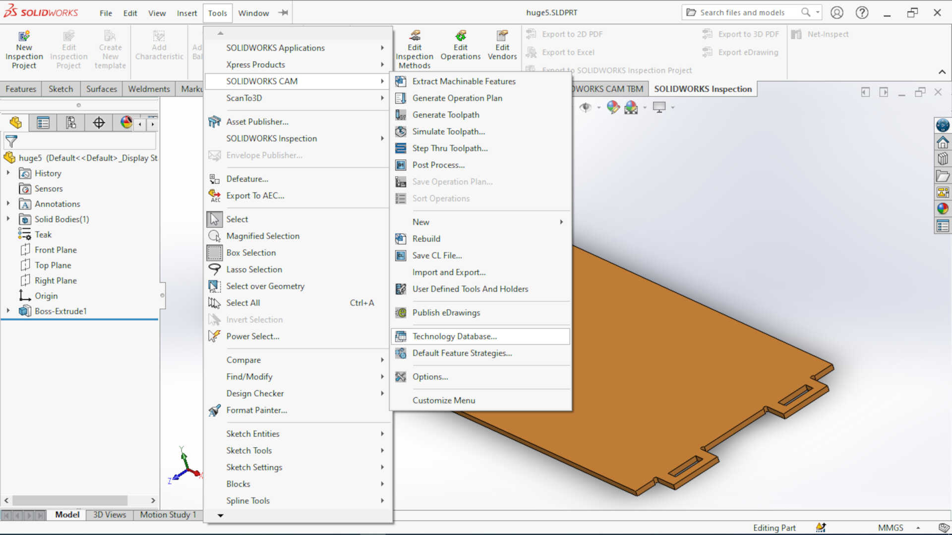
click on existing machine and the click copy to create a machine you can edit the parameters to match your Lab’s nachine

You can now edit the parameters to match your machine and then click save to save and add your newly defined machine.

Now you have sucessfully added a machine, you need to add a post-processor to machine your CNC machine controller. First of all, you need to download a post-processor library. you can find some free ones here. Once you download it extract to this location C:\ProgramData\SOLIDWORKS\SOLIDWORKS CAM 2021\Posts\Mill in your computer. Once you are done with this, open solidworks and open your part.
Go to your Add-ins manager and load solidworksCAM.
-click on the solidworksCAM tab.
-click on machine definition and select the machine you added and click select. It should display the speeds you set

-click on the next tab in the machine definition window(ie Tool crib), here you can select the tool class and crib you want to use or you can create a new tool class and crib.
 Image: I was editing the cutting parameters of a tool I intended to use.
-Move on to the Post processing tab still in that window, click browse to select the post processor file you added to the directorate.

The next thing we want to do is set our stock parameters in our stock manager
So, in the CAM tree double click on the stock manager
 and then set your stock dimentions in either the X-direction, Y-direction or the Z-direction
Next we set our fixture coordinates, that includes the orgin of the work piece.
 you can pick any vertex as your orign but I would recommend you select ine of the end vertex of the stock.
Next you have to use the extract machinable features from the CAM tab in the enu toolbar. this will scan the workpiece and give features your machine can work on.
The next thing is to click on 2.5D axis machining operations in the CAM tab
 In the picture above, you have options to pick the type of operation you are performing
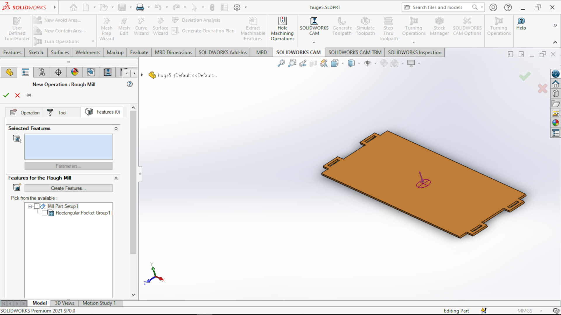 you select the features to apply the operation you selected.
The next thing to do is click on the generate operation plan command. This will automatically generate the plans for the operation which you can edit.
the next thing is to add tabs to your plans. Right click on the operation under sill setuo in the CAM tree and then click edit definition. at the bottom right sid of the popped up window, tick Tab cutting

 you can set the dimensions of the tab and select the feature to apply it to.
Now we to generate the tool path of the machne
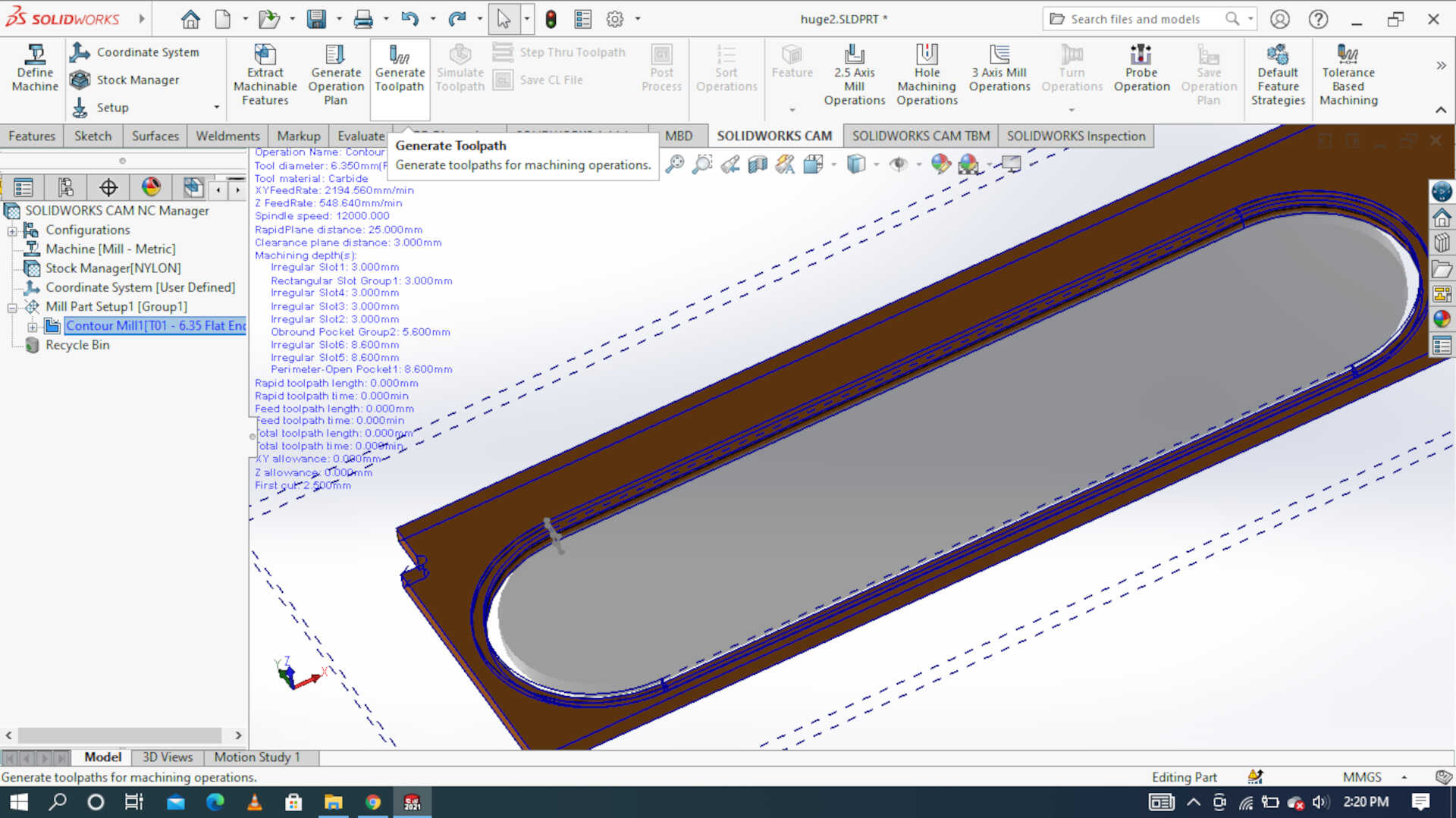 After you have generated the toolpath you can simulate to see it for yourself.
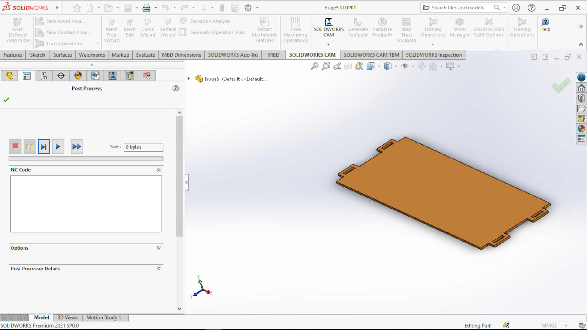
Now it is time to export the CAM file as a .NC file for the CNC machine to run. Click the post process command and specify the name you want and where you want. make sure you change the file type to .NC before you hit save. The imange below is what will appear when you click the save button. Just hit the play button and click the done symbol.
Now this is where all my troubles started, after I had done these procedures our printer had issues with the codes. I had a tough time debugging the codes to find the problem but like we say in my language “Nasar beini” (meaning there is victory), I found the problem and fixed it so I could machine my parts. There were two problems, one is that the initial and final tool paths Z-travel was way beyond our machine so the machine would not work and then it always goes back to the absolute origin of the machine instead of the one set for the work piece.
These pictures shows the tool paths in solidworks NC code editor. these are the unedited codes. The parts highlighted in yellow are the lines of codes responsible for the errors I faced
 image: begining of the operation
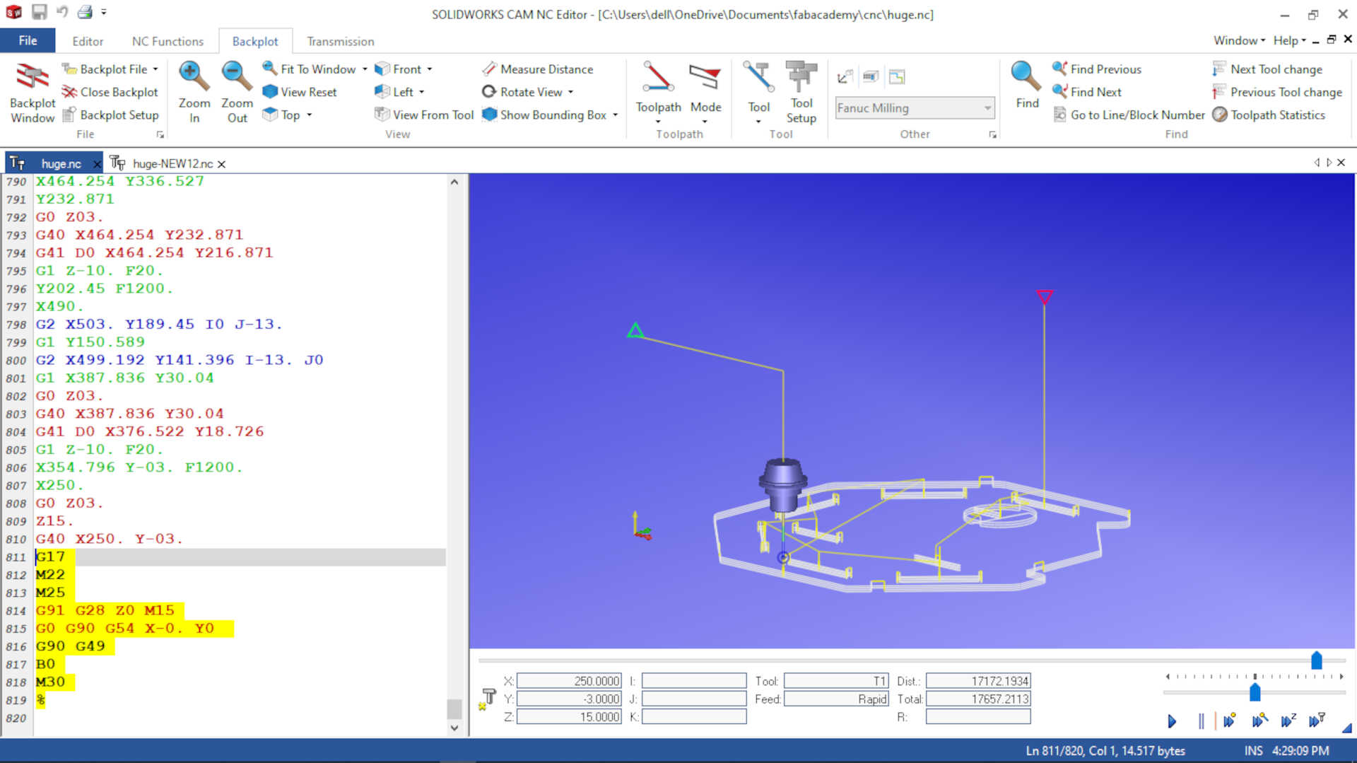 image: End of the operation
These pictures shows the tool paths after I edited them to work on the CNC machine. The highlighted codes shows the Edited parts.
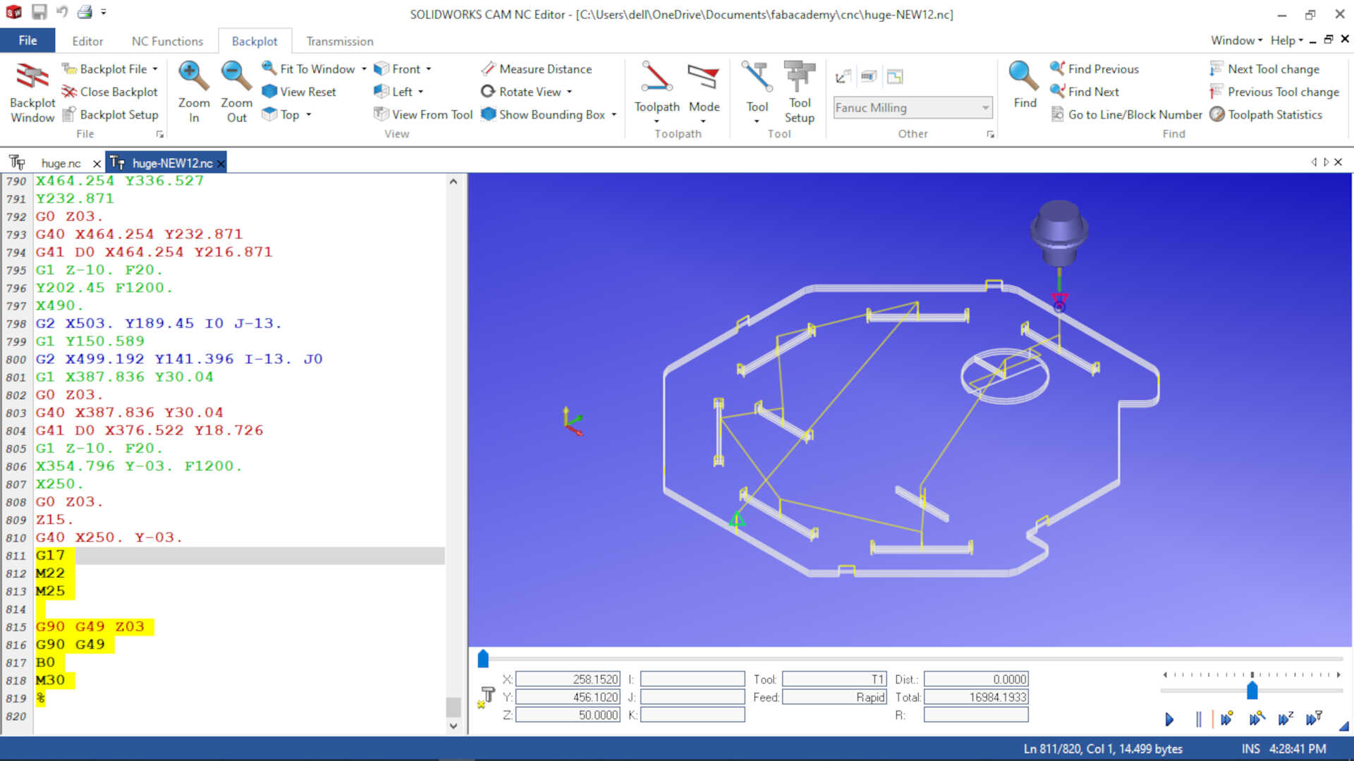 image:end of the operations
 image: begining of the operation
These are the lines of codes that casued the problem and the codes that I used to fix my problems.
starting codes
 %
 G91 G21 G40 G49 M22
 B0
 G8 P1
 T1 (6MM CRB 2FL 19 LOC)
 M13 S20000
 G0 G90 G0 G54 X258.152 Y456.102
end codes
 G17
 M22
 M25
 G91 G28 Z0 M15
 G0 G90 G54 X-0. Y0
 G90 G49
 B0
 M30
 %
new starting codes
 %
 G91 G21 G40 G49 M22
 B0
 G8 P1
 T1 (6MM CRB 2FL 19 LOC)
 M13 S20000
 G0 G90 G0 G54 X258.152 Y456.102 Z50
new end codes
 G17
 M22
 M25

 G90 G49 Z03
 G90 G49
 B0
 M30
 %
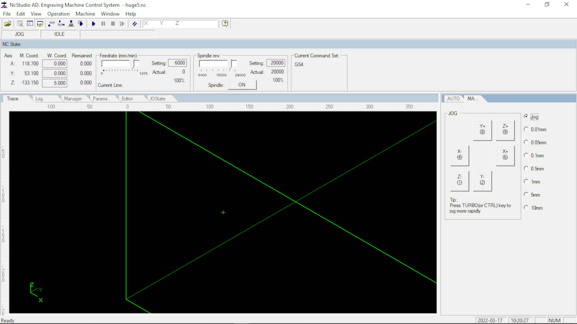
This image shows a simulation in the NCstudio software

Files
I hope you enjoyed this week and found this helpful. Thank you for passing by.
What went wrong?
I had issues with the G-code Solidworks generated for the CNC machine in the lab. It was all because the CNC machine was not available in the mcahine selection section. I fixed this by editing the G-code manually
What went well
The CNC cut outs came out nicely done and the parts fitted perfectly
wrapping up
I got to do test on the CNC machine to determine the runout of the spindle, I learnt how to add new machine libraries to Solidworks, it was a great experience. I got edit G-codes to suit our machine and learnt rules of operating a bigger CNC machine.