14. Networking and communications
Welcome to this week’s assignment. This week we learnt how to communicate between two devices/microcontrollers in this case I communicated between my input board and output board using the arduino IDE as the programming platform and the I2C protocols.
Assignments
-
Individual assignment: design, build, and connect wired or wireless node(s) with network or bus addresses
-
Group assignment: send a message between two projects
Group assignment
This week we were tasked to send a message between two projects, so we decided to send information from Pacome’s board(uses an ESP32 chip) to my OUTPUT board(using an AT-tiny 1614 chip) using the I2C transfer protocols. I will talk about the I2c protocol in my individual assignment.
Two set of codes were written by both of us to accomplish this task. I was in charge of programming my board to receive the message from his board and then act on the message. We used a soil moisture sensor as the input device and Pacome’s board was resposible for transmitting the information from the input device(soil moisture sensor). My board received the information and performed the action by activating sumersible water pump. You can see the setup in action in the video below.
The two sets of codes are bellow
For the OUTPUT BOARD
#include <LiquidCrystal_I2C.h>
#include<Wire.h>
#define SECOND_ADDR 9
LiquidCrystal_I2C lcd(0x27,16,2);
int x;
int pump = 1;
void setup() {
  // put your setup code here, to run once:
pinMode(pump, OUTPUT);
Wire.begin(SECOND_ADDR);
Wire.onReceive(receiveEvent);
Serial.begin(9600);
}
void receiveEvent()
{
 x=Wire.read();
 }
void loop() {
  // put your main code here, to run repeatedly:
if (x<=40)
{
  digitalWrite(pump,LOW);
  Serial.println("Pump Off");
  }
else
{
  digitalWrite(pump,HIGH);
  Serial.println("Pump On");
  }
}
For the INPUT BOARD
#include <Wire.h>
#include <LiquidCrystal_I2C.h>
#define SECOND_ADDR 9
LiquidCrystal_I2C lcd(0x27,16,2);
int sensor_pin = 34;
int x = 0;
int value ;
void setup()
{
  Wire.begin();
  Serial.begin(115200);
  Serial.println("Reading");
}
void loop()
{
  value= analogRead(sensor_pin);
  Serial.print("Moisture : ");
  x=map(value,0,4095,0,100);
  Serial.println(x);
  Wire.beginTransmission(SECOND_ADDR);
  Wire.write(x);
  Wire.endTransmission();
  delay(500);
}
Individual Assignment
In my case, I did not need to design a new board for this assignemnt since I have all the boards I need for my project designed-the input board and output board.
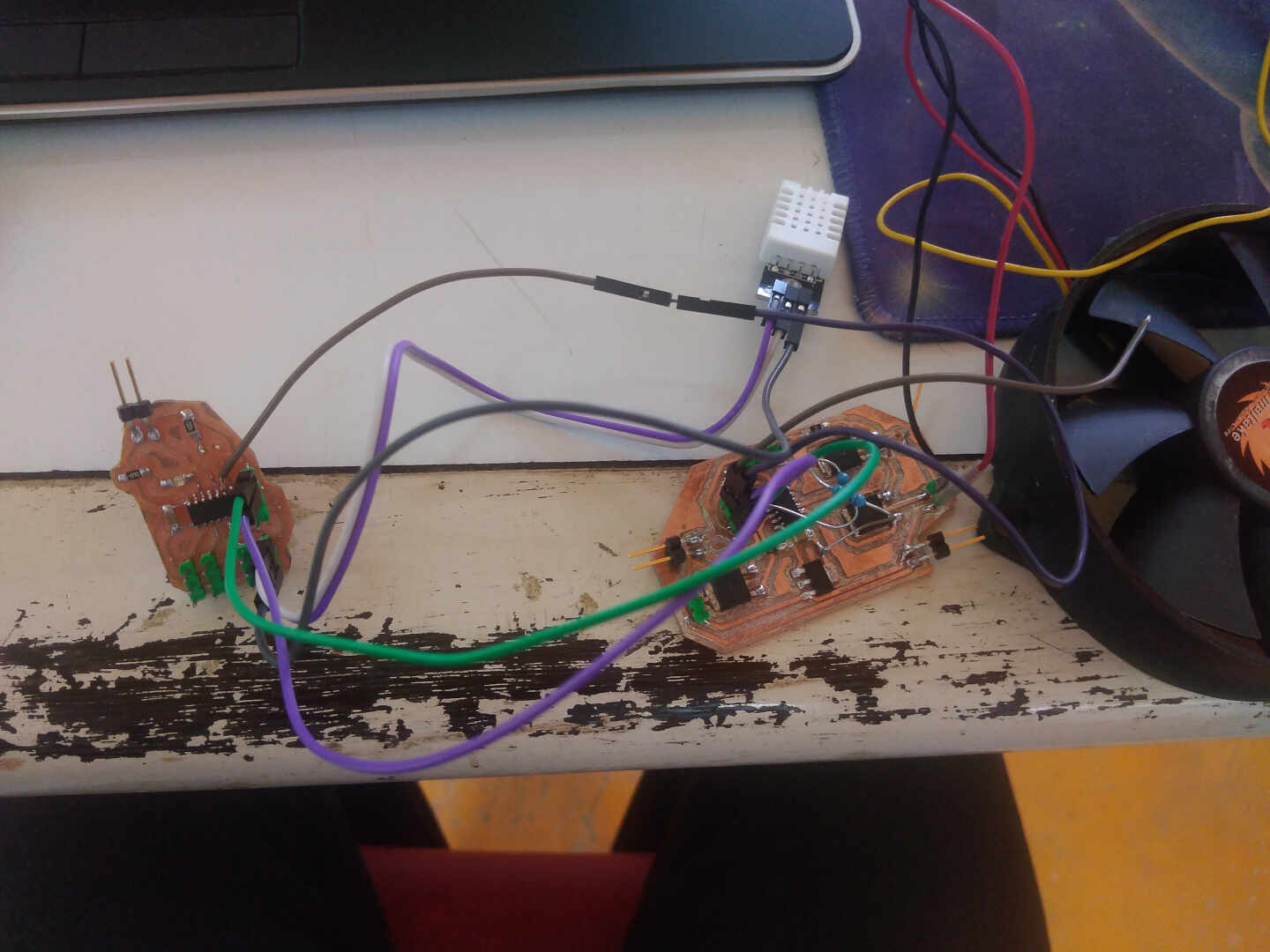
HERO Shots
This is my hero shots of my input and output boards connected with the sensor(input device) and the fan(output device) connected.
Mode of communication
I used the the Inter-Integrated Circuit (I2C) mode of communication. the Inter-Integrated Circuit (I2C) protocol is taking over because you need fewer pins; only two, no matter how many Staff you’re connecting (up to 1008). I2C also allows for more than one Manager.
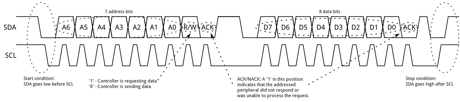
The two lines of I2C are SDA, the data signal, and SCL, the clock signal. Both the SDA and SCL line are connected to VCC with ±5kΩ resistors to restore the lines to HIGH when no device is actively trying to pull it LOW.
Within the I2C protocol messages are split into two types of frames:
Address frame | In this frame the Manager will indicate which Staff member it wants to send data to. It is always the first frame in any new communication sequence. For a 7-bit address, the address is send out most significant bit (MSB) first, followed by a R/W bit indicating whether this is a read (1) or write (0) operation. The 9th bit of the frame is the NACK/ACK bit ((not)-acknowledge). This is the case for all frames (data or address). Once the first 8 bits of the frame are sent, the receiving device is given control over SDA. If the receiving device does not pull the SDA line LOW before the 9th clock pulse, it’s assumed that the receiving device either didn’t receive the data or didn’t know how to parse the message. In that case, the exchange halts, and it’s up to the Manager of the system to decide how to proceed. Data frame(s) | These 8-bit frames contain the data being send. This is send along the SDA line by either the Manager or the Staff, depending on whether the R/W bit in the address frame said it should be read or write. There is a start condition; To initiate the address frame, the Manager device leaves SCL HIGH and pulls SDA LOW. This puts all the Staff members on notice that a transmission is about to start.
Once all the data frames have been send, the Manager will generate a stop condition. These are defined by a LOW to HIGH transition on the SDA line after a HIGH to LOW transition on the SCL line, with the SCL remaining at HIGH (thus during any data transmission, the SDA line should not change when SCL is HIGH).
To program with I2C you can use the Wire library in the Arduino IDE.
See this page on Sparkfun for more information about I2C and the more complex ways of communicating, such as 10-bit addresses, repeating start conditions and clock stretching.
Programming My boards
The Master board
I chose the input board to be the master board to send the instructions to the other board.

I did state earlier on that I used the arduino IDE to write the program and upload it unto the boards.
The Master program
#include <DHT.h>
#include<Wire.h>
int q = 0;
#define SECOND_ADDR 9


#define DHTTYPE DHT22

#define DHTPIN1 3
#define LED 9
DHT dht1(DHTPIN1, DHTTYPE);

float hum1;
float temp1;

void setup() {
  // put your setup code here, to run once:
dht1.begin();
Wire.begin();
pinMode(LED, OUTPUT);
}

void loop() {
  // put your main code here, to run repeatedly:
hum1  = dht1.readHumidity();
    temp1 = dht1.readTemperature();

    if (temp1>=32)
    {
      q = 1;
      digitalWrite(LED, HIGH);
    }
    else
{
  q = 0;
  digitalWrite(LED, LOW);
  }
   Wire.beginTransmission(SECOND_ADDR);
   Wire.write(q);
   Wire.endTransmission();
   delay(500);
}
In the first part of the code; - I defined the pins the sensor is connected to
-
the pin the LED is connected to
-
included the Wire and DHT22 libraries
-
defined the temperature,humidity and Q variables
-
defined the pin type for the DHt22 sensor
In the void setup I; - initialized the DHT22 sensor
-
initialized the Wire mode
-
Set the pinMode for the sensor to be an input
In the void loop, I; - wrote to the sensor to read the values of the humidity and temperature
-
put and if&else condition for the system to satisfy and act on
-
put the transmision code once the condition that was set is met.
The slave board

The Slave Program
#include<Wire.h>
#define SECOND_ADDR 9
#define pump 0
int q ;
//#define fan 1
//#define led 9
void setup() {
  // put your setup code here, to run once:
Wire.begin(SECOND_ADDR);
Wire.onReceive(receiveEvent);
//pinMode(led, OUTPUT);
pinMode(pump, OUTPUT);

}
void receiveEvent()
{
  q=Wire.read();
}
void loop() {
  // put your main code here, to run repeatedly:
//digitalWrite(led, HIGH);

digitalWrite(pump, q);
//delay(500);

//digitalWrite(fan, LOW);
//digitalWrite(led, LOW);
//digitalWrite(pump, LOW);
//delay(10000);

}
In the first part of the program, I; - defined the pin the fan is connected to
-
defined the second address for the communication
-
included the Wire library
in the void setup, I; - initialized the Wire
-
initialized the receiving for the slave
-
set the pinMode for the fan
in the void receiveEvent; - it will act on the set of instructions received from the master if there is any.
In the void loop; - the fan will be switched on or off depending on the instructions received from the master.
What went Wrong?
I made some errors in my output board design. I did not add 5k ohm pull down resistors to my SDA and SCL lines/traces hence I had to hand solder/jump with some regular 5K ohm resistors to enable me to use the SDA and SCL pins for the I2C coummincations.
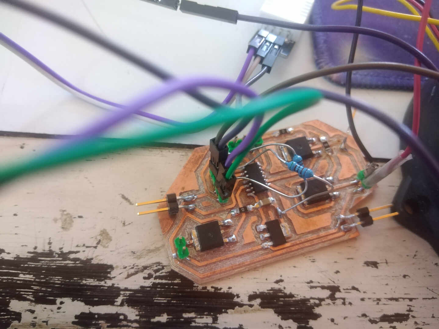
This was later corrected from redesigning the of the whole board adding the missing components and rearranging them. You can check the changes here for further understanding.
what went well?
After I fixed what went wrong, every thing fell according to plan at a good pace.
what I would do differently?
I would add more conditions and fuctions to the codes.
Wrapping up
this was an interesting week, learning how to communicate between two boards was really fun. Thanks for sticking around.