Introducing Zorro
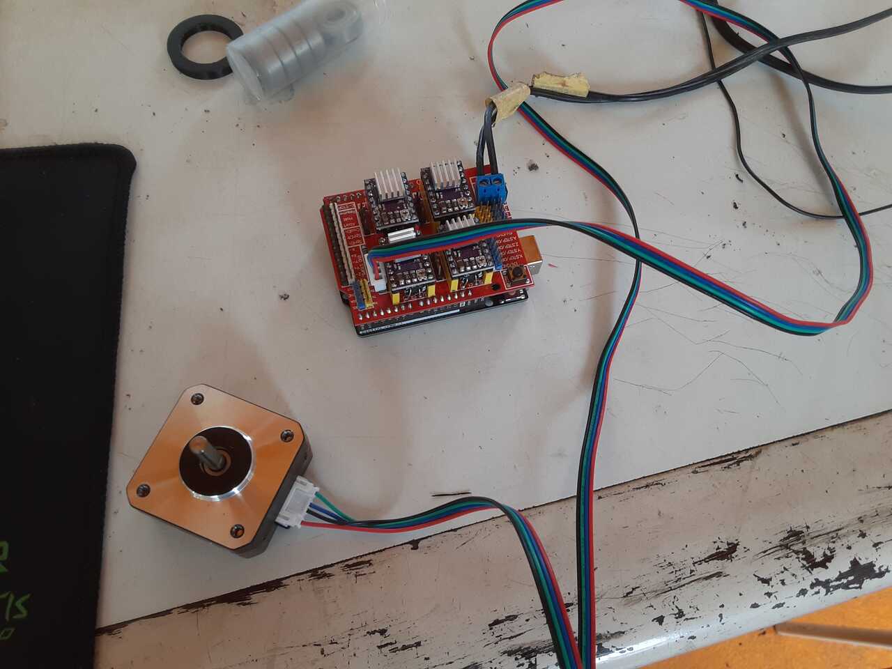
Zorro is the newest addition to our machine family, A styrofoam cutter that likes to leave its mark. Made from extruded aluminum, Nema motors, an Arduino/CNC shield, and some recovered parts from an old hair dryer, old Zorro brings new life to used things. Zorro will be used in our lab to make 3D styrofoam models for lost foam aluminum molding. The objective is to make aluminum molds for a plastic injection molding machine. The mission is to help solve West Africa’s garbage surplus and find ways to valorize was and incentivice locals to upcycle their discarded materials.
Hero Shots
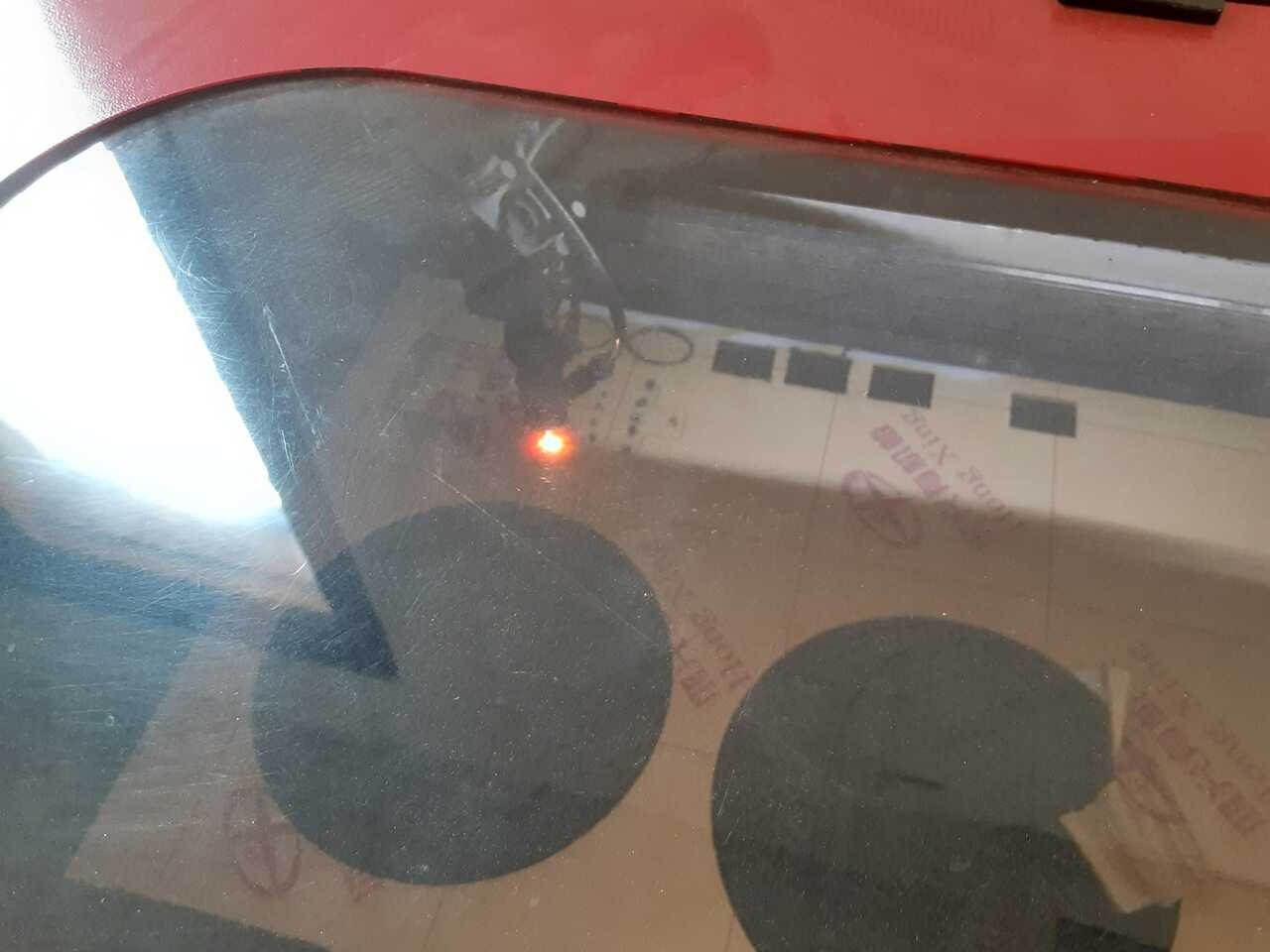
Video above: Testing that the electronics and mechanisms work
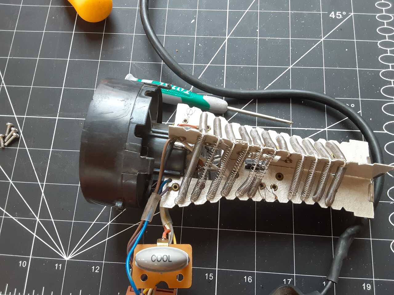
Video above: Testing the heater wire that was recovered from an end of use blow dryer to check that it will work.
Construction
The construction of the machine consisted of three or four main elements and sub-assemblies. The main elements were:
- The frame and its assembly
- The mechanisms and their assembly
- The wiring and its parts
- The programming of the electronics
The following sections will walk through all of these in detail.
Frame Assembly
The core elements of the frame were made from extruded 20x20 mm aluminum. This is pretty standard method for building DIY machines.
The feet, and roller plates for the translational axes were made by cutting plexiglass using Bumblebee, our laser cutter. The motor suports and pulley supports were 3D printed using Nemo our 3D printer.
Details regarding the design and assembly process are included below.
Cad modelling and design
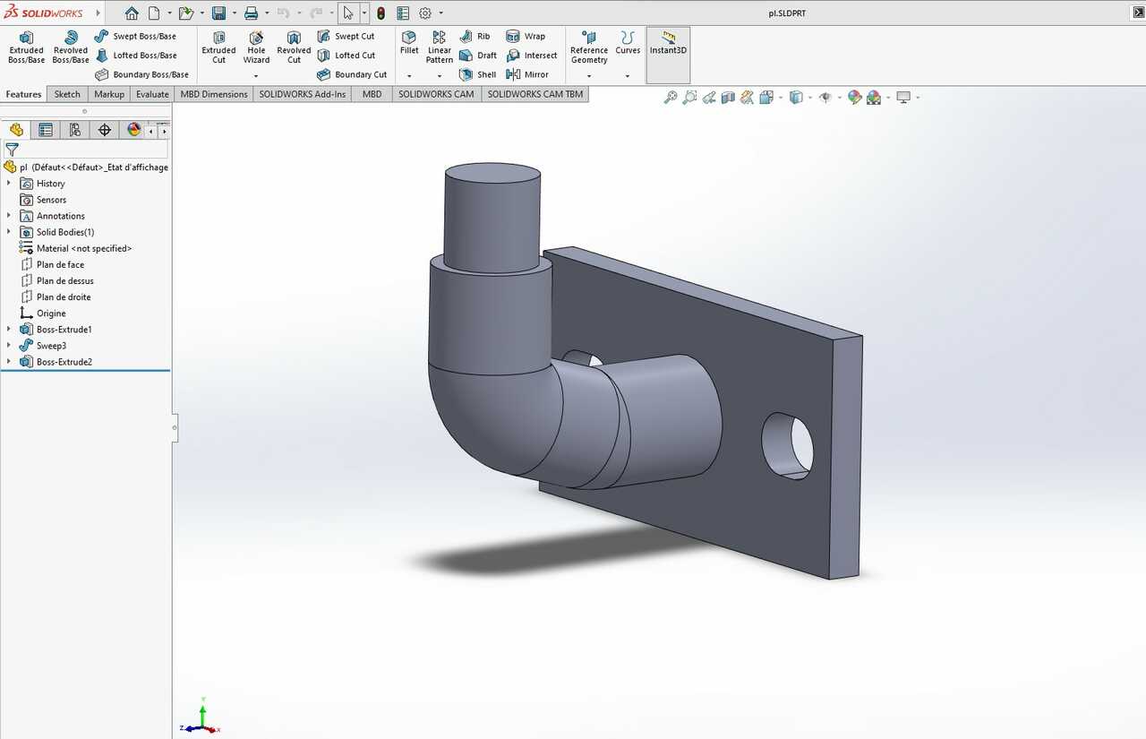
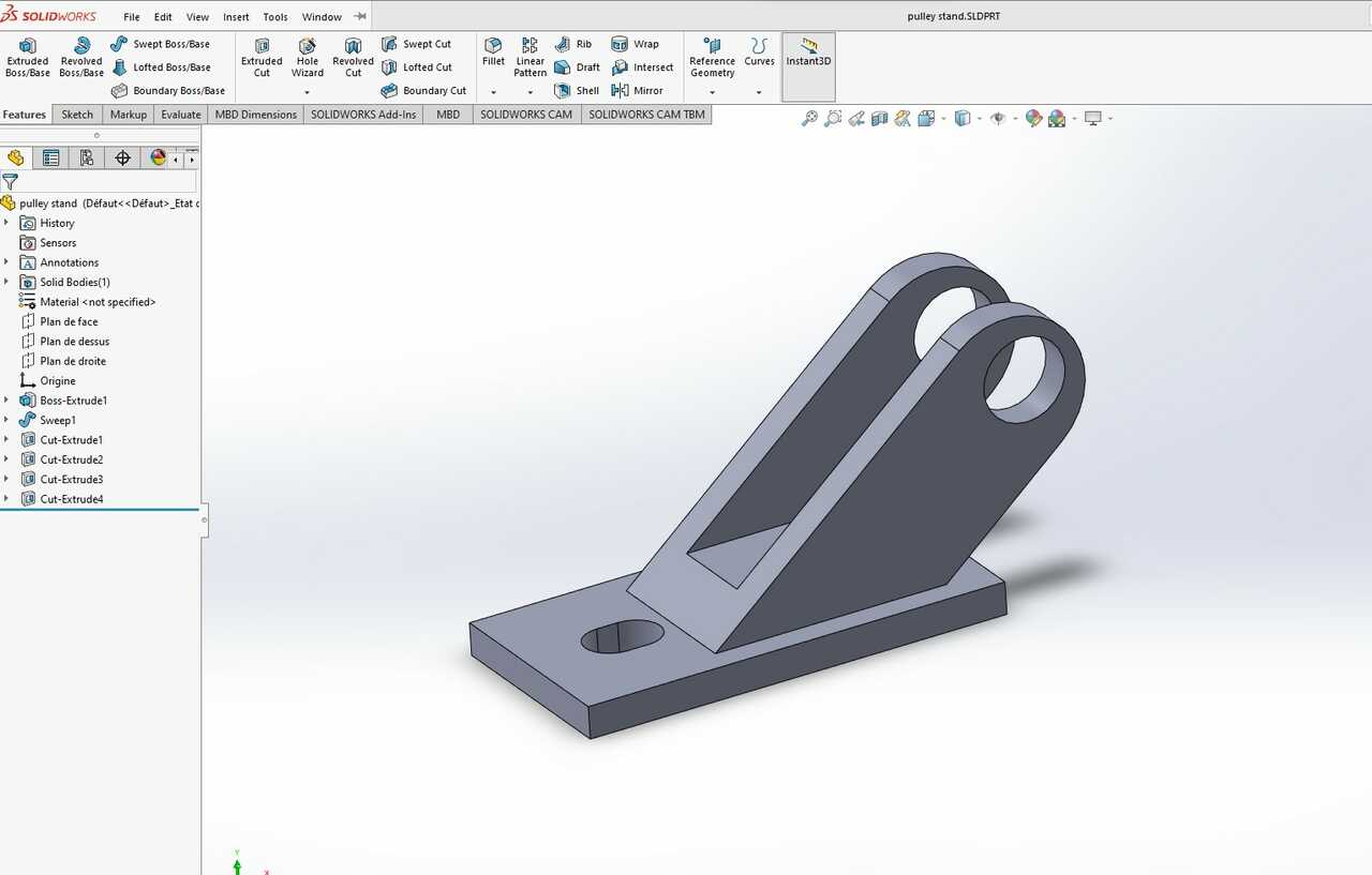
Our amazing student Edward Faako did a considerable portion of the frame design using Solidworks. You can see some of the models he produced below.
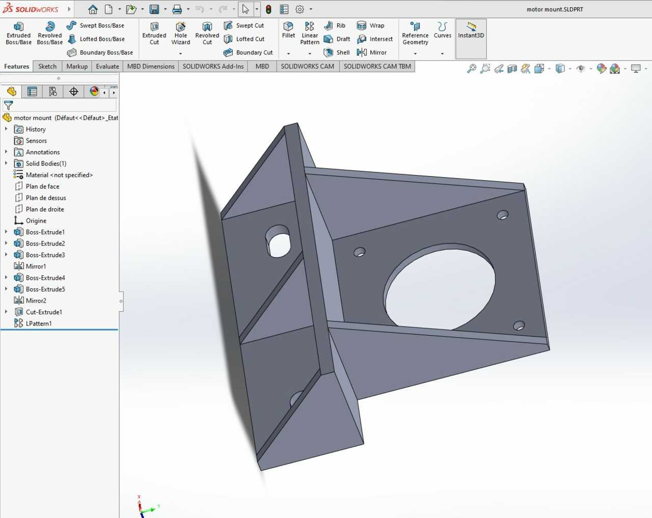
Next we will discuss the assembly and the methods used.
Assembly
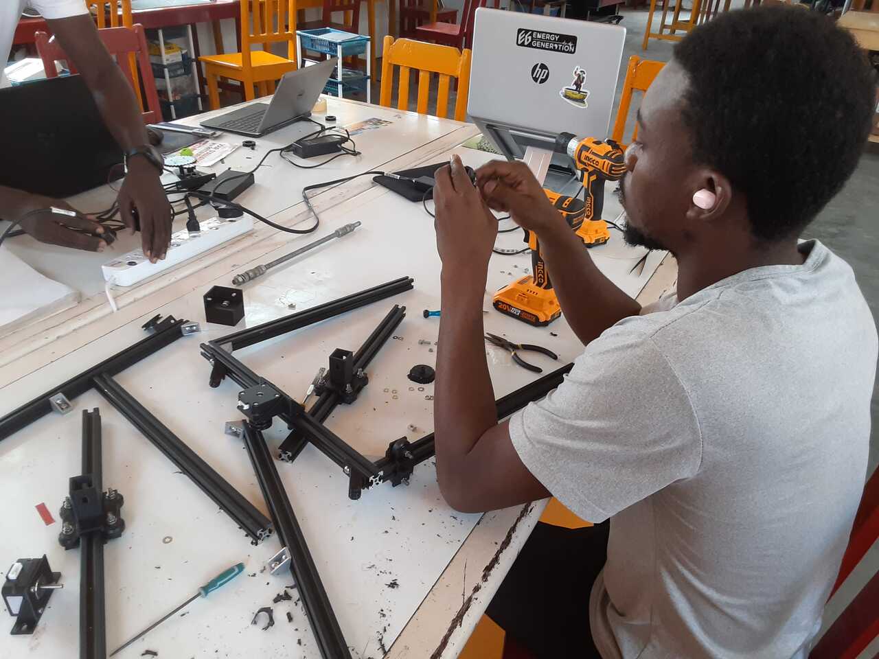
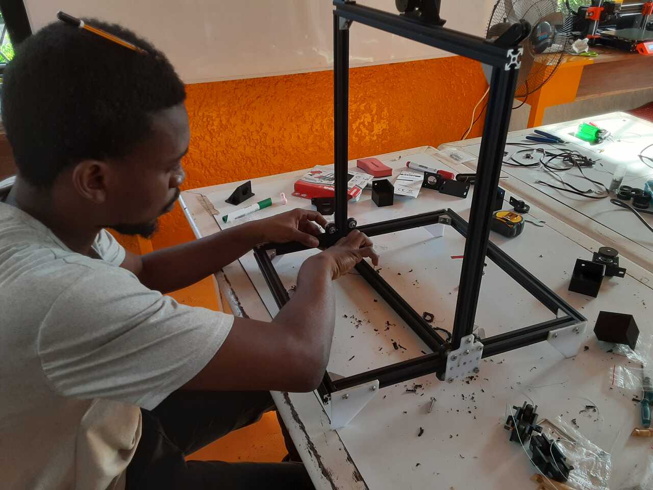
As you can see in the photos below, we have Edward Faako working on the assembly. There were numerous iterations required and redesigns to ensure that the rollers worked properly. At first the roller mounts were 3D printed, but the design led to some friction and binding, so we had to rething the design.
Takins sum inspiration from the Urumbu Project, we did some minor redisgns on the bearing plates and got to the laser cutter. This greatly reduced our iteration time as we were able to try designs in a matter of minutes, rather than waiting hours for a 3D print to finish.
In this photo you can see the laser cut bearing plates and feet after they had been installed on the frame. Edward Faako was so focused we were able to through pencils in his hair without him noticing :P (jokes, he put the pencil there himself).
Mechanism installation
The machinisms we opted for were of two kinds. The first was a pulley system to control the x and y translational axes. The second mechanism was a gear based mechanism to rotate the table for the z rotational axis.
The mechanisms was constructed and assembled using a combination of 3D printing and of laser cutting the various components.
Cad modelling and design
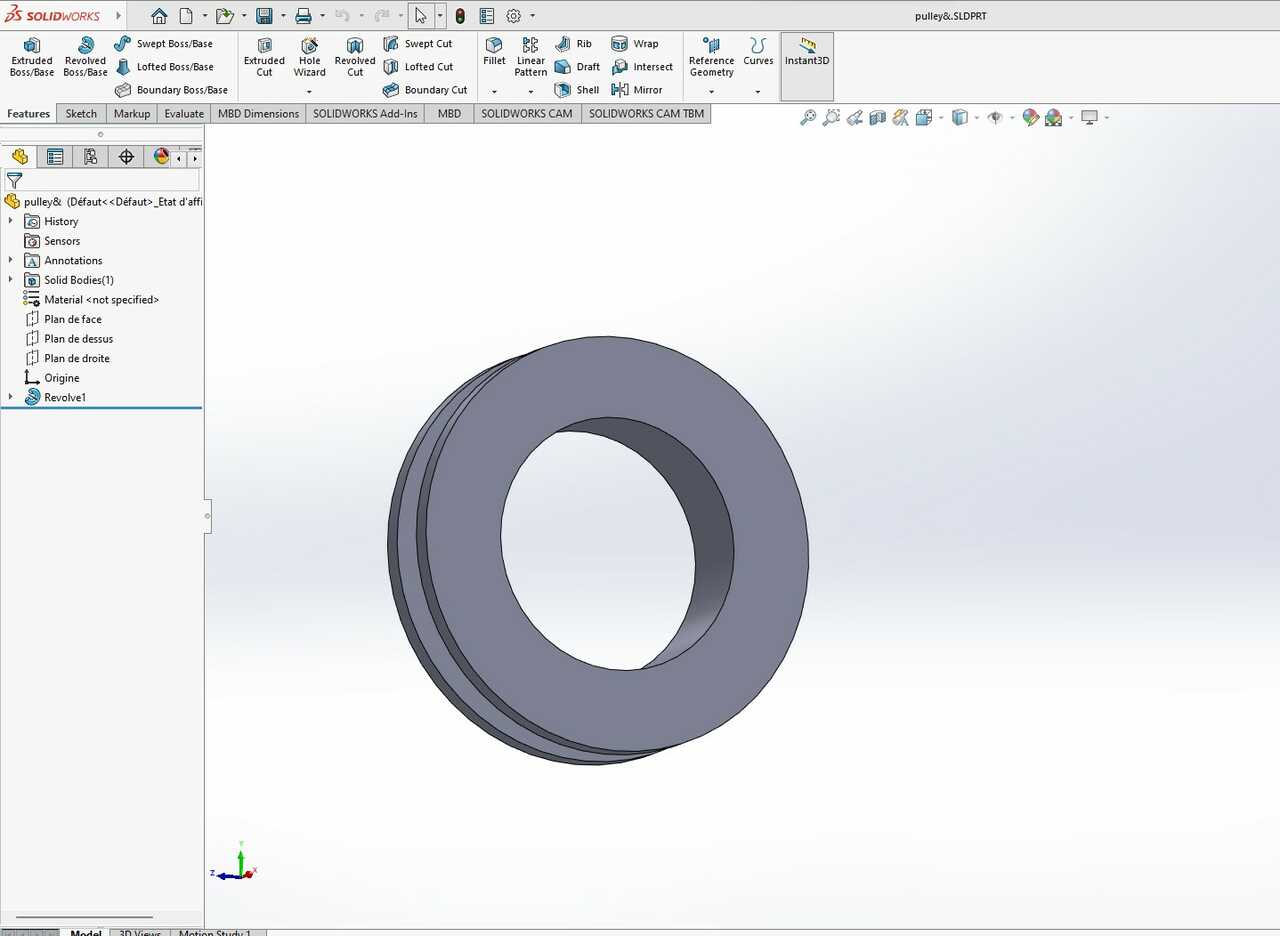
The pulley system CAD modelling is shown below:
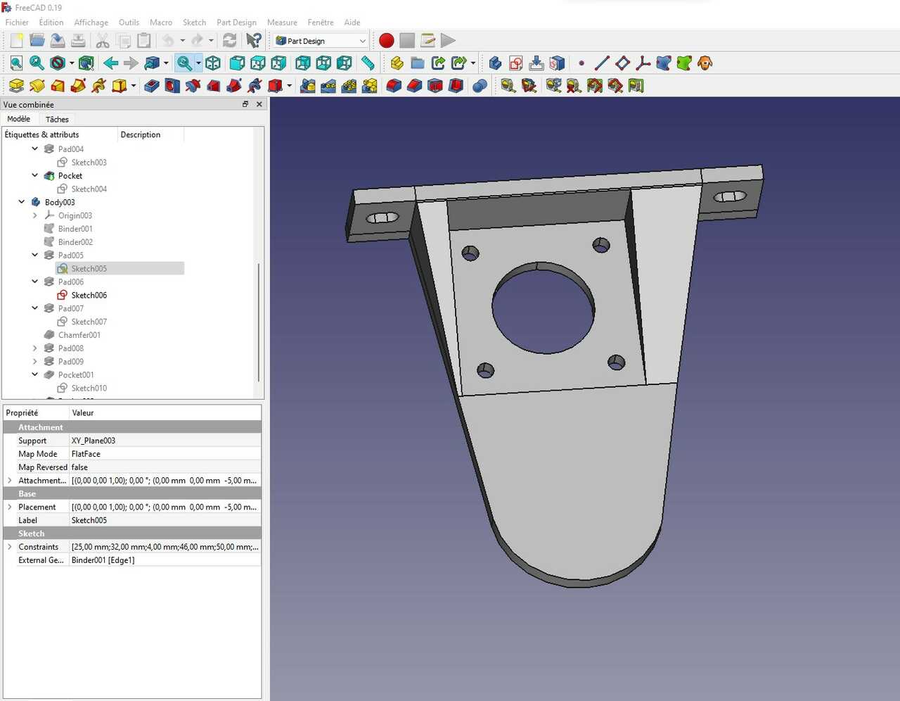
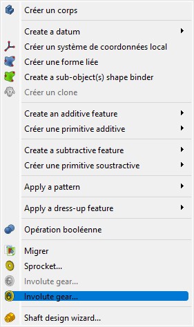
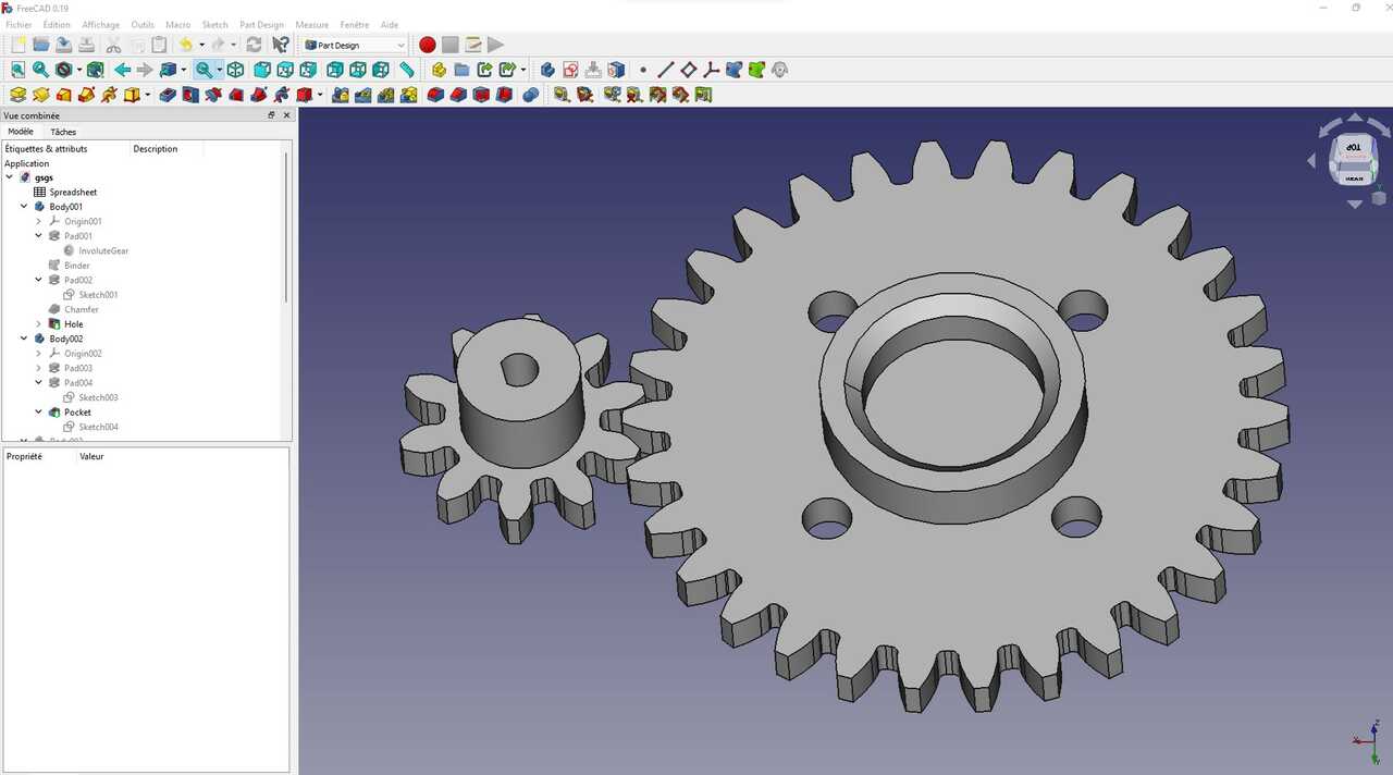
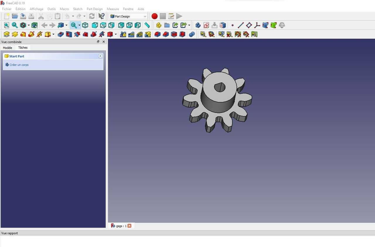
The second system, the gear based system, was designed by Pacome Kpodar and was modelled using FreeCad’s gear creating tool. In the Part Design Workbench you can select the “Involute gear…” option from the Part Design dropdown menu as shown below. This will lead you to the workbench to design your gear.
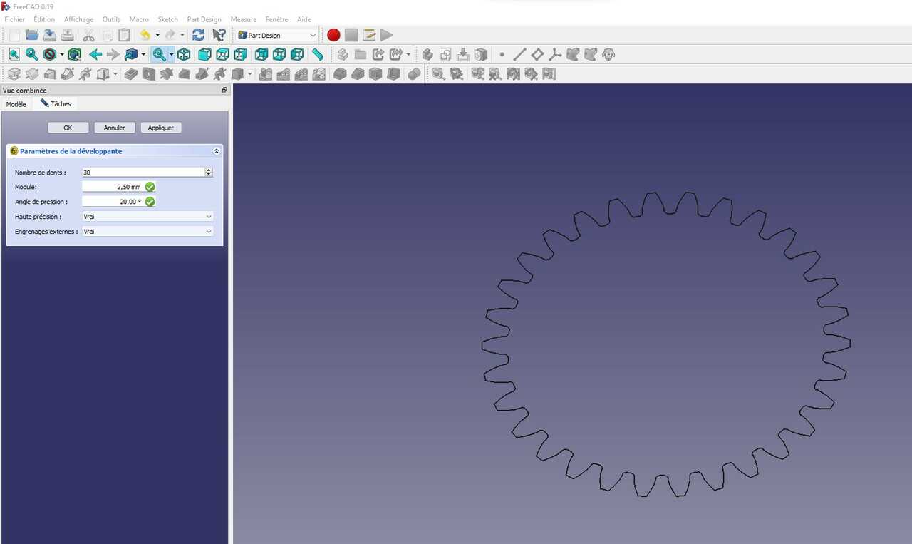
Next in the workbench you can choose the number of teeth the angle and the pitch. This will then create a sketch from which you can extrude a part.
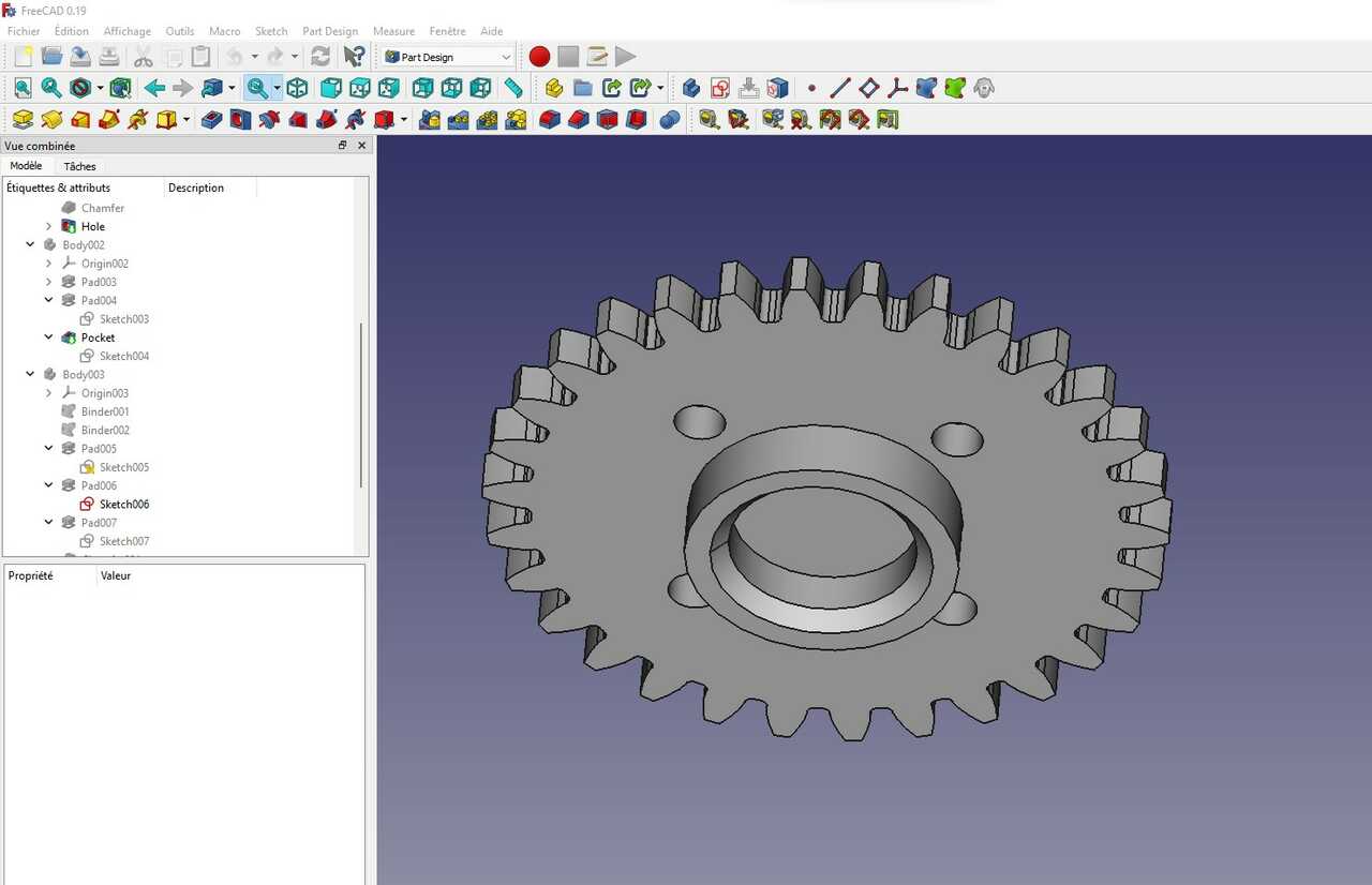
Lastly, the gears were turned into solid 3D objects and were made into STL pieces suitable for 3D printing.
Construction and assembly
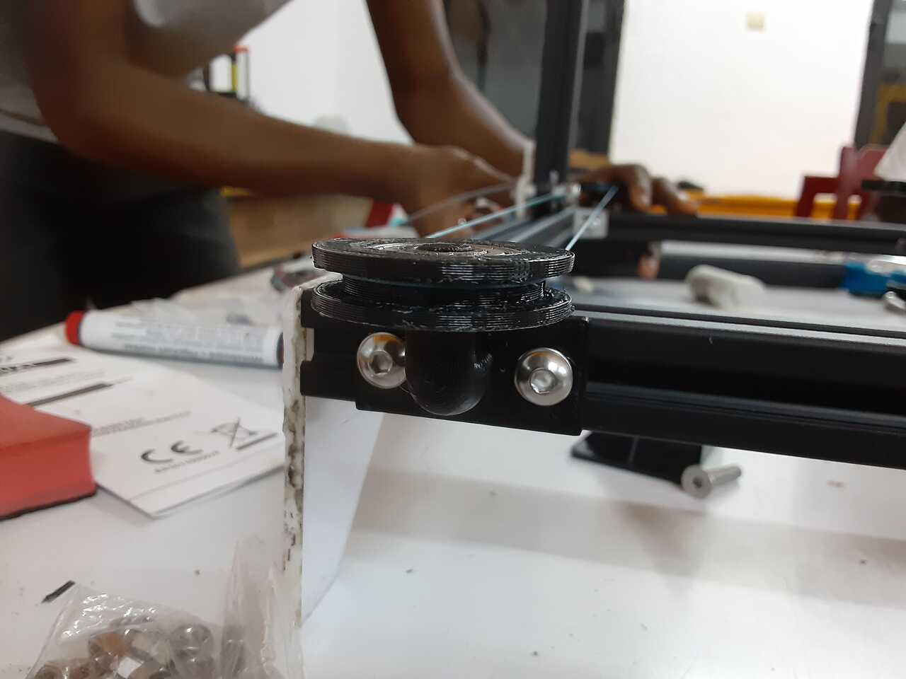
The mechanism components were 3D printed and installed on the frame. Several variations and iterations were required to get all of the components right, such as resizing the pulleys and redisgning to account for motor shafts.
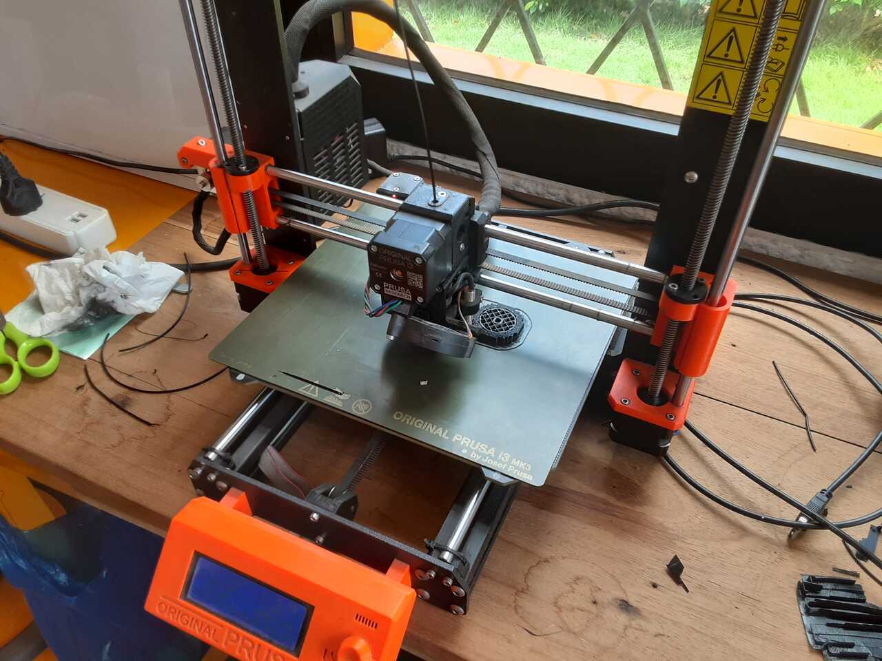
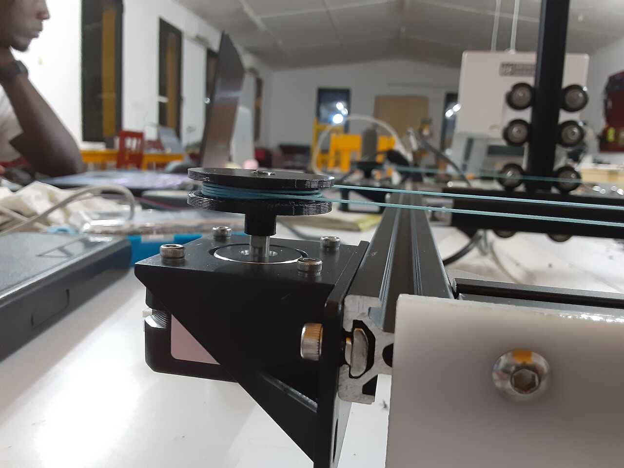
After the components were 3D printed and laser cut and finally mounted onto the frame, the next step was to test that the mechanism worked by manually moving it.
After several failed attempts at getting the pulley to work properly we realised that at the end without the motor only 1 wrap is needed whereas at the end with the motor many wraps are needed to avoid slippage.
Electronics
In this section we will discuss how the electronics were designed, including what development boards we used as well as sourcing of some of the harder components to buy off the shelf in West Africa.
A note on Frugal Innovation
It is the belief of the members of this lab that FabLabs and distributed manufacturing are the future of Africa. Just as Africa skipped land line telephones and went straight to cell phones, it is our belief that it will skip centralized manufacturing and develop straight into decentralized (FabLab) manufacturing.
That said, although FabLabs are the easiest and most accessible forms of local manufacturing availalbe, there exist many challenges that need to be overcome. ONE BIG CHALLENGE IS THE SOURCING OF PARTS. Getting parts here (especially in West Africa, less so in South and East Africa), is extremely difficult and challenging due to a critical lack of infrastructure. Enter Frugal Innovation.
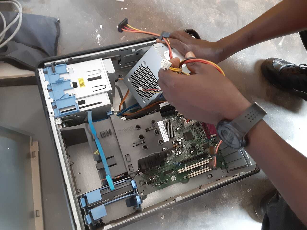
The main tenent of Frugal Innovation is design for reduction in cost and parts and more importantly, parts that can be acquired locally from existing appliances that are at end of life. This includes examples such as, repurposing old computer components, using old car or motorcycle parts, or generally salvaging any usefull electronic component. In our projects we try to incorporate this spirit in some manner and this project is no exception.
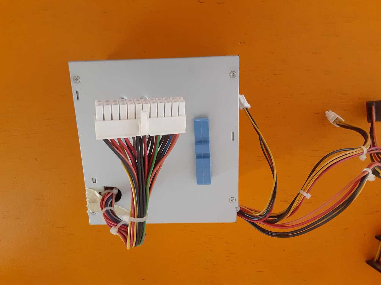
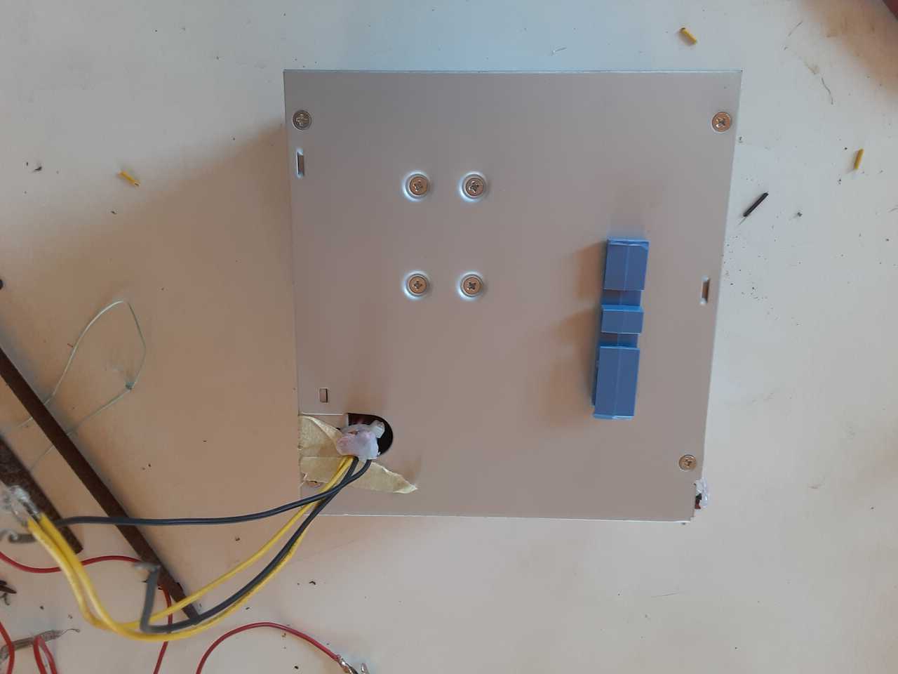
For this project we ended up repurposing an old computer power supply for our power source (below),
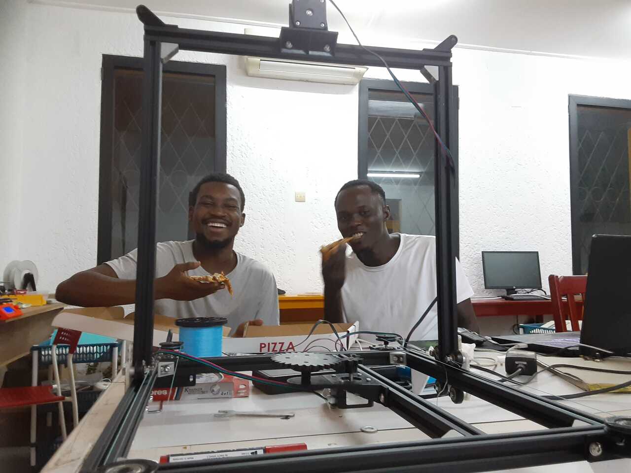
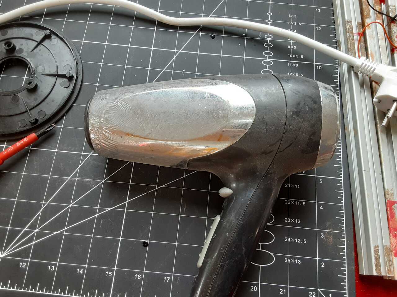
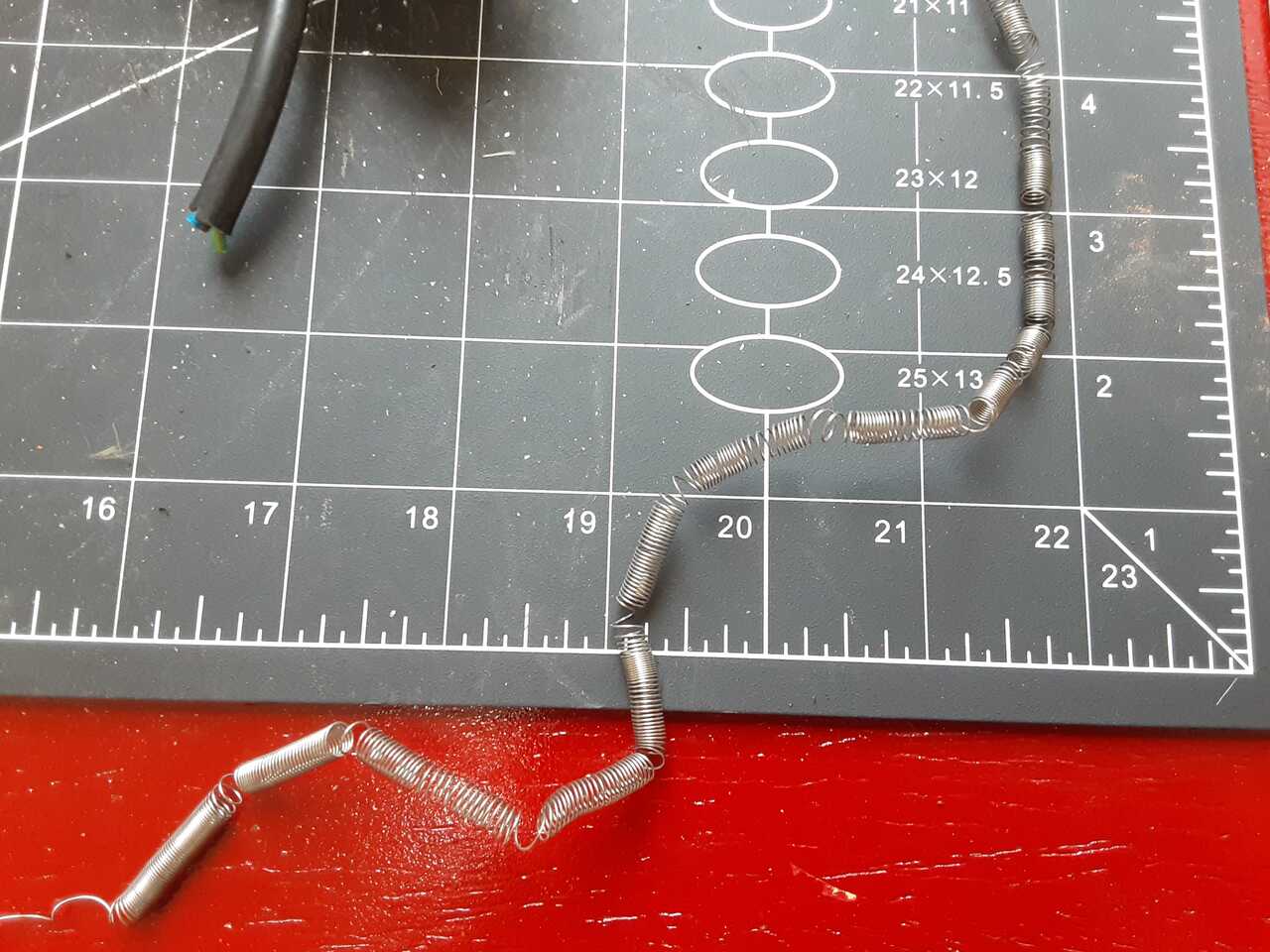
and we also recovered the heating filament from an old blow dryer for the heating wire (below).
Wiring
THe next phase in the process was wiring all the motors to the Arduino CNC shield and running it over to the box. This included wiring up the power supply. Images to come.
The next topic of discussion is the programming.
Programming
For this project we used GRBL and the universal gcode sender platform. Since the 3rd axis is rotational rather than translational it presents some additional little tricks that are needed to program a grbl code if you want to be able to cut a 3D object (not just a 2D one like an aerofoil).
Our methodology was based off of the instructions shown in the youtube video below. Discussion regarding the programming at timestamp 15:08 in the video.
Calibrating the machine
As shown in the video we started by calibrating the machine to suit the new driving mechanims. This is done by connecting the machine to UGC and selecting “Machine > Setup Wizard”. You can set the direction of the axes on the first page, and on the next page you can use the calculator to move the machine in one axis, enter the measured amount it moved (using a ruler), and it will provide you with a new estimated step/mm value.

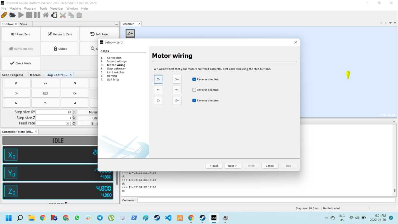
The photos below display the setup and the final values of the step/mm values. The z was calibrated slightly differently. As we are aiming for a rotation we aimed to make 1 mm = 10 degrees of rotation of the table. So we set the controller to jog 9 mm in the z axis (90 degrees) and manually changed the value until a 9mm jog corresponded to a 90 degree turn.

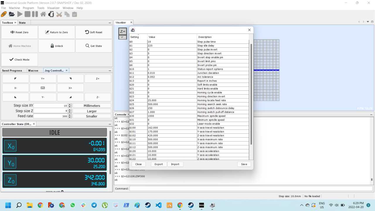
In the end the paramaters for step/mm in each axis were as follows:
- x-axis: 162 step/mm
- y-axis: 175 step/mm
- z-axis: 550 step/mm
In the next section we will talk about how to generate the g-code using inkscape and further how to use the z-step size and cut-depth dimensions to represent one rotation.