11. Output devices
Group assignment:
- Measure the power consumption of an output device
- Document your work to the group work page and reflect on your individual page what you learned
Individual assignment:
- Add an output device to a microcontroller board you’ve designed and program it to do something
Have you answered these questions?
- Linked to the group assignment page
- Documented how you determined power consumption of an output device with your group
- Documented what you learned from interfacing output device(s) to microcontroller and controlling the device(s)
- Described your design and fabrication process or linked to previous examples.
- Explained the programming process/es you used.
- Outlined problems and how you fixed them
- Included original design files and code
- Included a ‘hero shot/video’ of your board
Group assignment
For the group assignment we measure the current of a stepper motor using a bipolar steper motor, just with the lab power supply
To measure any device current consumption we can use a multimeter that needs to be connected in series to the output device, to calculate the power consumption of the device we can multiply the voltage with the current and that will make an estimate value.
P = V.I = 9v. 0.2A= 1.8W
Designing the microcontroller board
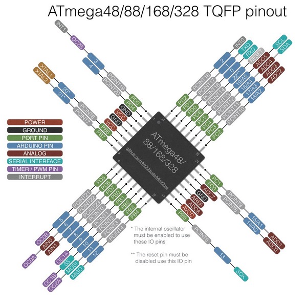
In order to make progress in my final project I decided it was time to start developing the motherboard, since the microprocessor compatible with cnc Systems we have available at our lab is the Atmega 328P I decided to go that way.
Research
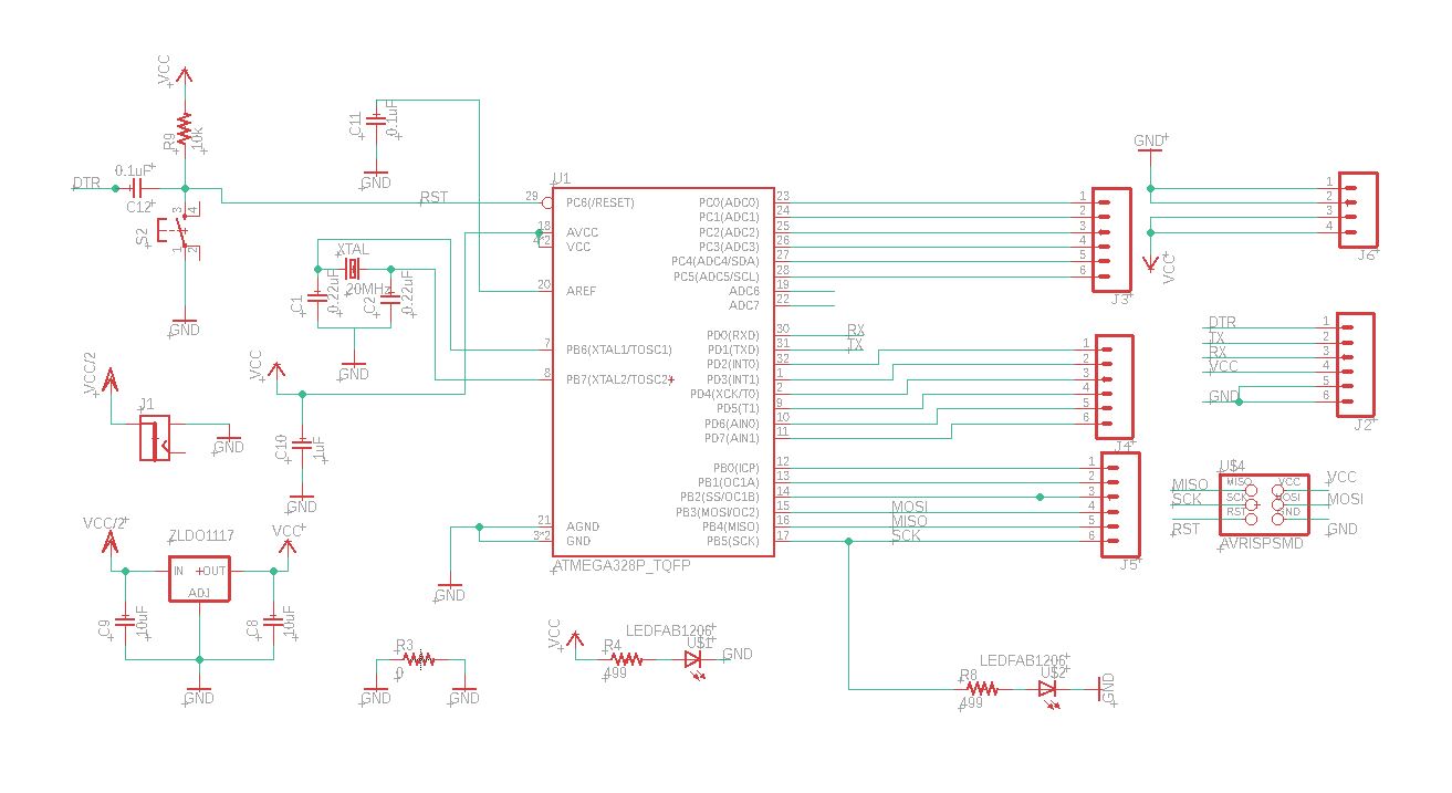
After looking at different boards from other fab academy studens, I took my instructor`s advice and did a general purpose board for this week, they did one in 2019 at tecsup, So I used the same schematic as his to build my board, since the project I have to make is quite similar to his machine week project.
Abdon Rotela`s Machine design page
Files
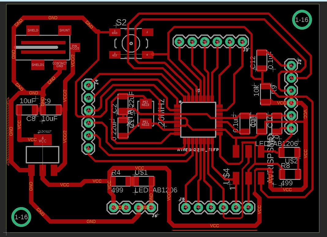
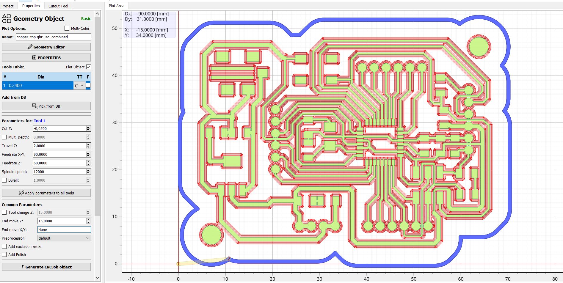
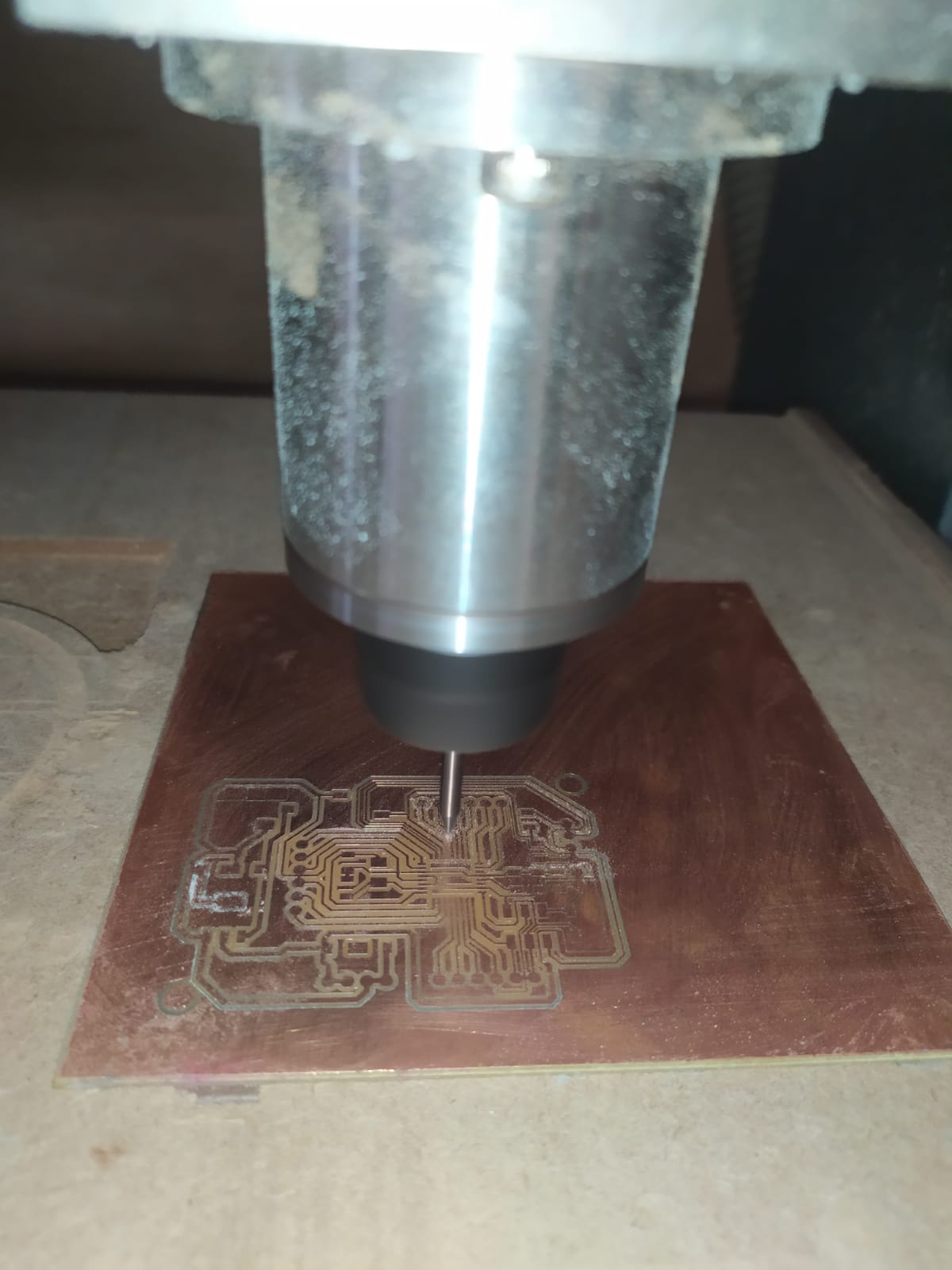
For the main route I used a 0.24mm bit with 4 passes, at 90 mm/min and 12000 RPM of the spindle, using the roland MX540 software.
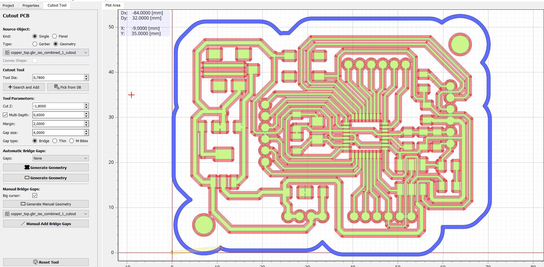
For the cutout I used a 1/32 inch bit at 7000 RPM of the spindle, and also 90 mm/min X and Y feedrates.
To generate the geometry, first I made a thicker referential geometry, just to make an offset of the main board and to have some space.
after that I used that geometry as a reference to make the cutout path. using the generate geometry tool.
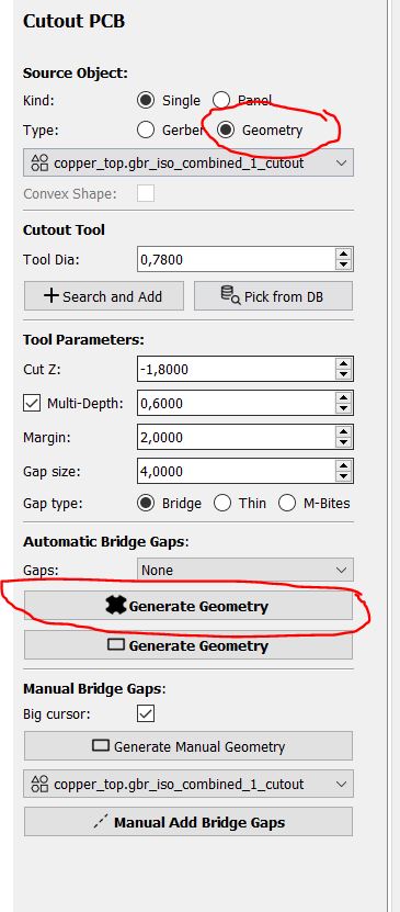
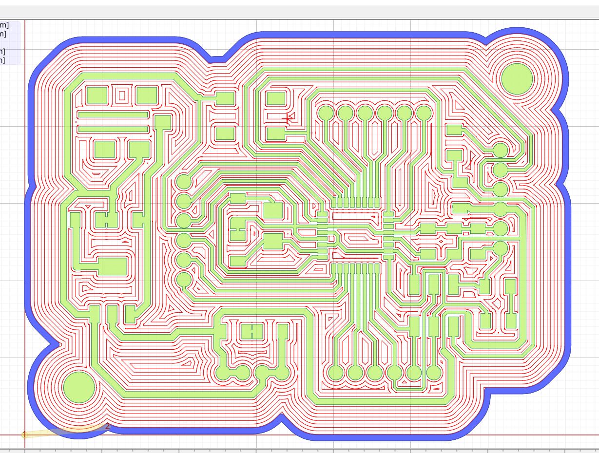
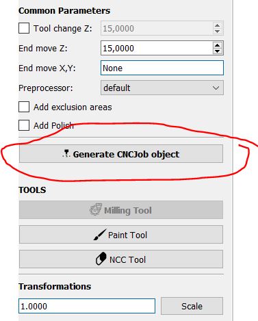
after creating the geometry I was able to create the CNC object and path to send to the Milling machine.
Some of the problems I had was that the milling surface was not perfectly flat, that made me repeat the process a second time lowering the bit 0.05mm more
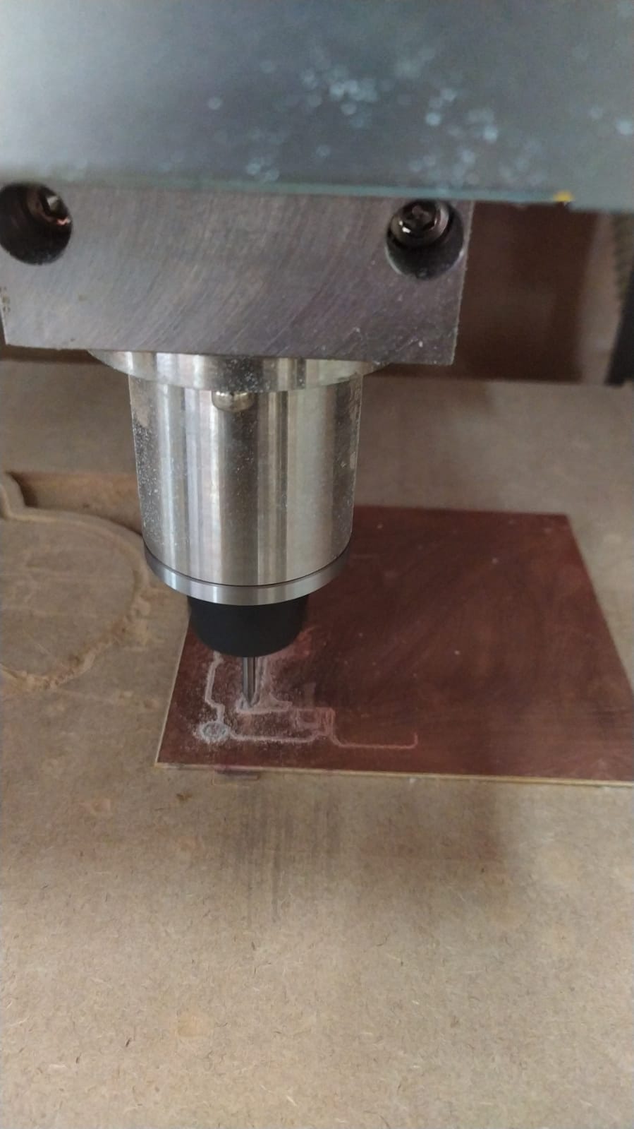
after that, the pendrive I was using during the milling machine job was removed during the process, the milling stopped but no harm was made, all I had to do was to start over the process.
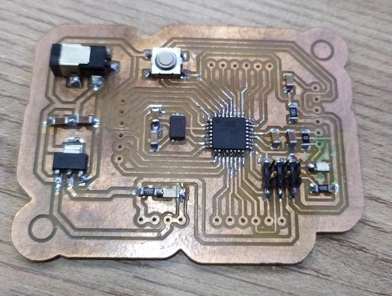
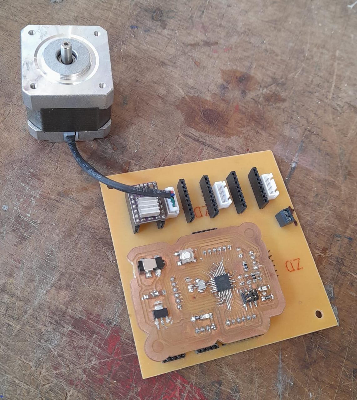
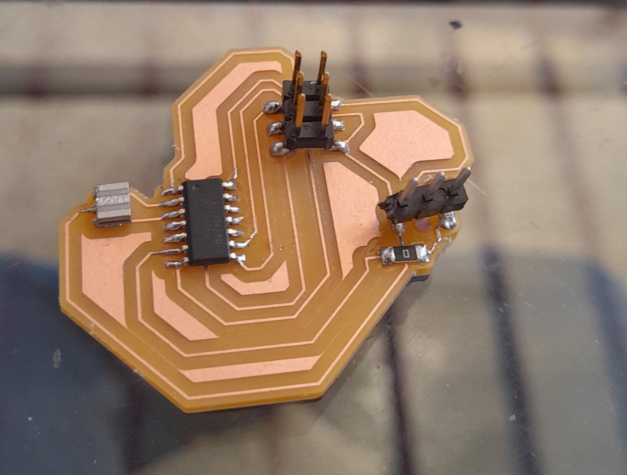
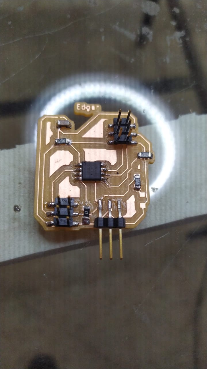
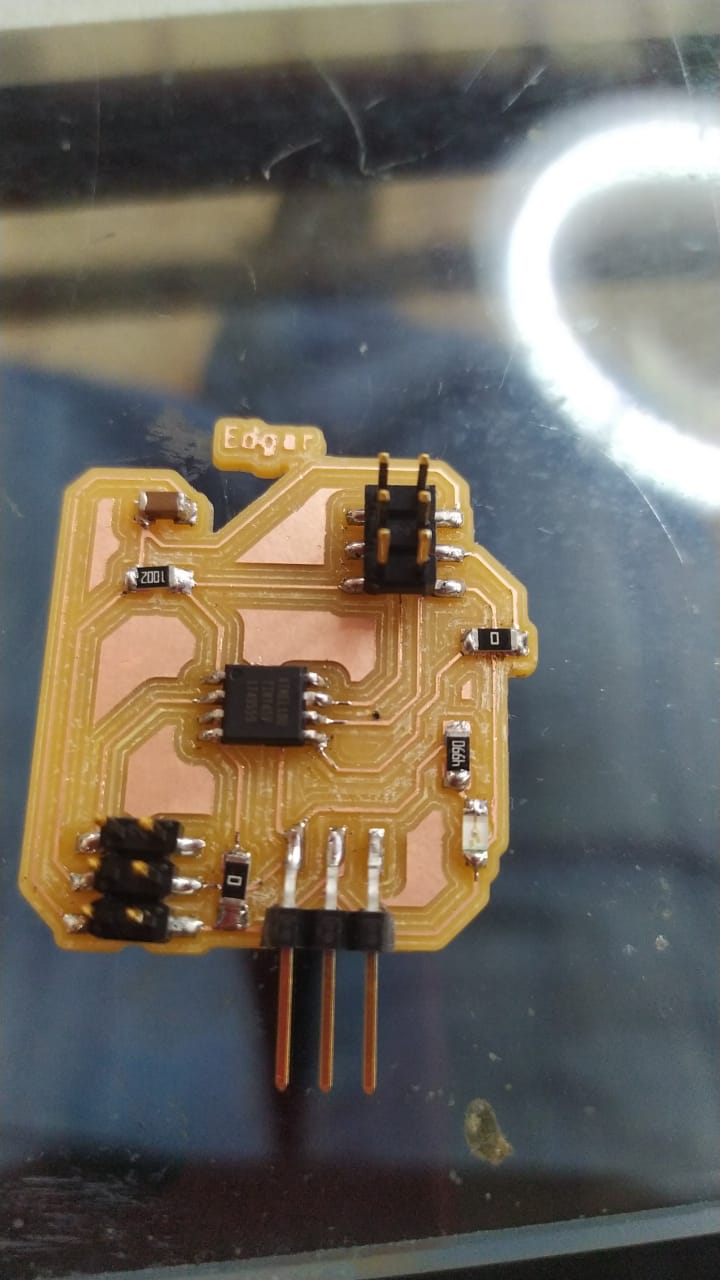
The board after soldering.
For programming I used Arduino and GRBL firmare to move a stepper motor.
To upload the GRBL firmware you can download the grbl firmware in the link below
the first step is to install the GRBL library
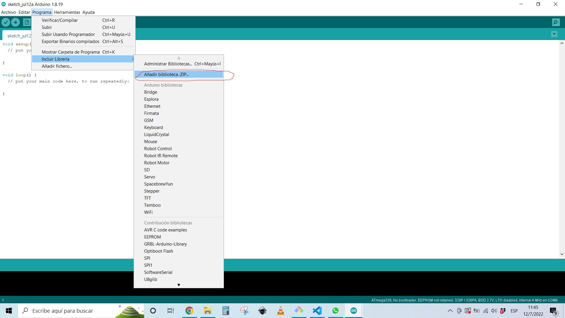
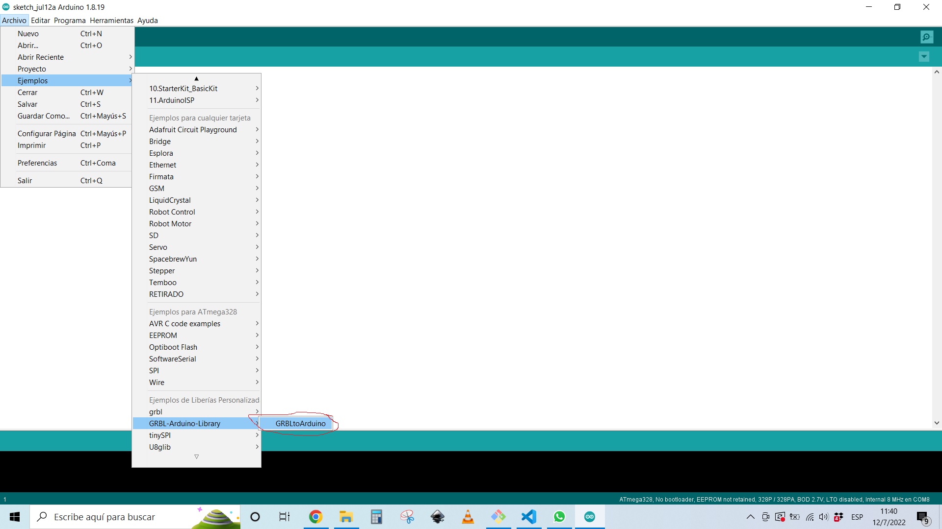
after that you should open the example libraries as shown in the following picture.
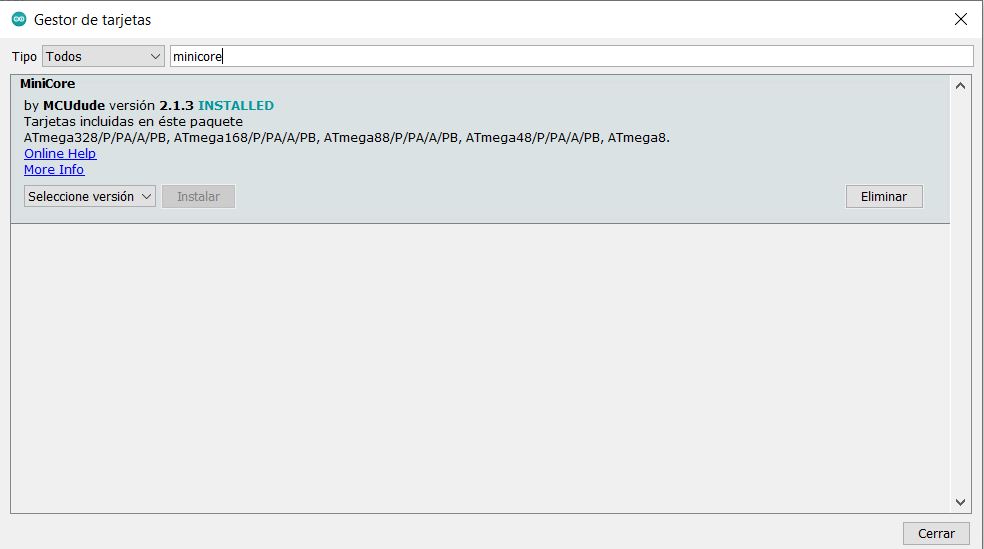
I installed minicore to be able to upload and modify clock frequency of the board in the preferences menu of arduino IDE using the following code.
https://mcudude.github.io/MiniCore/package_MCUdude_MiniCore_index.json
after that I used the board manager to install the minicore complement.
To controll the motor I used a DRV8825 Stepper driver and the cnc Shield made by my classmate - Jorge, modifying a few things that needed correction, like the power connector and the drivers female connectors.
New output board
I tried to do an Attiny44 board, but didn´t put much effort into it because I was very low on time, so I ended up using more time in the end, fixing everything. So, a recommendation is to just do it right the first time.

Making everything again
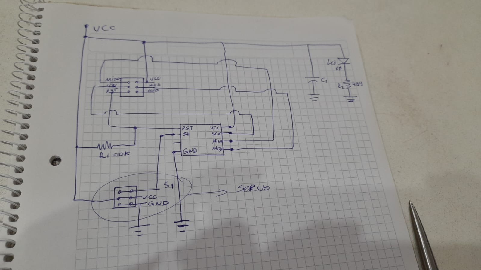
Schematic and design
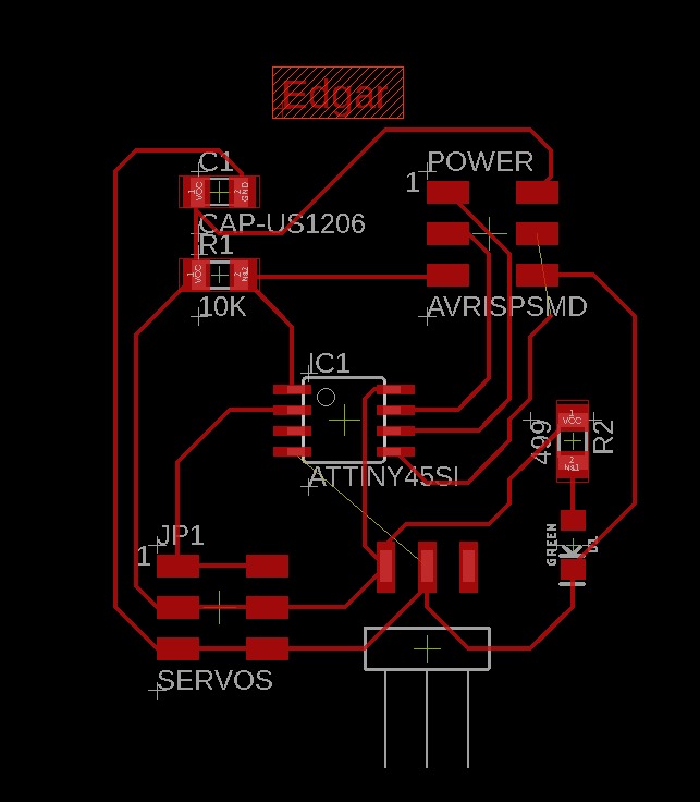
This time I choose the attiny45 as a circuit and started by making an Schematic in a notebook. I based my design on Keith´s Tan output devices week.
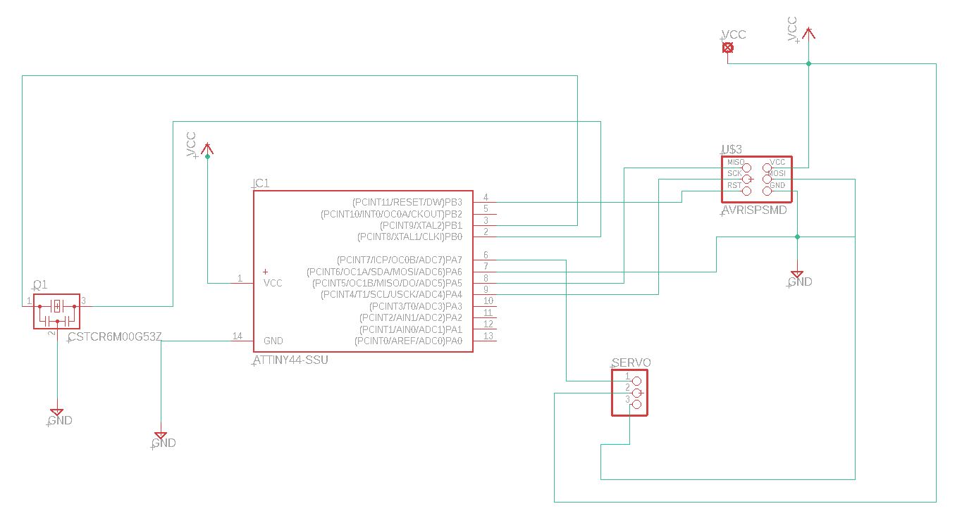
After that I created the schematic in Eagle, to modify the original design, I added a power led light, and removed the second servo, since I only planned to control 1 servo at the time.
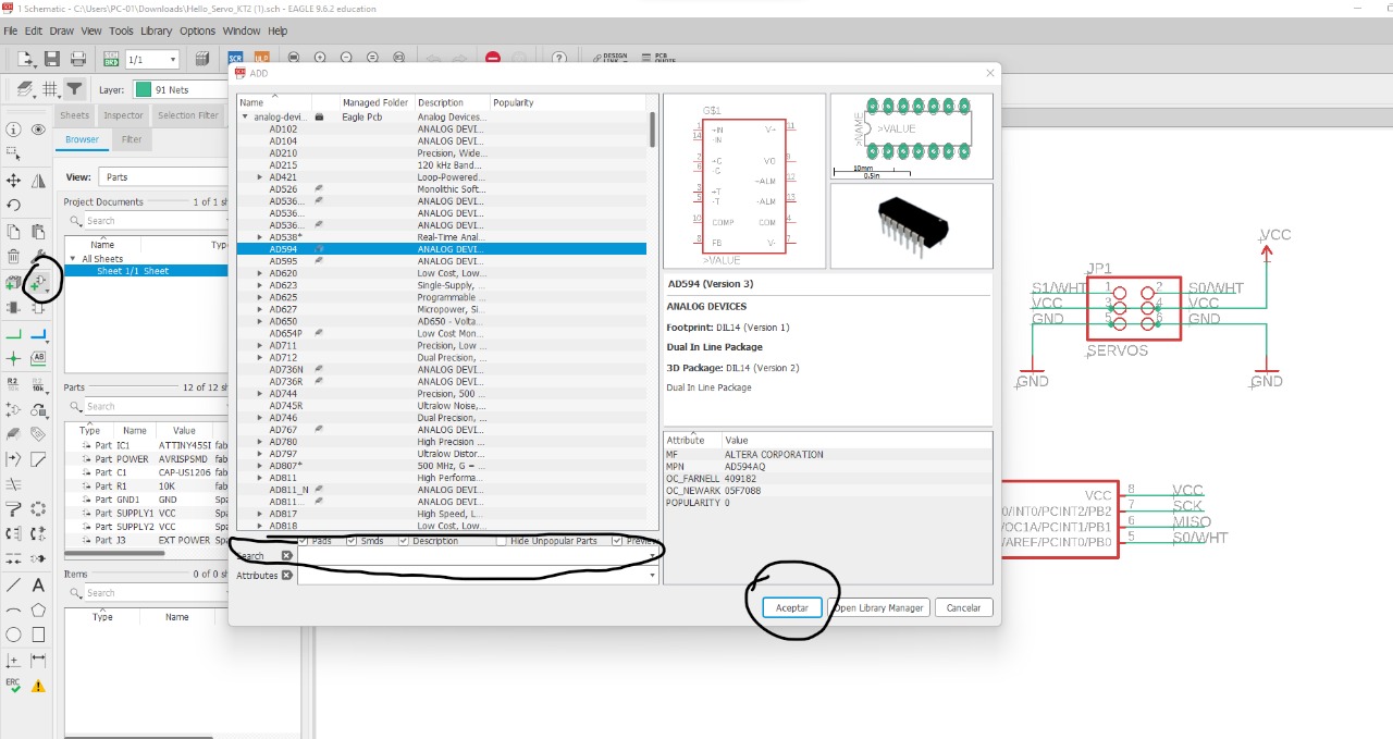
What I have realized, is that it would make my life easier to add a few 0 ohms resistors to simplify the tracks of my circuit.
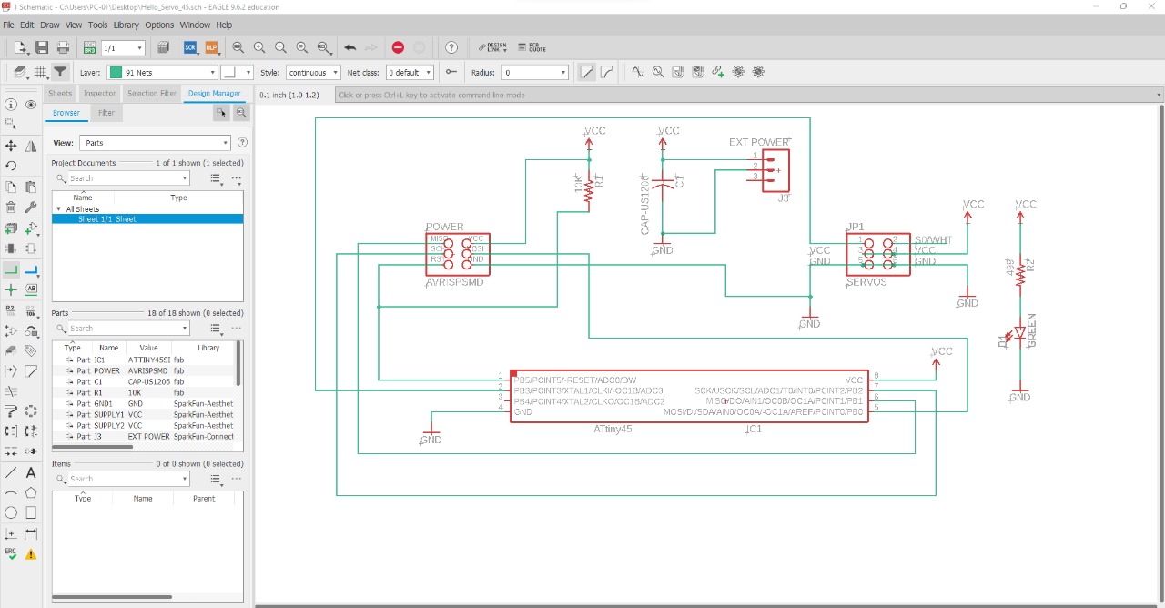
So I added both shown in the next picture.
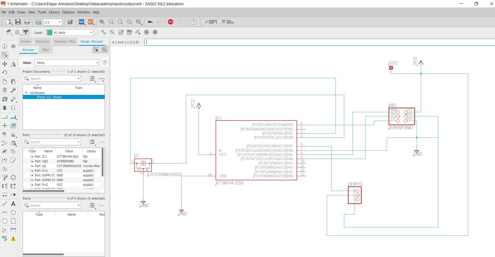
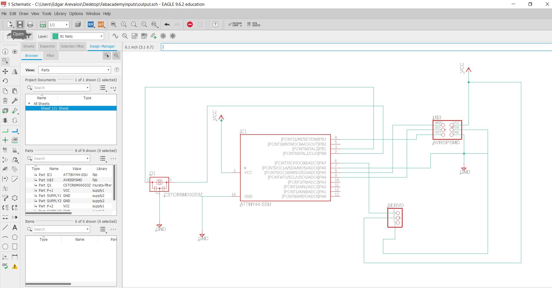
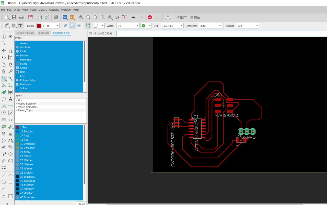
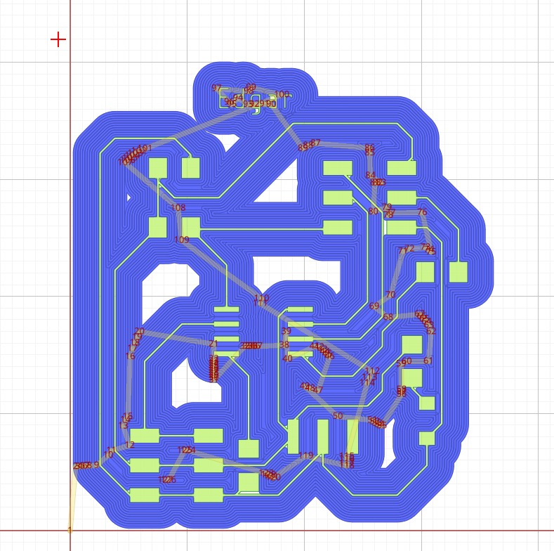
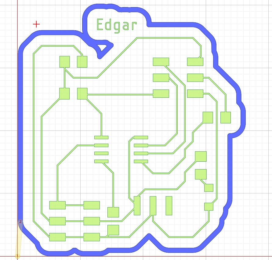
Eagle Routing
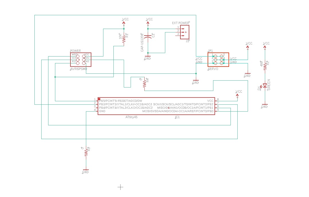
First I did route as I could and then realized where the 0 ohm resistors would go.
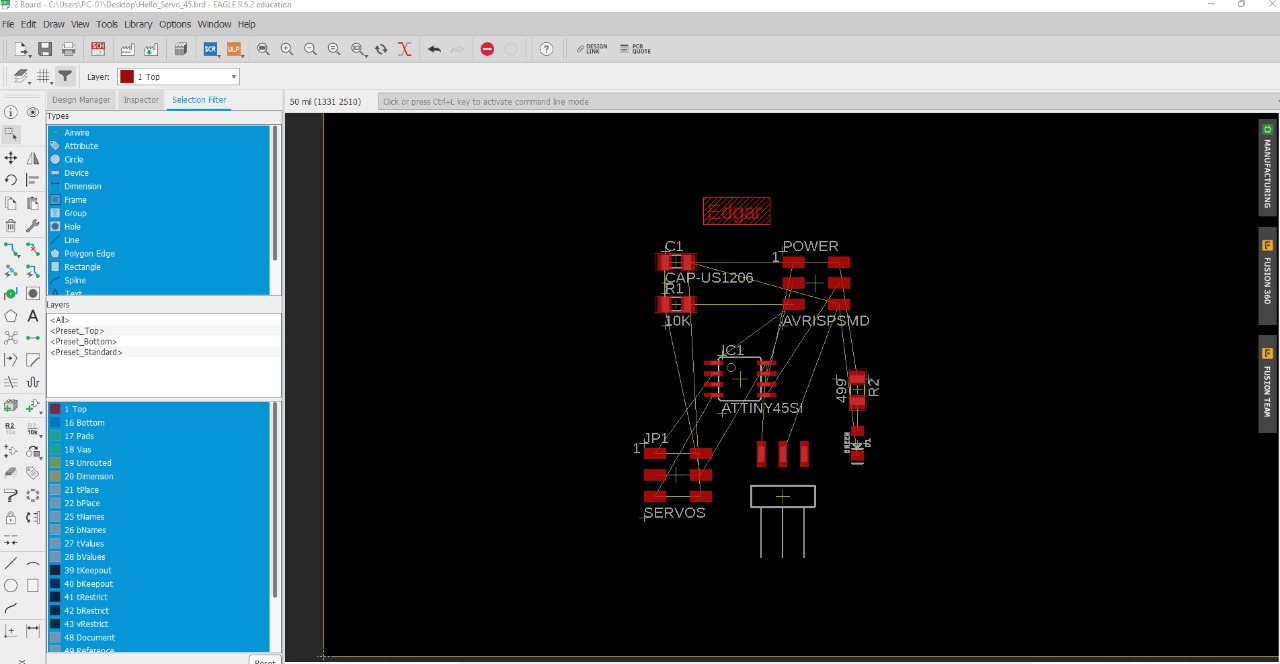
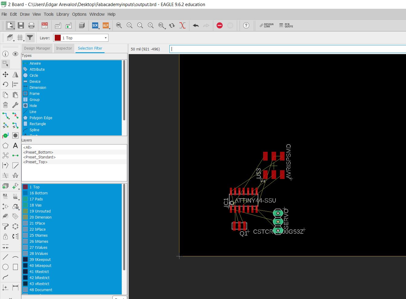
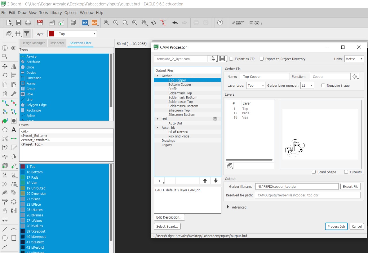
After finishing routing I exported the files as a Gerber file to open it in flatcam.
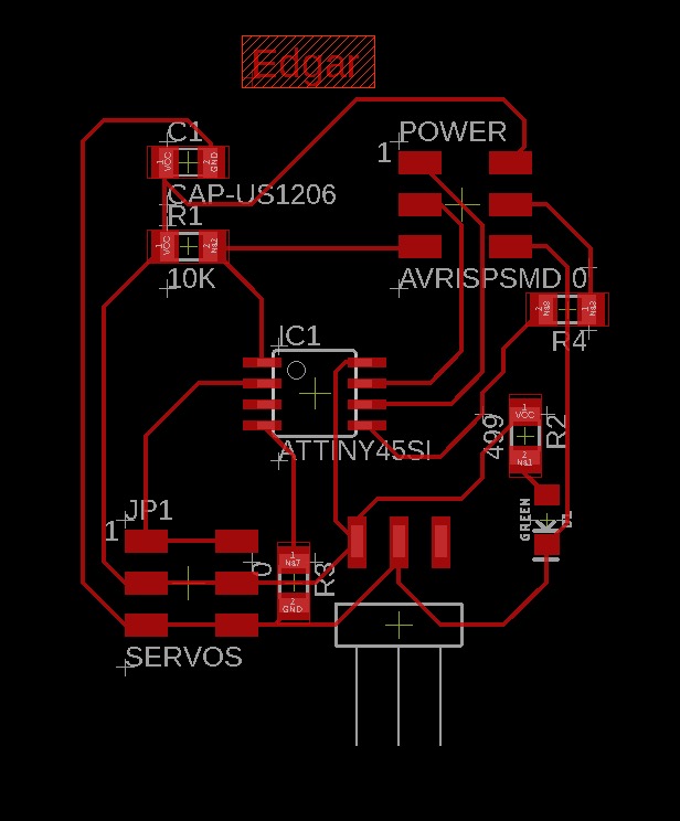
In here you can see where the 0 ohm resistors R3 y R4 where putted.
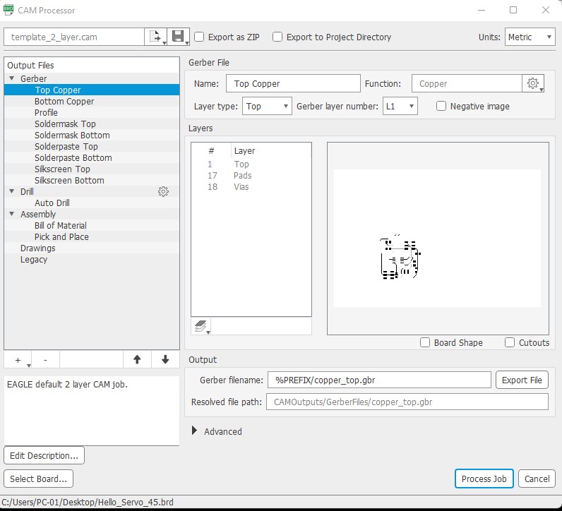
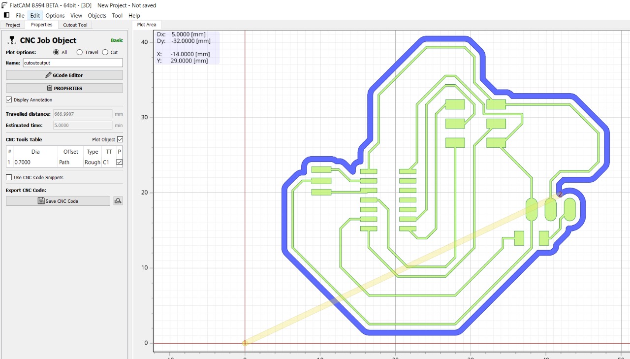
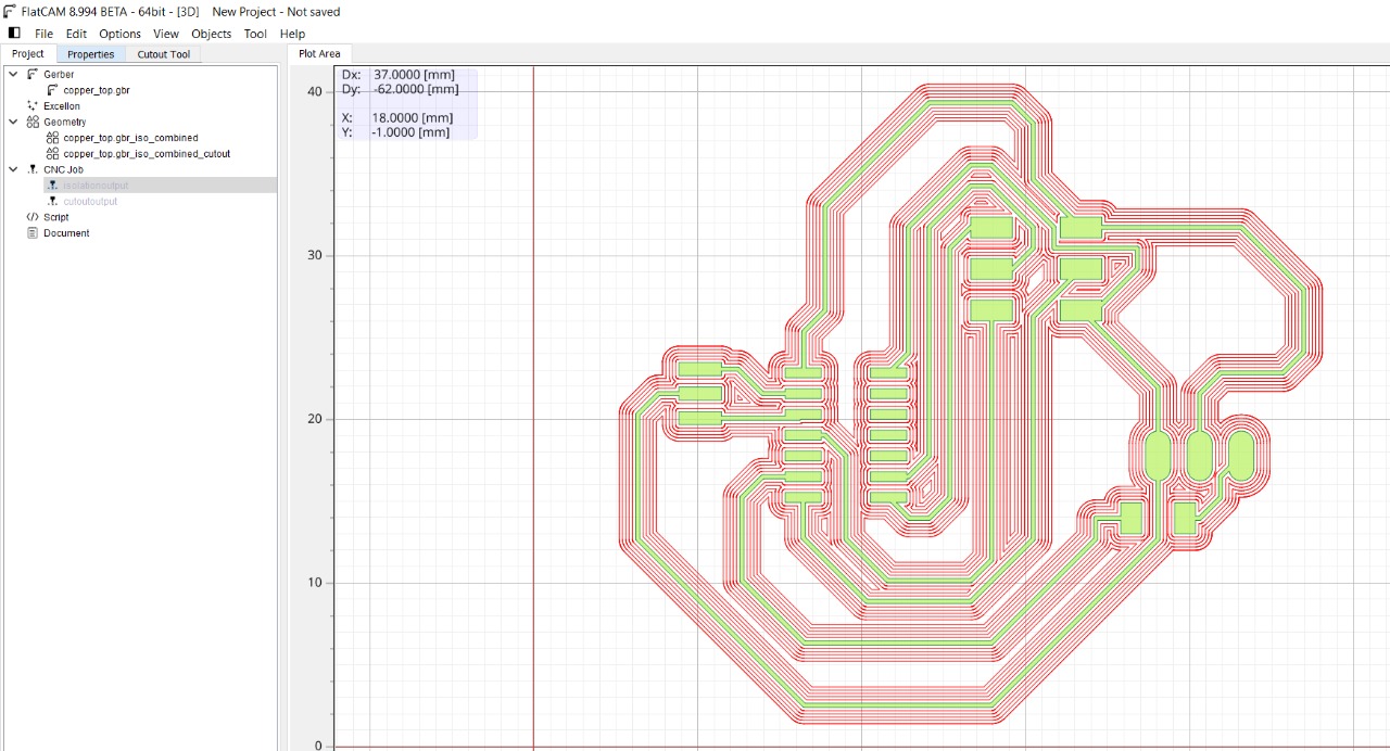
In flatcam I created the gcode files, I used a 1/64 inch router bit for the isolation routing operation.
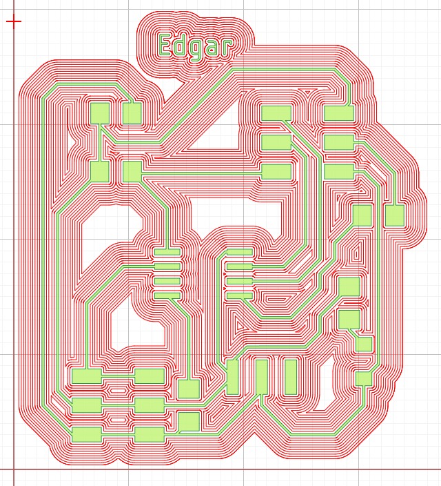
and then I used a 1/32 inch bit for the external cutting of the board.
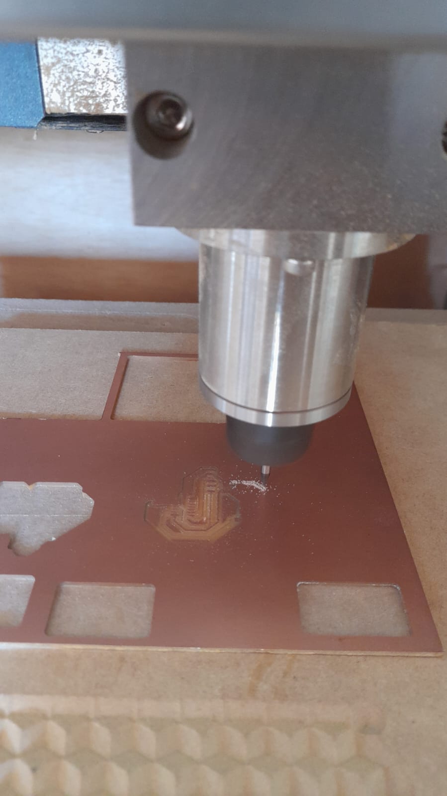
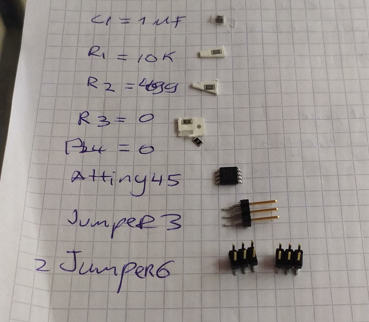
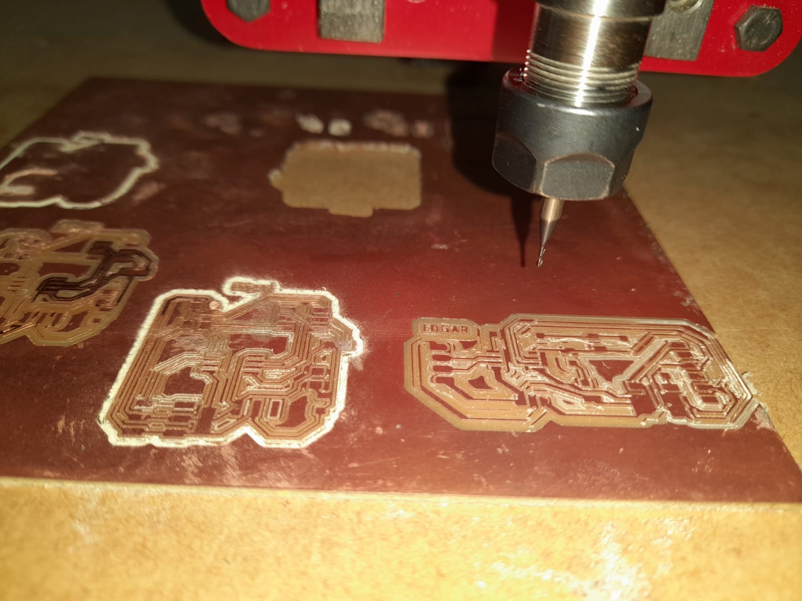
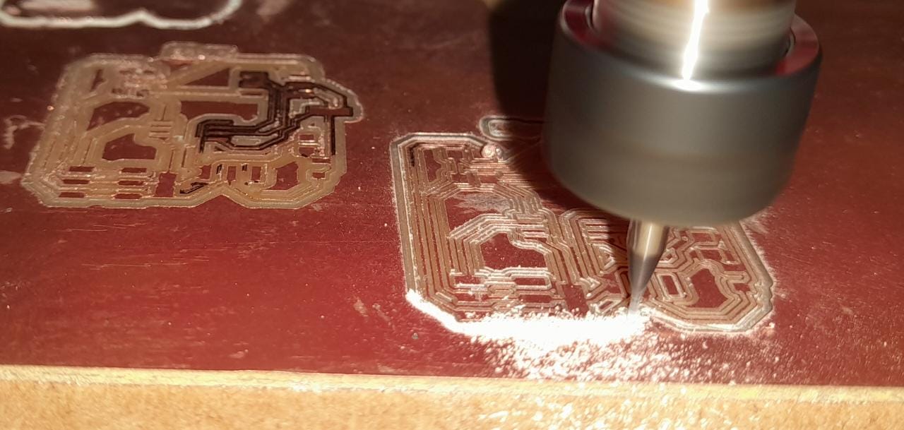
Components and board Machining, Soldering.
I collected all the components from the lab and soldered them into the board
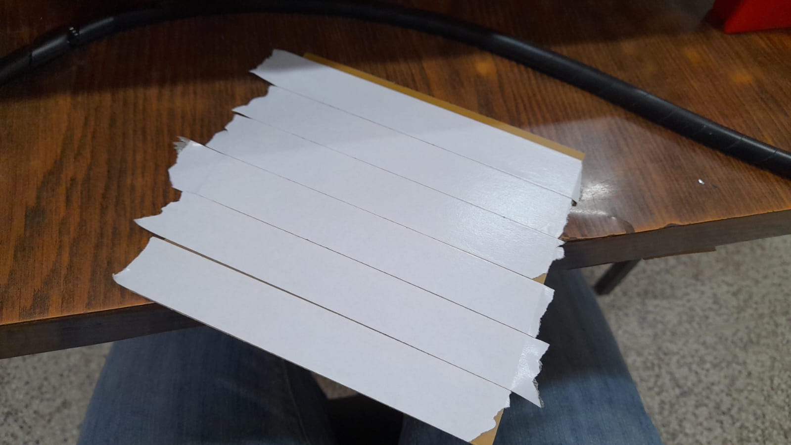
putted some double sided tape to fixture the Copper board into the base of the CNC machine.
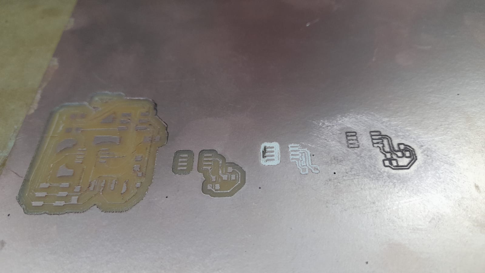
In this excercise I used my final project as the routing machine, I made some test to try the tolerance of the machine, but then I realized I putted the router bit to far away from the collet and that made the bit vibrate more.
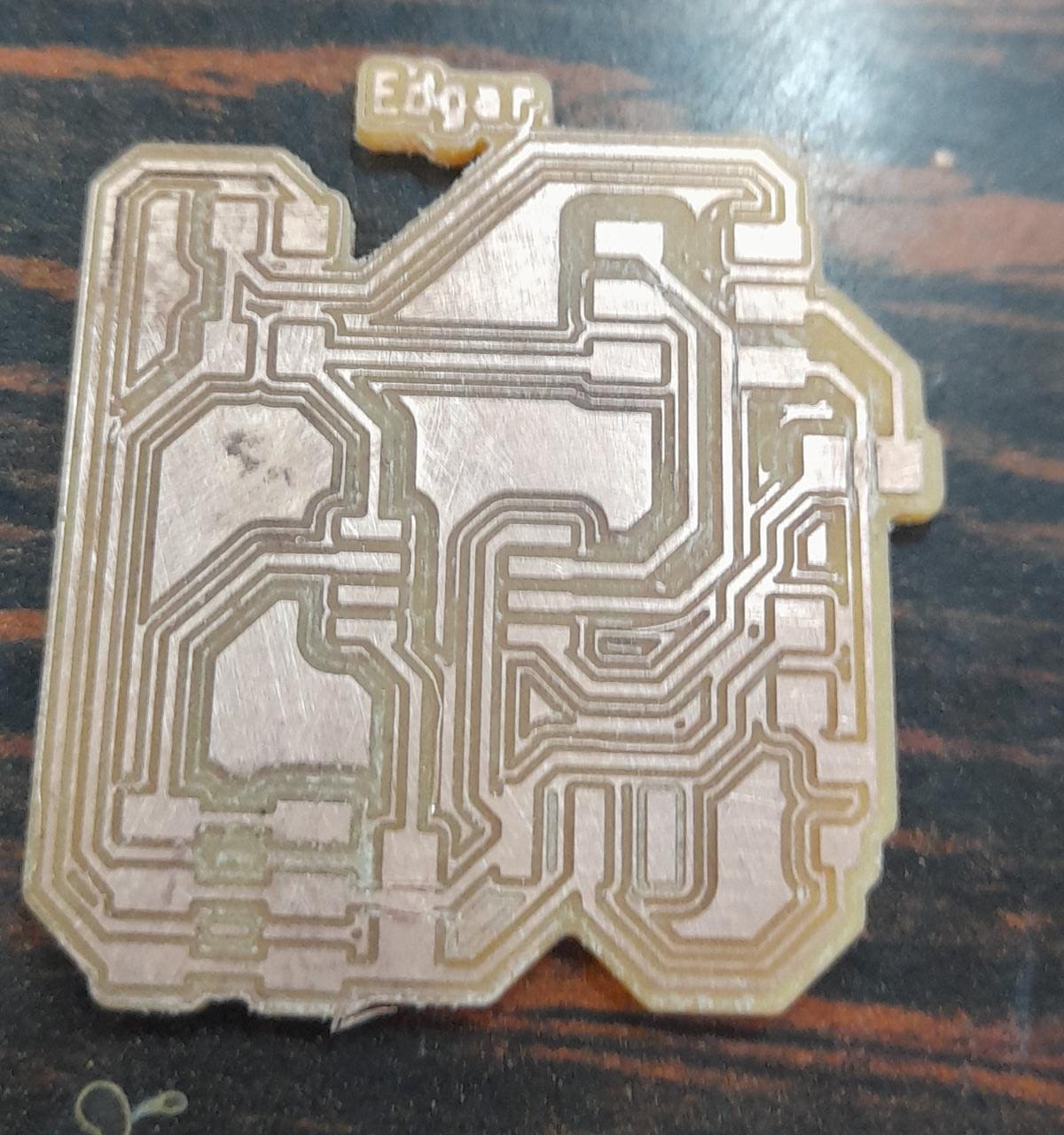
finally I´ve got some pretty good results and started haunting for components for my board.
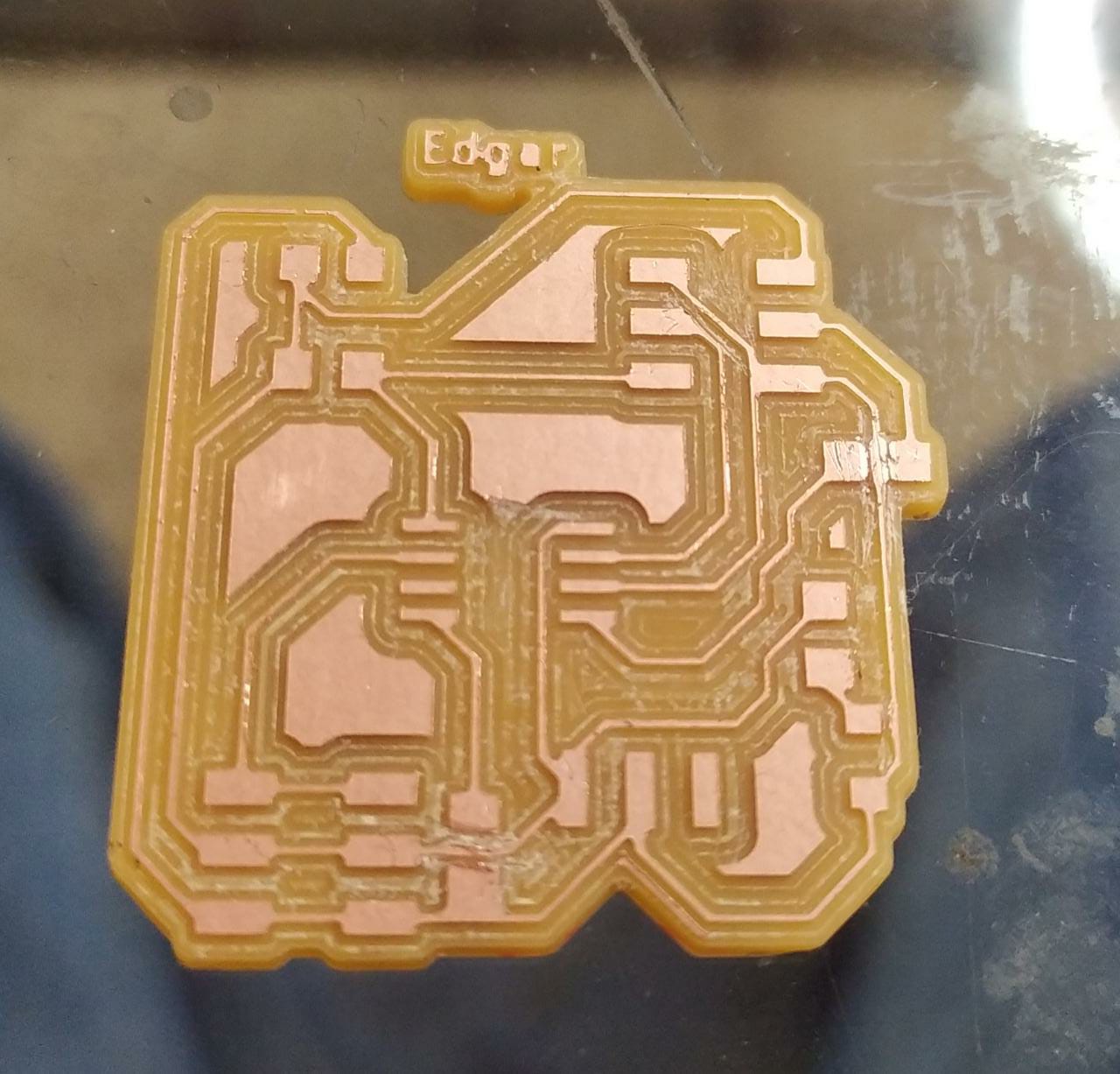
I soldered everything and didn´t realized one part of the routed copper had a short circuit, so it didn´t work.
I forgot to put up the temperature in my soldering heat gun, it was only in 100 degrees so I accidentally broke my board again.
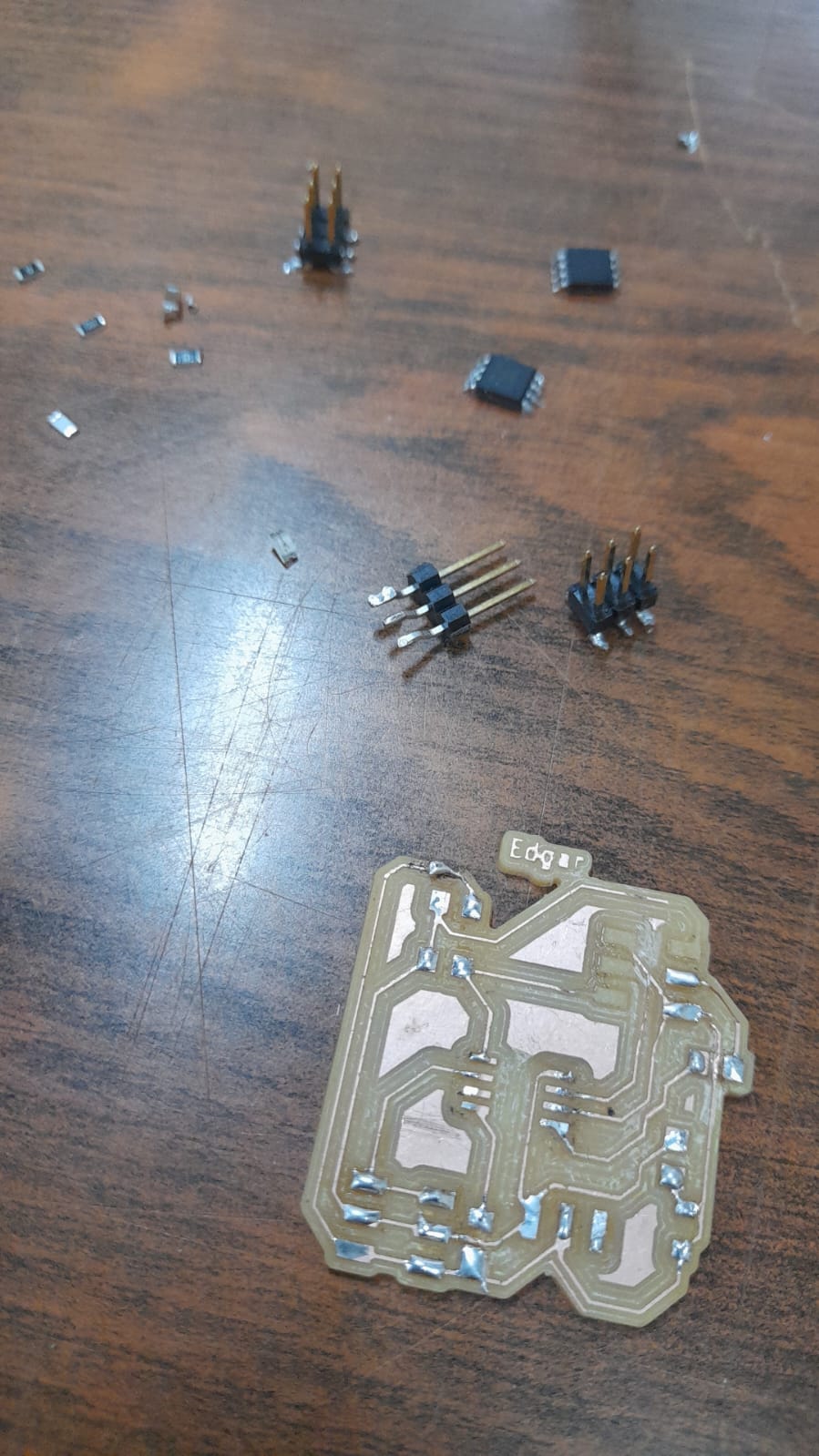
I dissasembled everything and started over again.
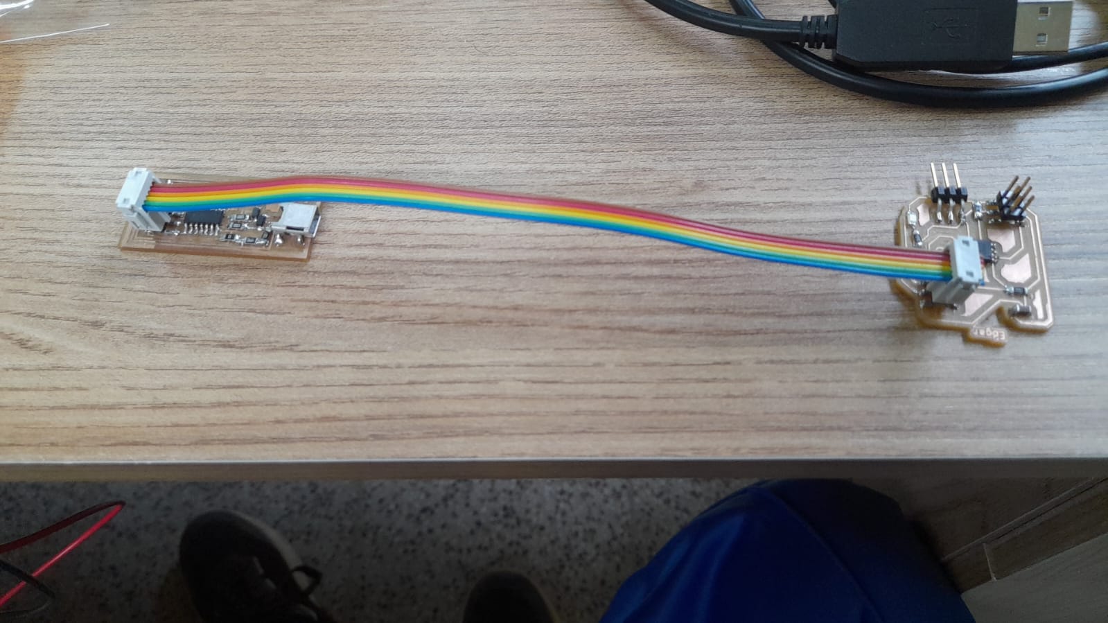
This time the board came out much better and I checked everything before soldering.
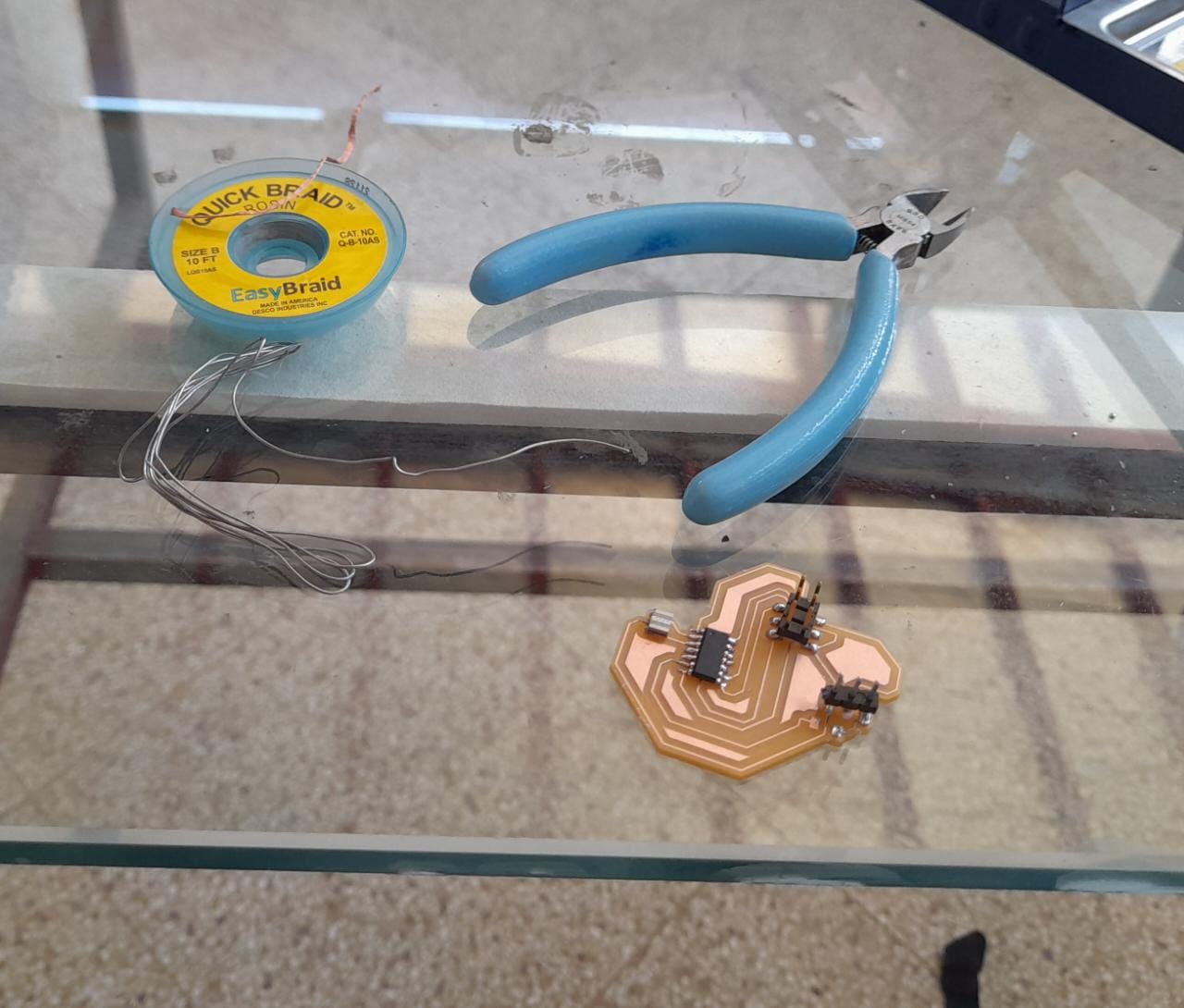
Programming
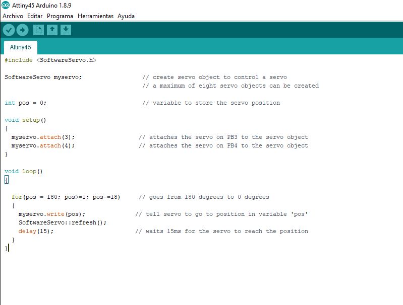
I used my attiny UBBtiny programmer and arduino IDE to program the board to move a Servo from 180 degrees to 0 degrees in steps of 18 degrees.
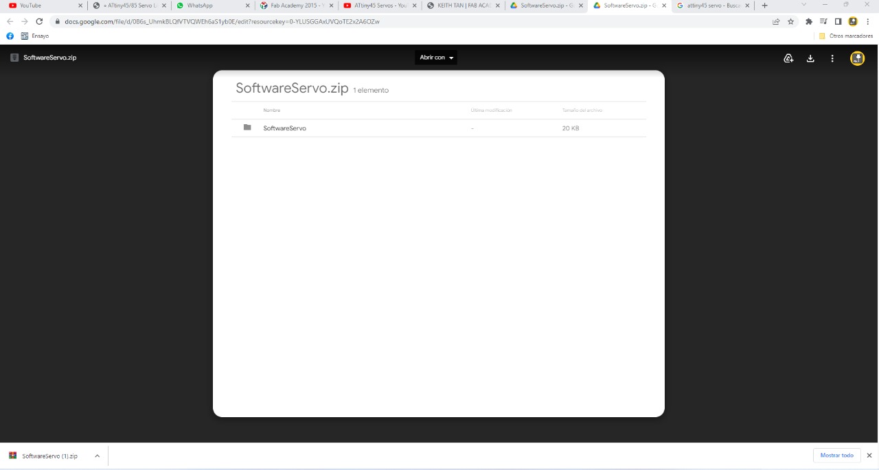
I had to install a library called SoftwareServo that you can download it down bellow the page. This library is prepared to move a servo with 8Mhz internal clock of the Attiny45
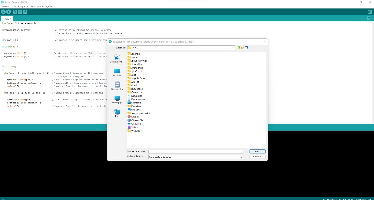
I used the following code to move the servo.