5. Electronics production
What should I learn this week?
Group assignment
- Characterize the design rules for your PCB production process: document feeds, speeds, plunge rate, depth of cut (traces and outline) and tooling.
- document your work (in a group or individually)
Individual assignment
- Make an in-circuit programmer by milling and stuffing the PCB, test it,
- then optionally try other PCB fabrication process.
Learning outcomes
- Described the process of milling, stuffing, de-bugging and programming
- Demonstrate correct workflows and identify areas for improvement if required
Have you?
- Linked to the group assignment page
- Documented how you made (mill, stuff, solder) the board
- Documented that your board is functional
- Explained any problems and how you fixed them
- Included a ‘hero shot’ of your board
Summary
This week I finally got free of some work related issues on Saturday, so I decided to start the week by planning my work, and decided that this is priority number 1. Because the previous weeks I got behind in documentation.
Electronics production TimeTable.
Sunday to Wednesday Program
| Sunday | Monday | Tuesday | Wednesday |
|---|---|---|---|
| Markdown studying and writing a final project page | PCB milling and soldering of the ISP programmer | Documentation, and improving documentation skills | Classes and preparing timetable for next week. |
Group´s Assignment
In the group Assignment we learned all about our lab CNC mill, The roland MDX 540, allso we learned how to characterize the machine and the CNC bits of 1/32 inches and 1/64 inches.
You can access our work on the link below.
Flatcam Installation
For the installation of the software we followed a tutorial provided by one of our Lab instructors.
I installed Flatcam with not much trouble. here is a link to the official website:
Flatcam: Setting up a project and importing the file.
First Thing I had to do was to select a programmer from the fab academy page according to the materials we had in the lab.
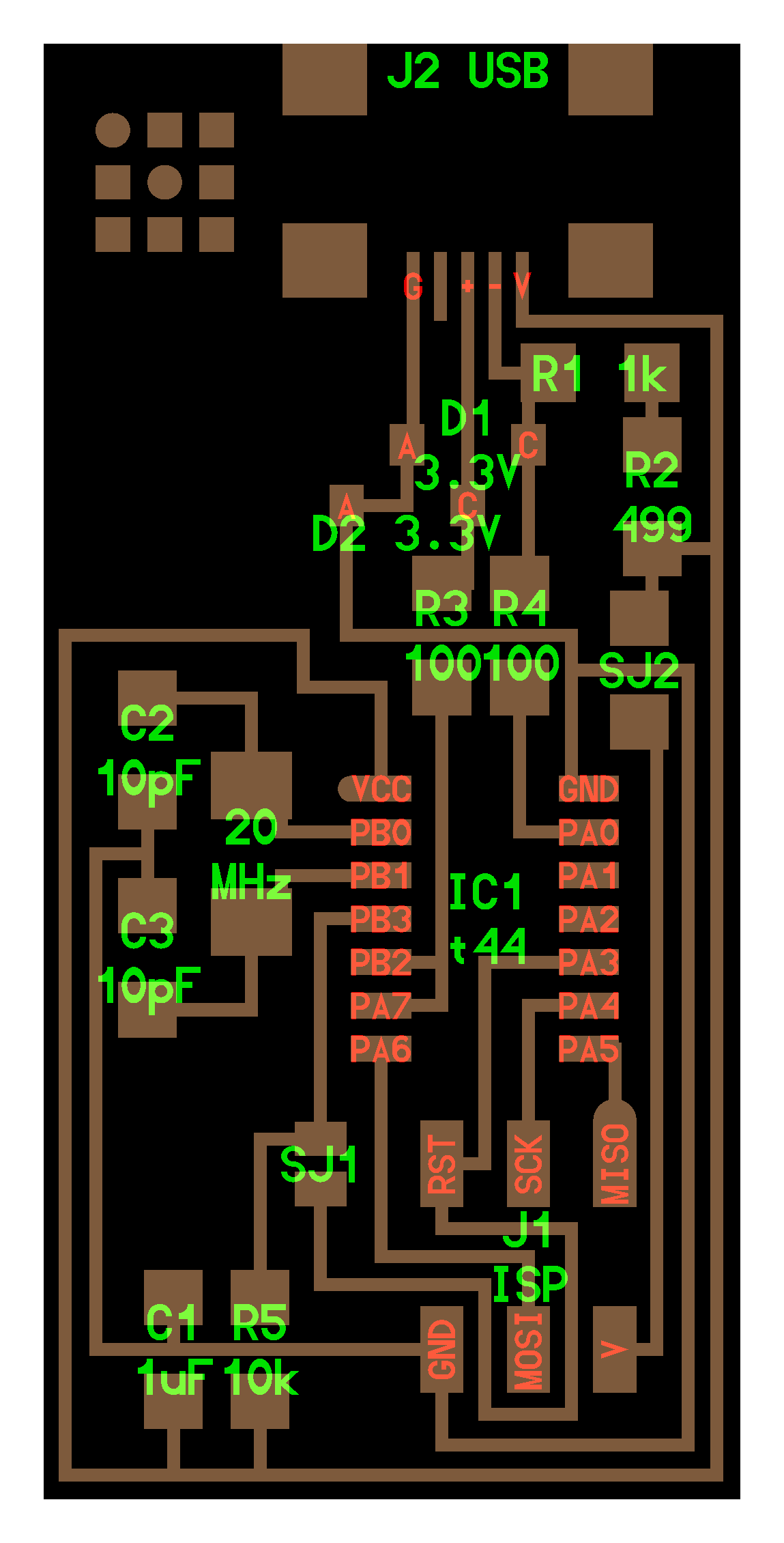
After that I had to import the hello world ISP file on png format from the fab academy repository
We had to upload the PNG file to flatcam of the traces, to do that we followed our instructor tutorial as well
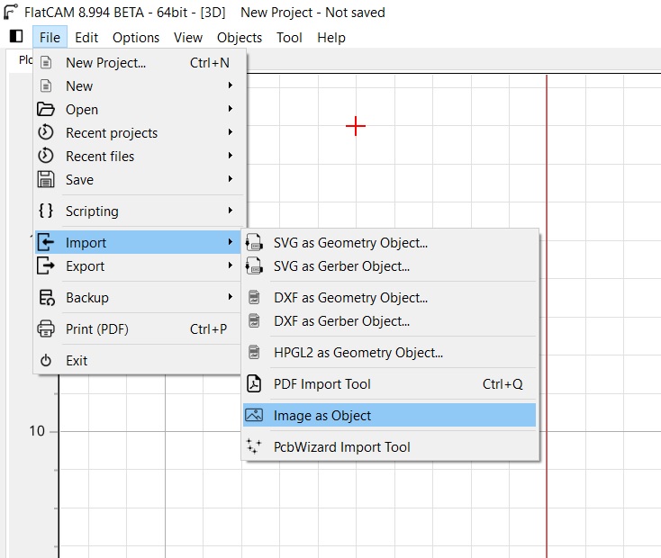
I have to choose import and image as an object.
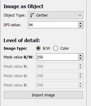
The next step is to select the proper DPI of the png image
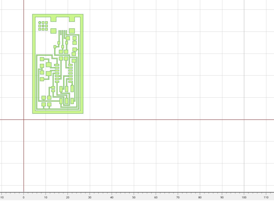
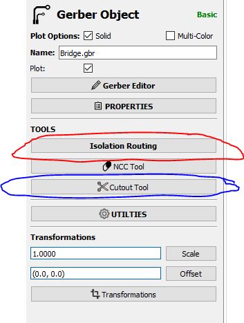
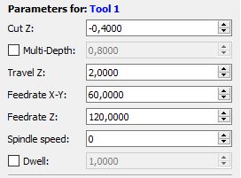
After that I had to choose isolation Routing (marked in red) and to select the proper milling bit for the job, for cutting the traces, I used a 1/64 inch endmill, and for cutting the board I used the 1/32 inch endmill with the cutout tool(marked in blue).
We used the programmer with the Atiny44A and the machine used to machine was the Rolland MDX 540
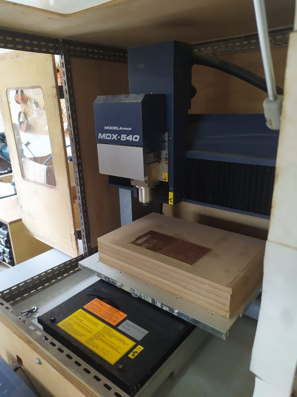
With this machine we used a 1/64 of an inch bit to route the PCB and a 1/32 of an inch bit to cut trough and obtain the final board.
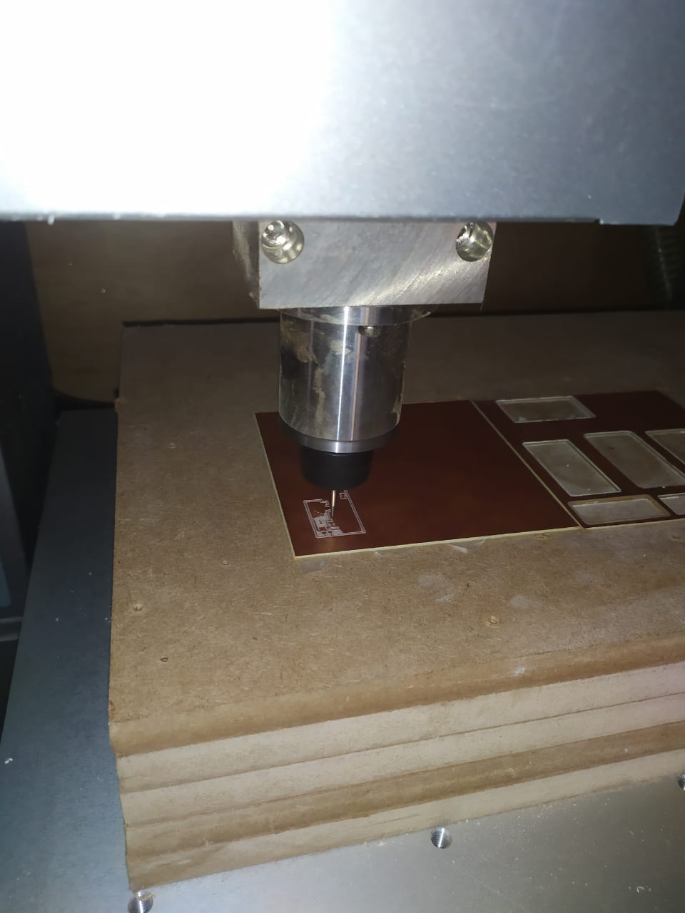
For the speeds and feeds we used 60 mm/min X and Y axis feedrates, and 120 Z axis plunge rate.
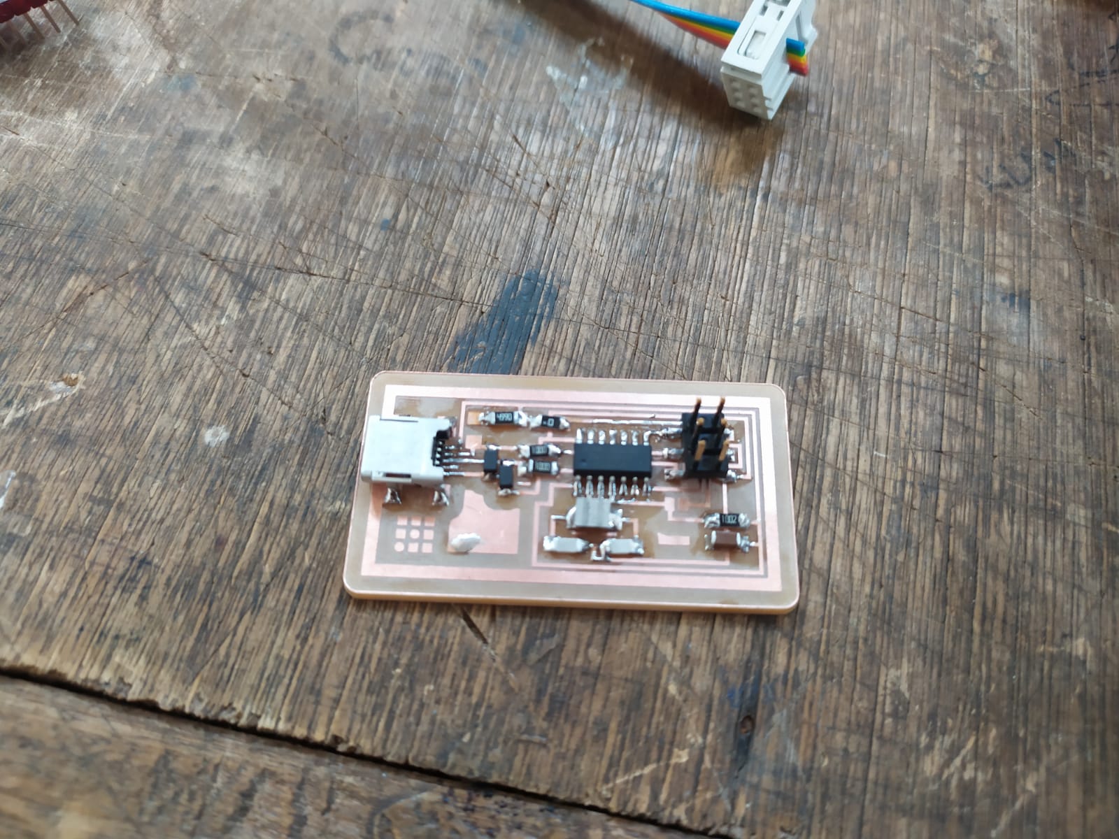
Soldering
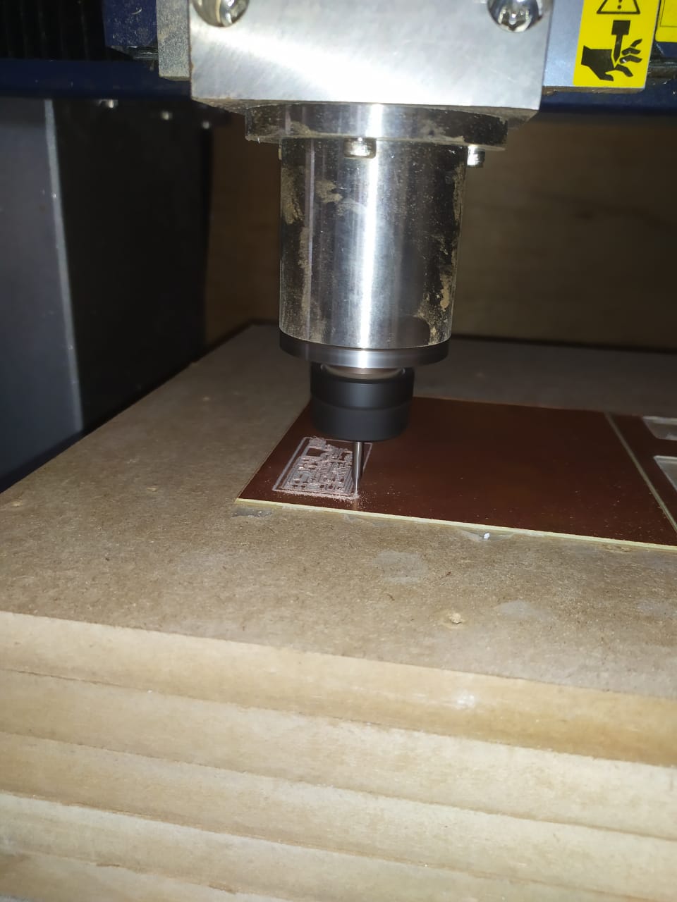
After that we cleand and soldered the components
at first I putted the wrong Resonator, wich I corrected later with the right one.
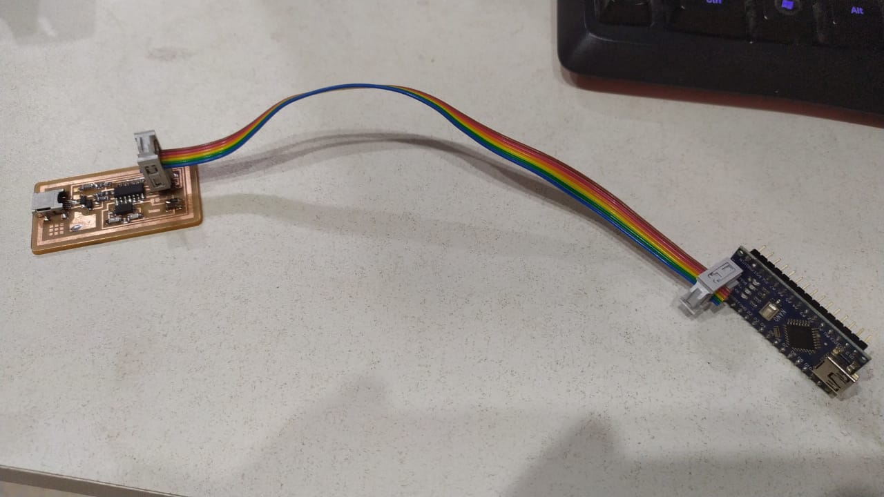
I tried to program the programmer with an arduino Nano, but I ran out of time, no luck..
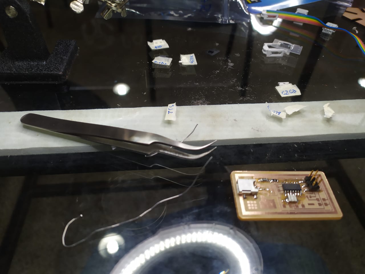
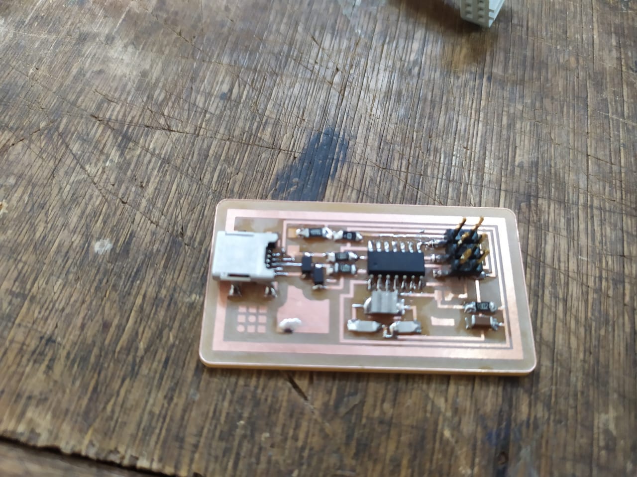
After that I putted the programmer in my backpack and it broke, So I had to start over and make a new one.
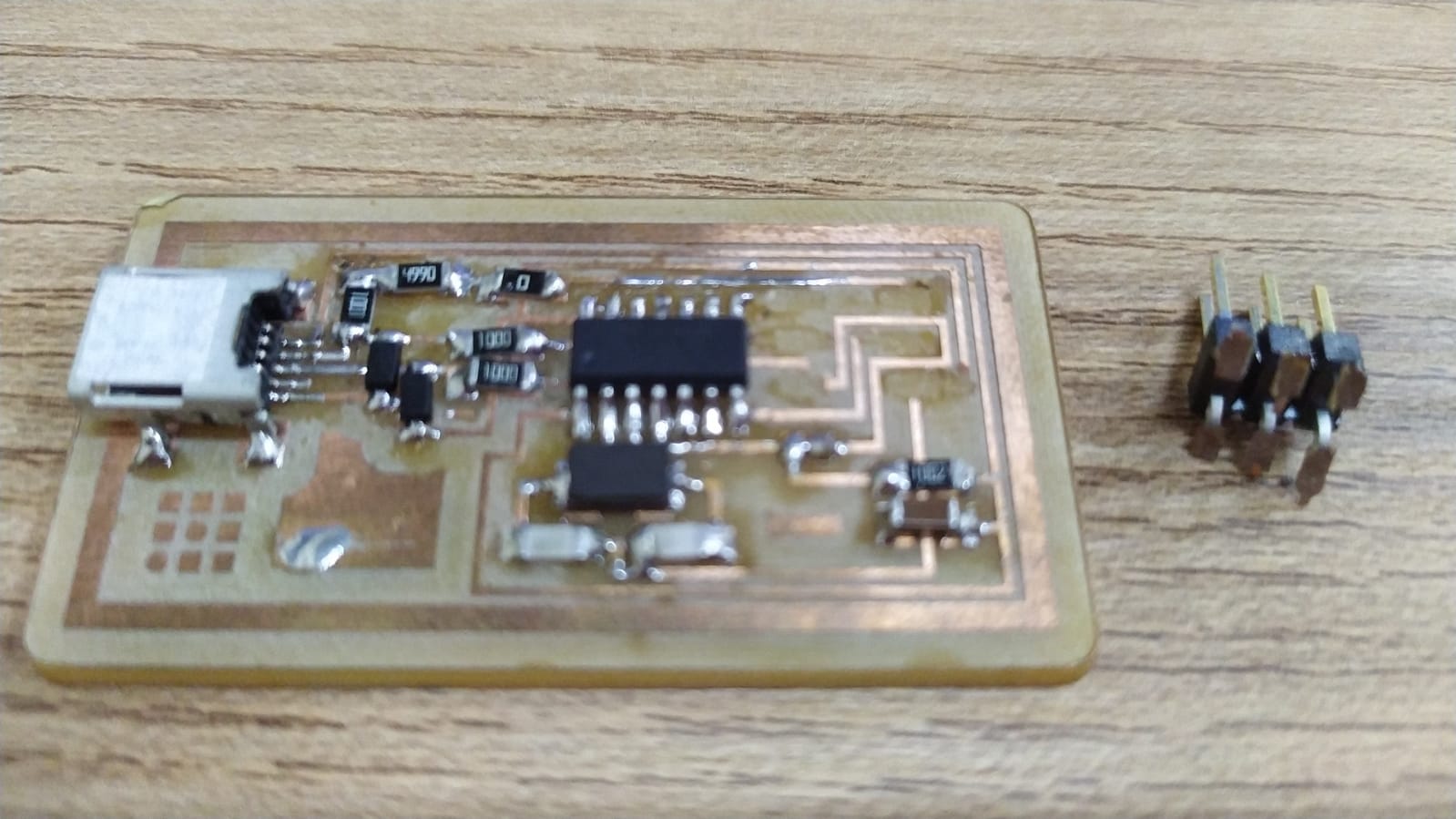
This time I made a small adjusting using a different schematics that uses the same resonator I putted incorrectly in the first place.
Programming
To “program the programmer” we used the Atmel ICe programmer from the lab.
I used linux Ubuntu to run the program in my computer.
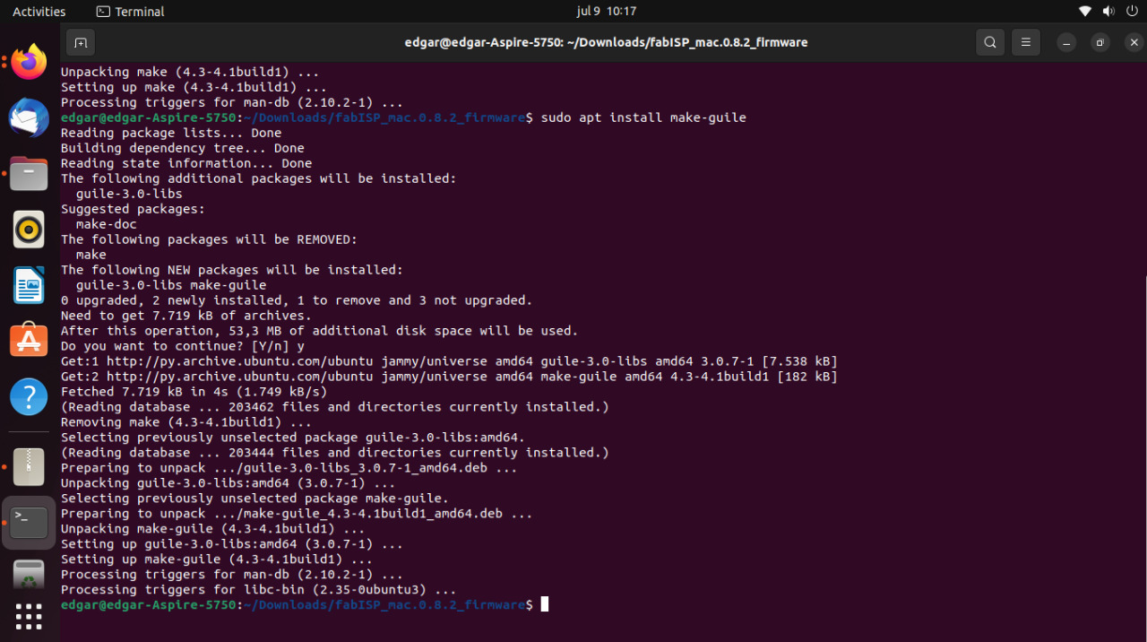
The first thing I had to do was to install AVRdude from the terminal, typing the following commands:
sudo apt-get install flex byacc bison gcc libusb-dev avrdude
sudo apt-get install gcc-avr
sudo apt-get install avr-libc
sudo apt-get install libc6-dev
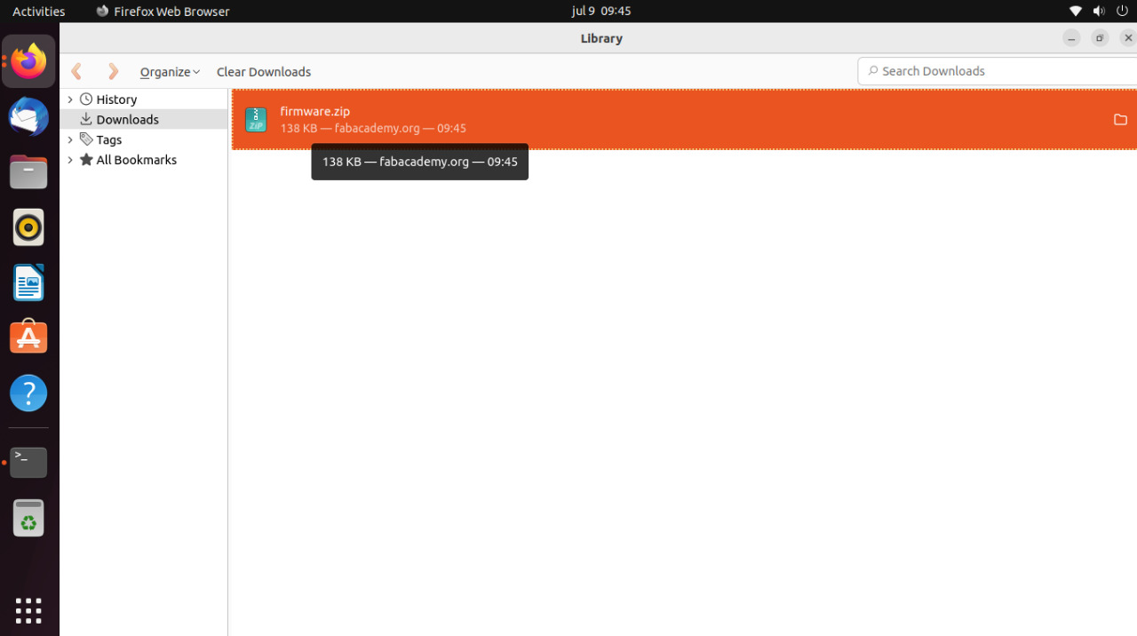
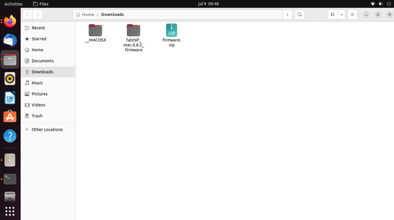
I downloaded the Fab ISP Firmware from the fab academy repository, and had to modify the makefile File changing the programmer for the atmelice ISP we have on the lab.
AVRDUDE = avrdude -c atmelice_isp -P usb -p $(DEVICE) # edit this line for your programmer
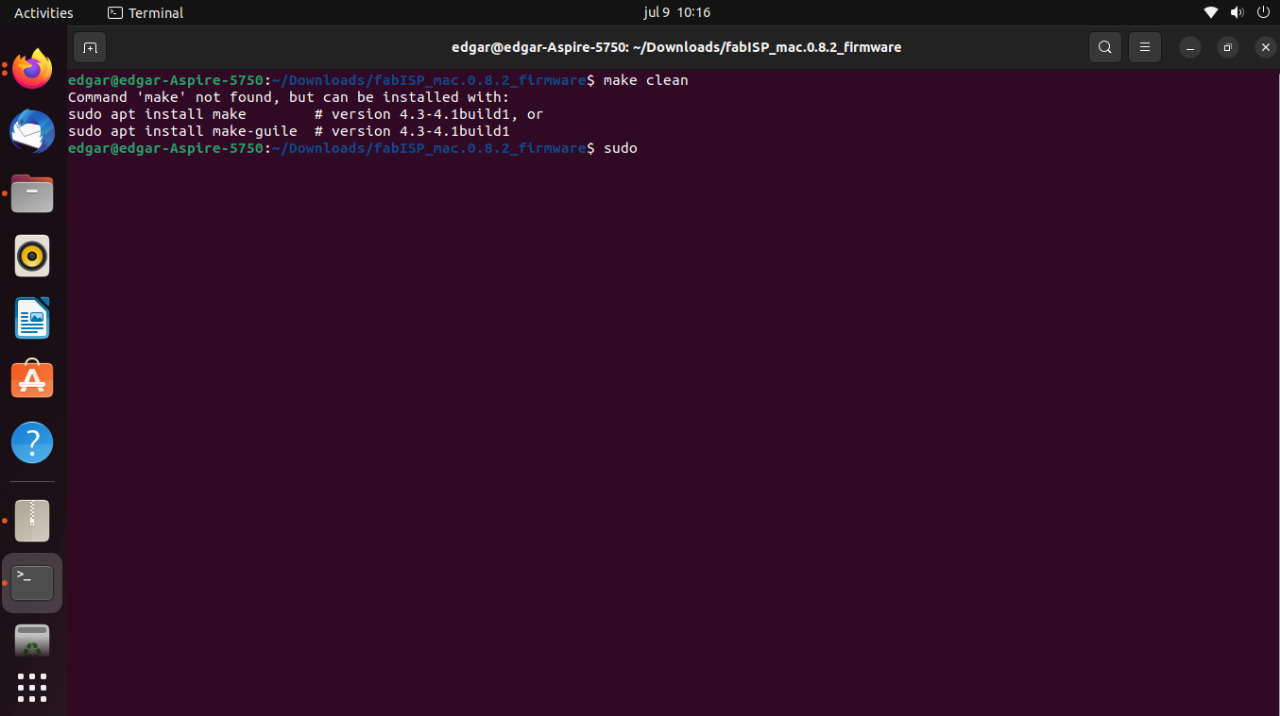
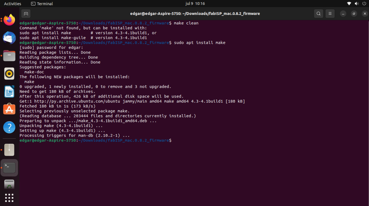
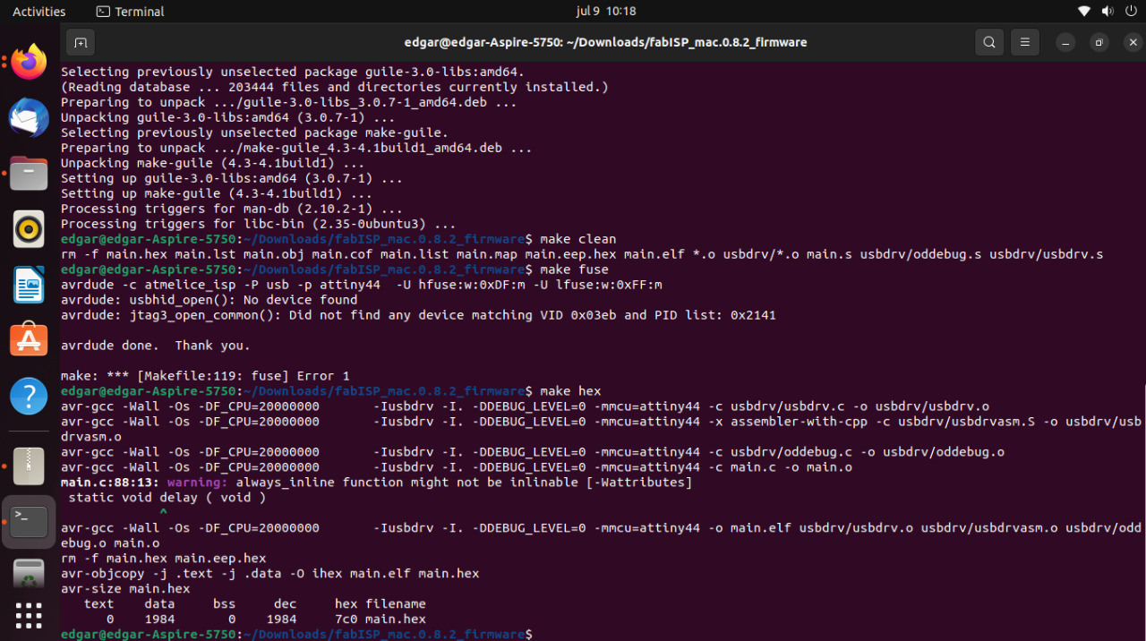
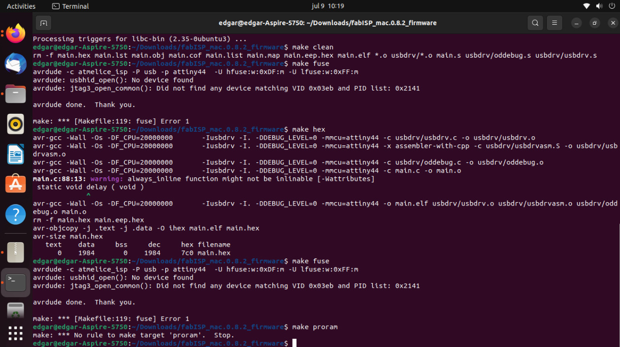
and then the only thing left to do was to compile the firmware into the board using the following commands in the linux terminal
make clean
make hex
make fuse
make program
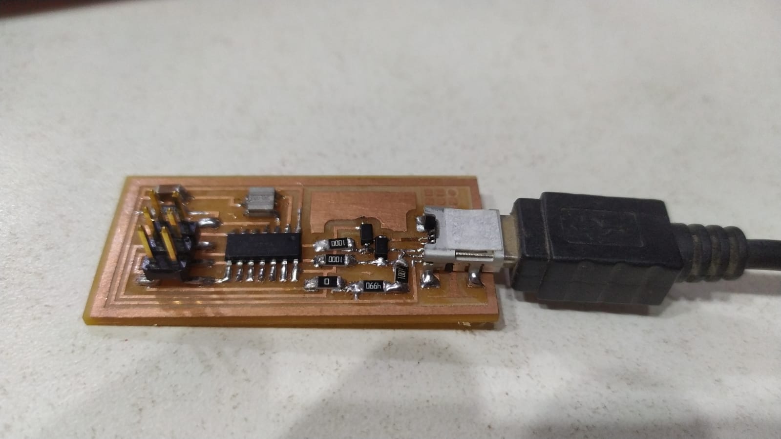
to try the programmer since I was a little late on this assignment I used the board from a posterior assignment to test if it was working properly.
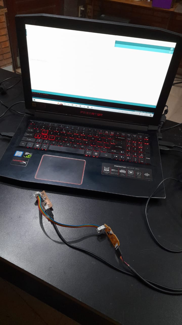
It was a Hello ftdi 45 echo code made in week 07
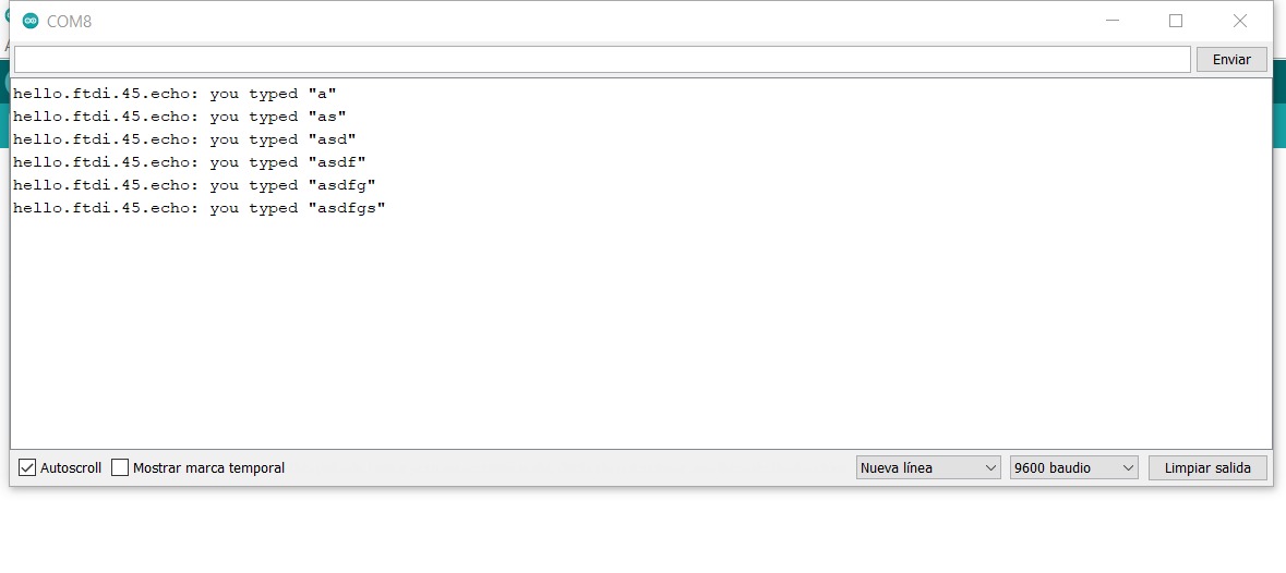
With this I can Conclude the programmer is working.