7. Electronics design
The first thing to do for this week is to quote all the things expected of me to do.
Group assignment
- Use the test equipment in your lab to observe the operation of a microcontroller circuit board (in minimum, - check operating voltage on the board with multimeter or voltmeter and use oscilloscope to check noise of operating voltage and interpret a data signal)
- Document your work (in a group or individually)
Individual assignment
- Redraw one of the echo hello-world boards or something equivalent, add (at least) a button and LED (with current-limiting resistor) or equivalent input and output, check the design rules, make it, test it.
Learning outcomes
- Select and use software for circuit board design
- Demonstrate workflows used in circuit board design
Have you?
- Linked to the group assignment page
- Documented what you have learned in electronics design
- Explained problems and how you fixed them, if you make a board and it doesn’t work; fix the board (with jumper wires etc) until it does work.
- Included original design files (Eagle, KiCad, - whatever)
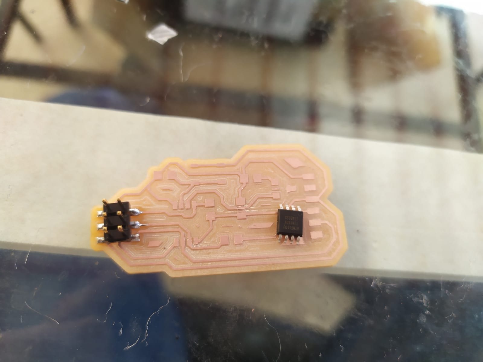
- Included a ‘hero shot’ of your board
- Loaded a program and tested if your board works
LED Calculation
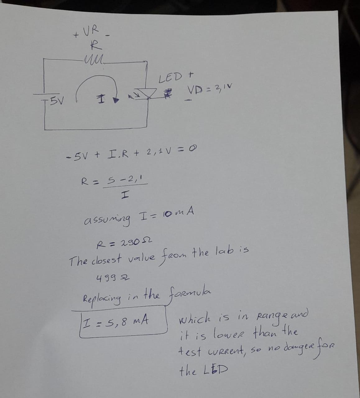
First thing is to check out the product´s page to now the LED´s working voltage, wich according to this page is 2.1V. and the test current is 10mA.
To calculate the LED resistor I watched the video from Ben Finio´s Channel and made the following schematic since our circuit works with 5V logic, also I choose the value closer to the resistor We had on the lab.
Eagle
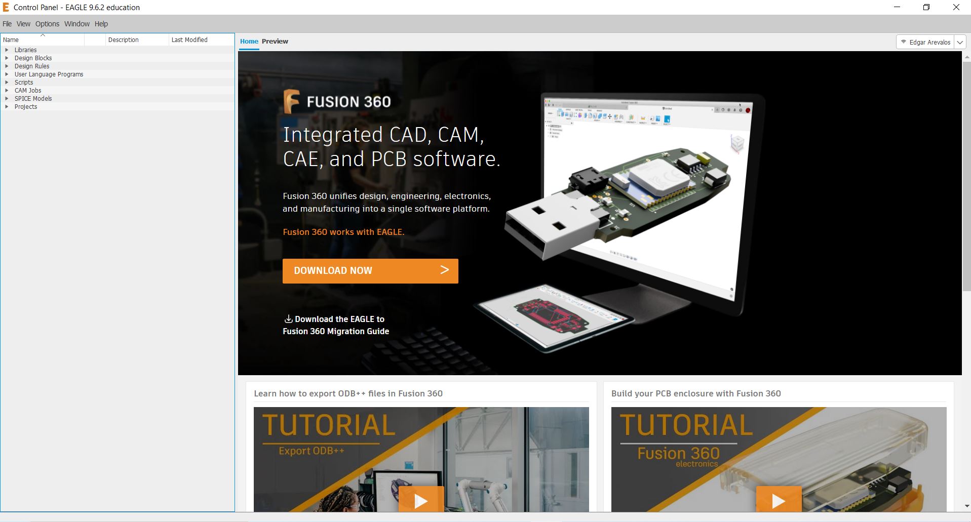
I installed Eagle from the official webpage, using my existing autodesk account I logged in, after that I followed my instructor tutorial on youtube (it is in spanish).
I used André Pulcino´s library for eagle to find all the components I needed that were missing from the eagle and sparkfun libraries, installed both and managed to make the schematic.
André Pulcino week 7 fab academy
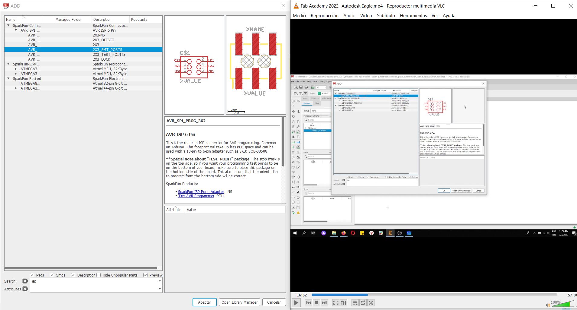
For the IC we choose the Attiny45 and used this board as an example
we added the parts in eagle using sparkfun library and Fab.lib downloaded from André Pulcino´s Fab academy page, the hardest part was to get familiar with the eagle´s search engine, because you have to put almost the specific word to find each component.
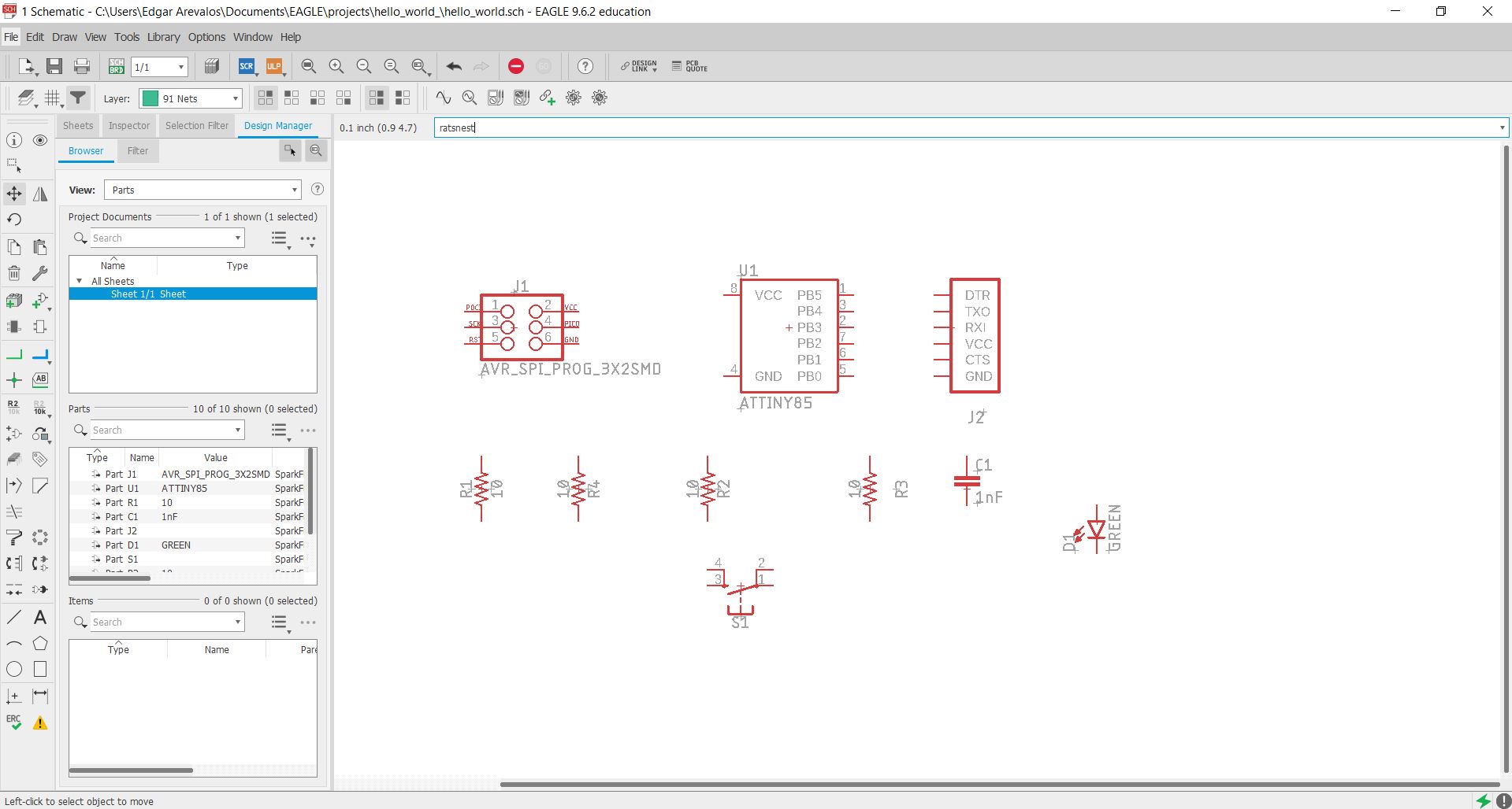
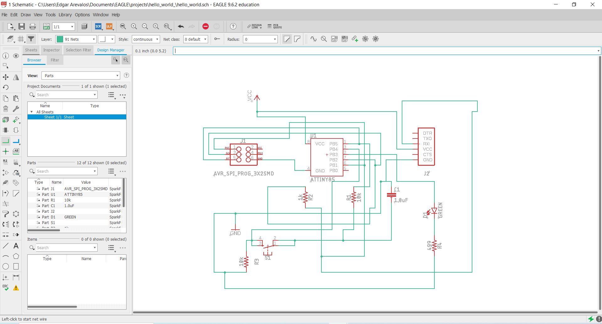
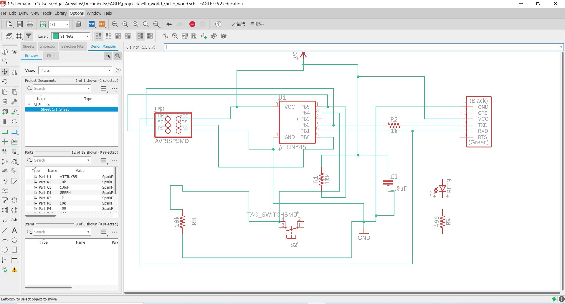
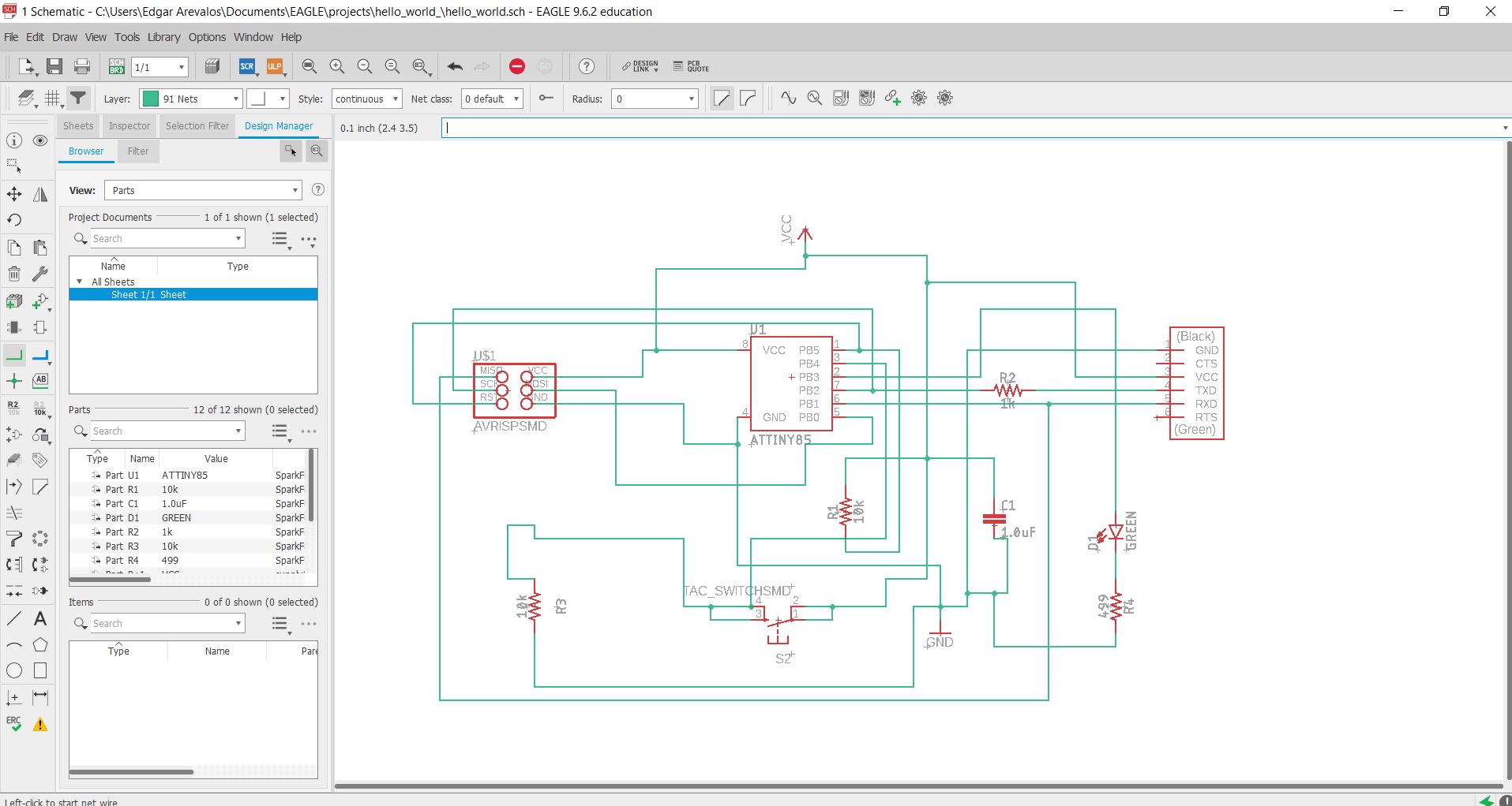
After joining the wires in the schematics, I selected create board from schematics in the upper left corner of the screen.

I have ordered all the components and then realized some of the components I choose were not going to work.
So I found a replacement of those components with the help of my classmates, and had to do all the wiring again, soon after that I realized that I could just have used the replace function instead of deleting the components and rewiring. Anyways after having the right schematics.
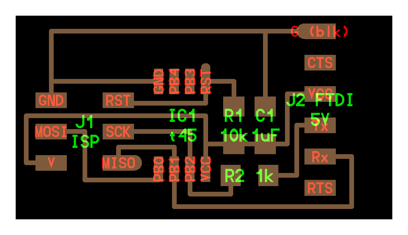
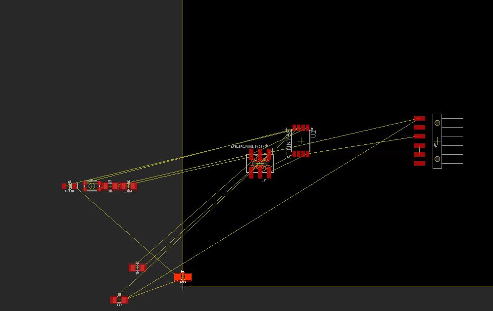
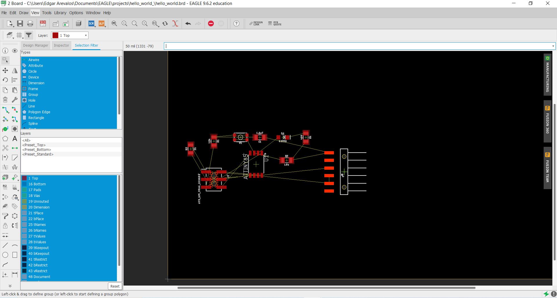
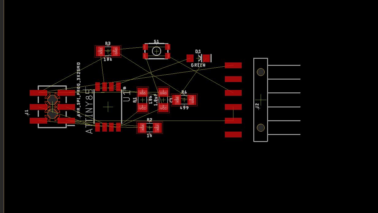
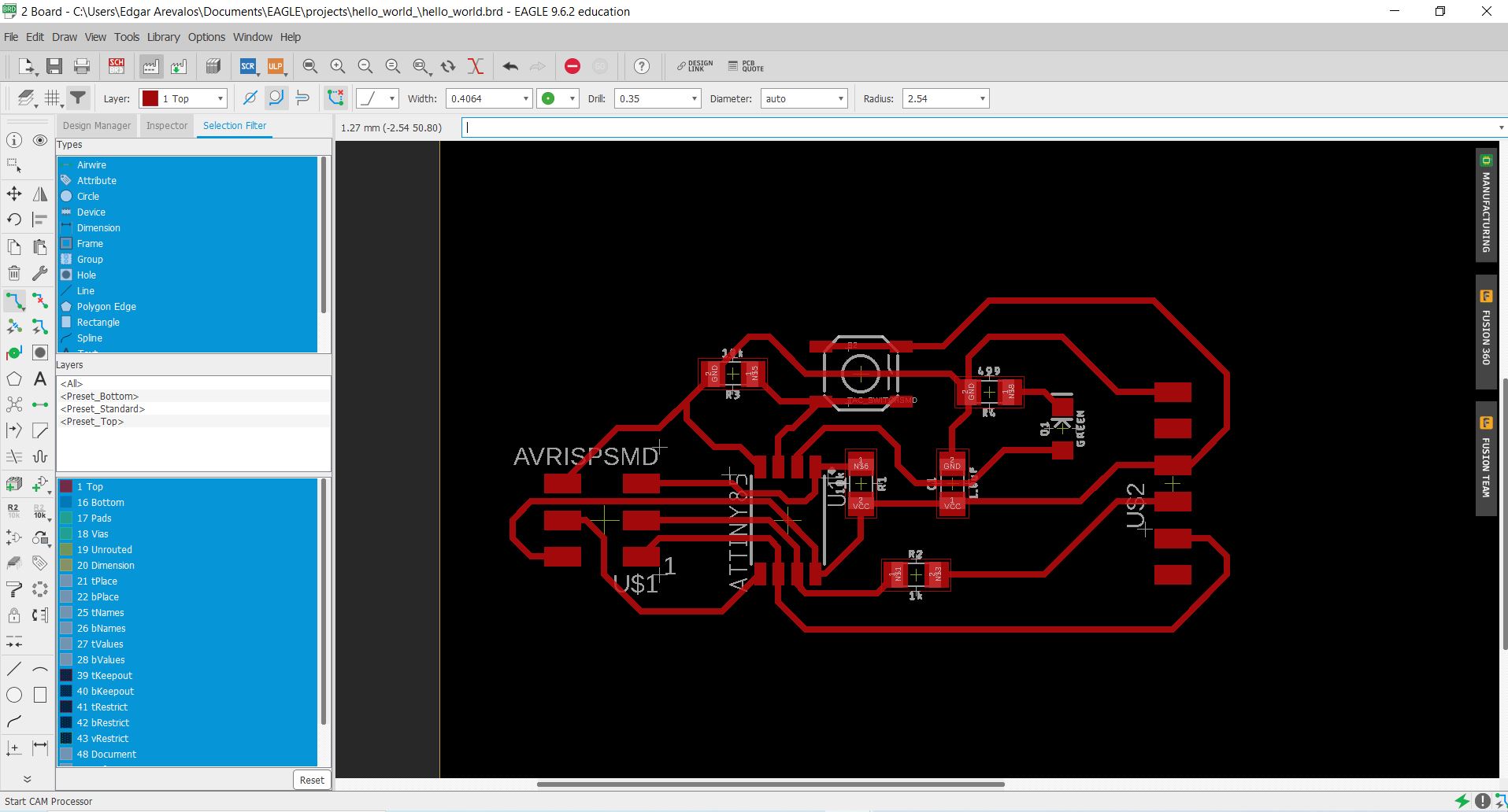
I started routing the circuit by hand trying to do as much alike as the original one. I used a 0.4mm width for the routes, and then saved the gerber file in the upper left corner of Eagle.
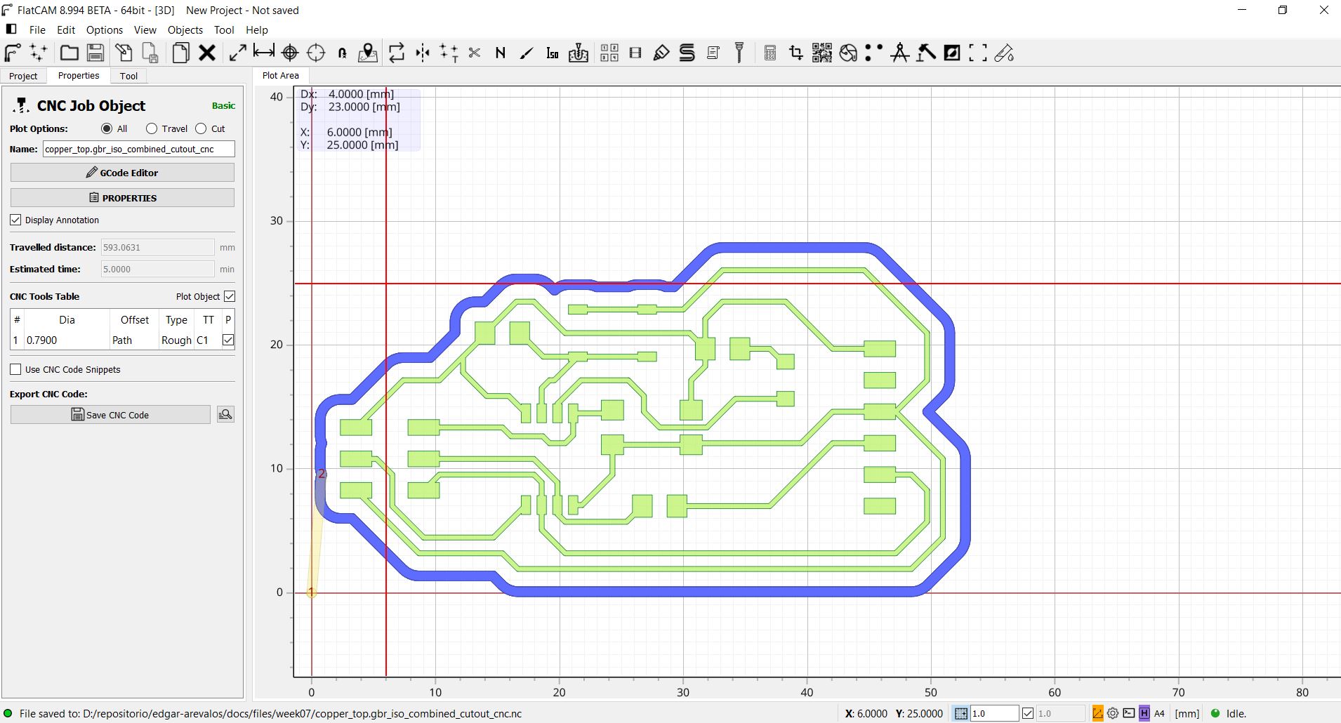
Flatcam
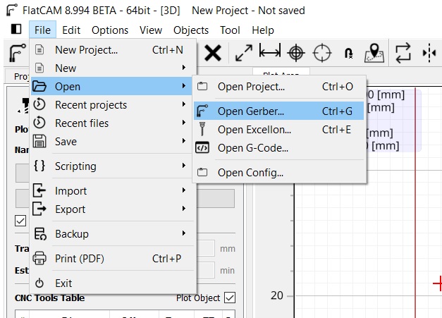
In flatcam I imported the gerber file, in this case I used the top layer at eagle, so that was the only file I had to import in flatcam.
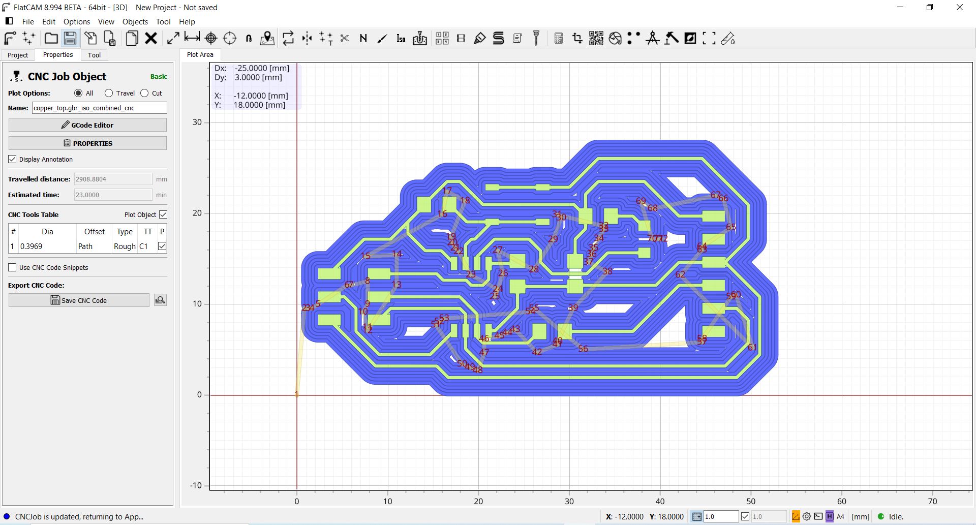
I used a 1/64 inch routing bit in the isolation routing menu and the result was the following.
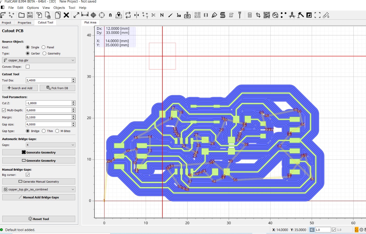
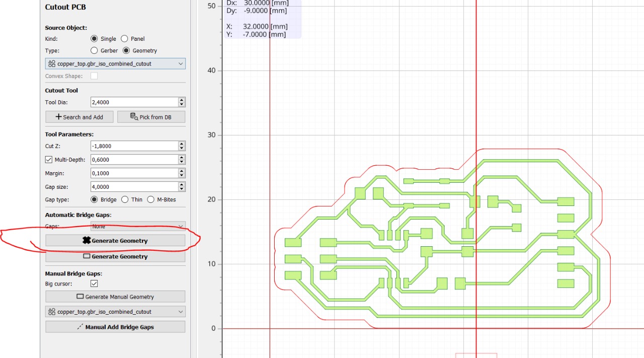
After that I selected the geometry and selected the cutout tool using the same geometry as my isolation routing.
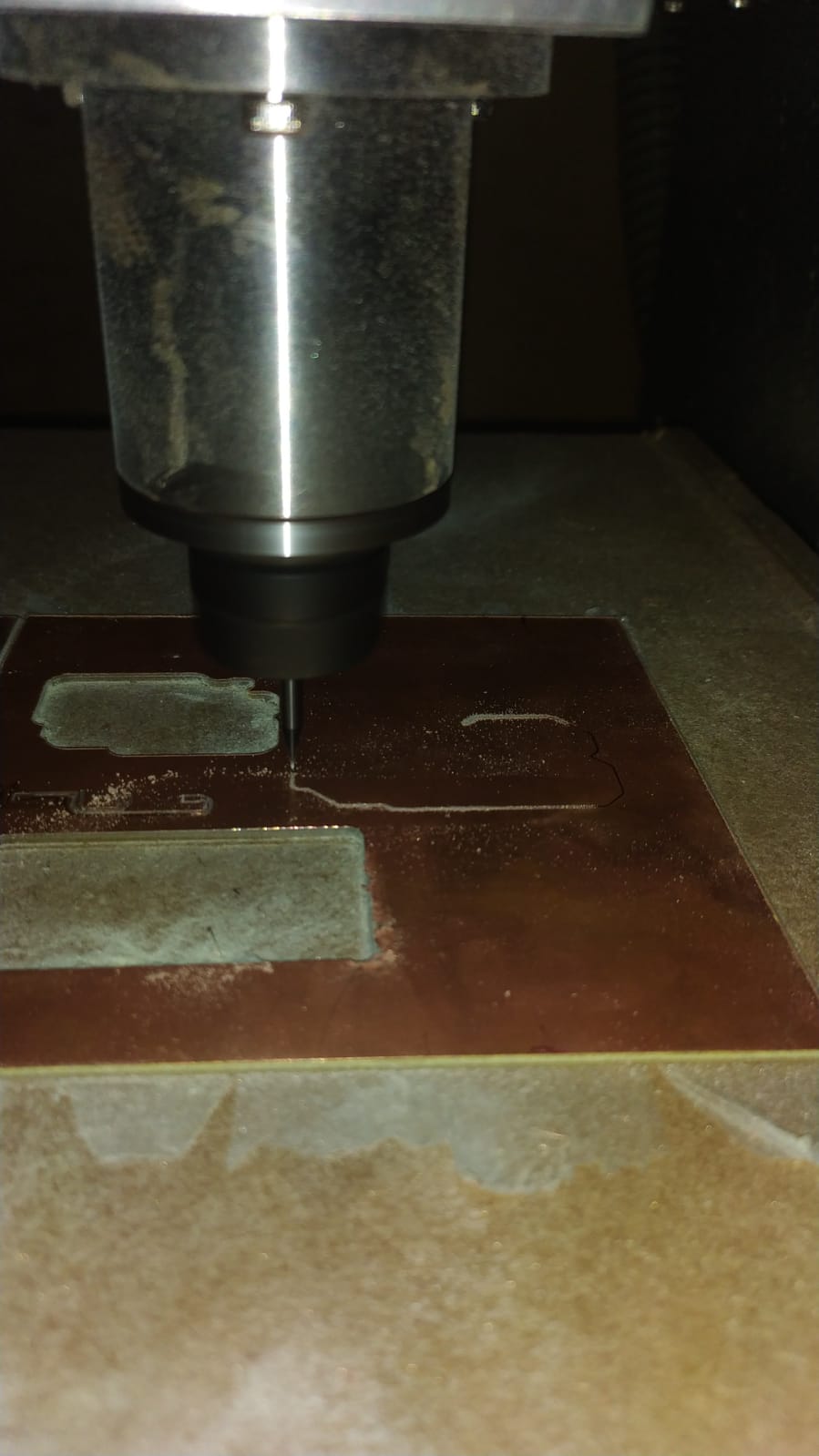
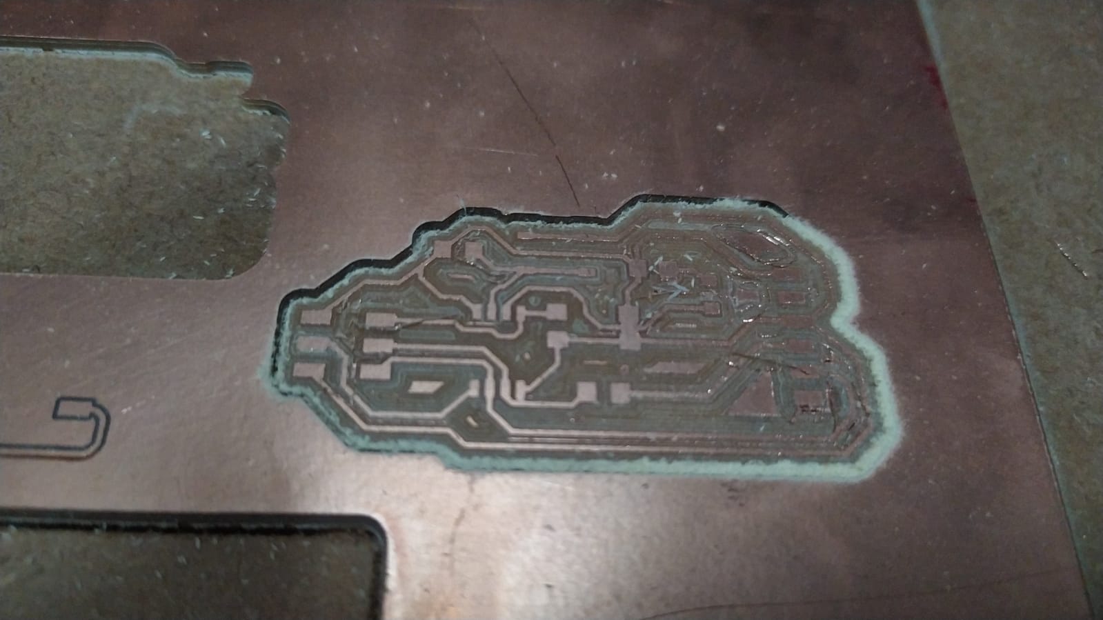
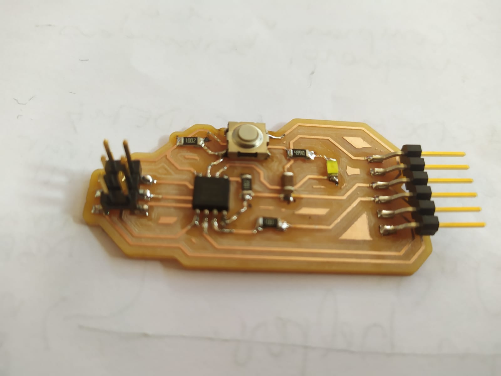
Milling
I used 120mm/min in the roland mx540, and the result was quite good in exception of two small routes that intersected. I used a cutting knife to separate them and the board was ok after that.
I soldered all the components and then the board was ready for programming.
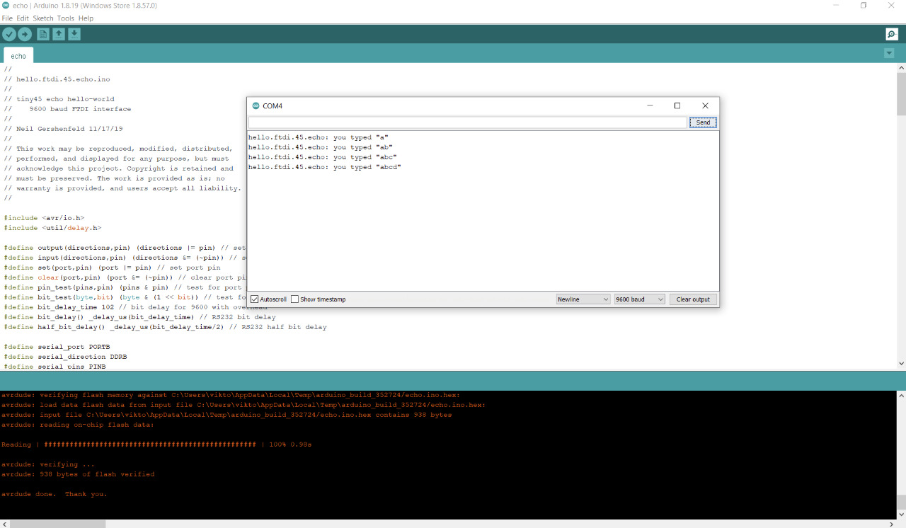
Programming
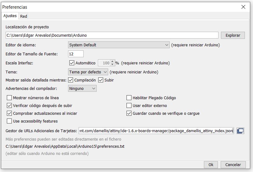
for the microcontrollers library for arduino I used https://raw.githubusercontent.com/damellis/attiny/ide-1.6.x-boards-manager/package_damellis_attiny_index.json this link.
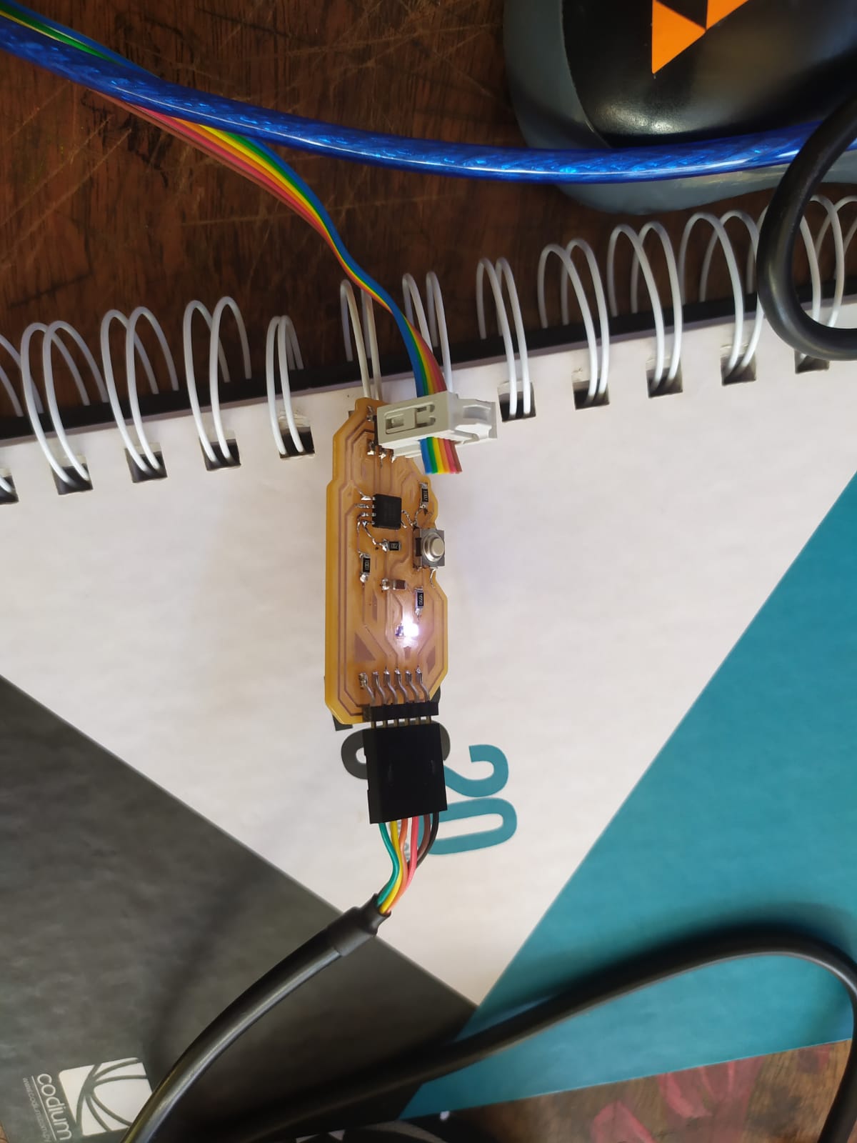
For the first program I used the following code to make my led blink
Files
The Files made for this project are down in the links below.