Final Project
Assessment
Document a final project masterpiece that integrates the range of units covered, answering:
- What does it do?
- Who’s done what beforehand?
- What did you design?
- What materials and components were used?
- Where did they come from? How much did they cost?
- What parts and systems were made?
- What processes were used?
- What questions were answered?
- What worked? What didn’t?
- How was it evaluated?
- What are the implications?
Prepare a summary slide and a one minute video showing:
- Its conception, construction, and operation.
Your project should incorporate:
- 2D and 3D design
- additive and subtractive fabrication processes
- electronics design and production
- embedded microcontroller interfacing and programming
- system integration and packaging.
Learning Outcomes
- Create your own integrated design
- Demonstrate 2D & 3D modelling capabilities applied to your own designs
- Select and apply appropriate additive and subtractive techniques
- Demonstrate competence in design, fabrication and programming of your own fabbed microcontroller PCB, including an input & output device
Have you?
- Made your slide: 1920 x 1080 pixels with your name, project name, Fab Lab name, a photo/render/sketch of your project, a brief description of what your project is/does
- Made a ~1 minute (10MB/1080p) video of you explaining your project
- Made a separate Final Project page that briefly summarises your project
- Included the BOM (Bill of Materials) for your project
- Linked from this page to any weeks that you worked on your final project
- Linked to your presentation.png and presentation.mp4
- Included all of your original design files in the archive (2D & 3D, board files & code). No external hosting of final project files - discuss file sizes with your instructor
- Included the license you chose
- Acknowledged work done by others
Introduction (What does it do?)
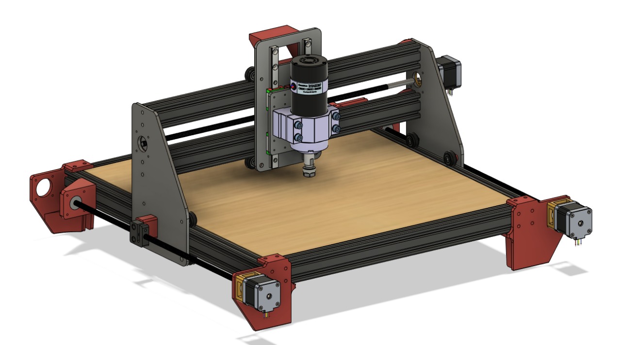
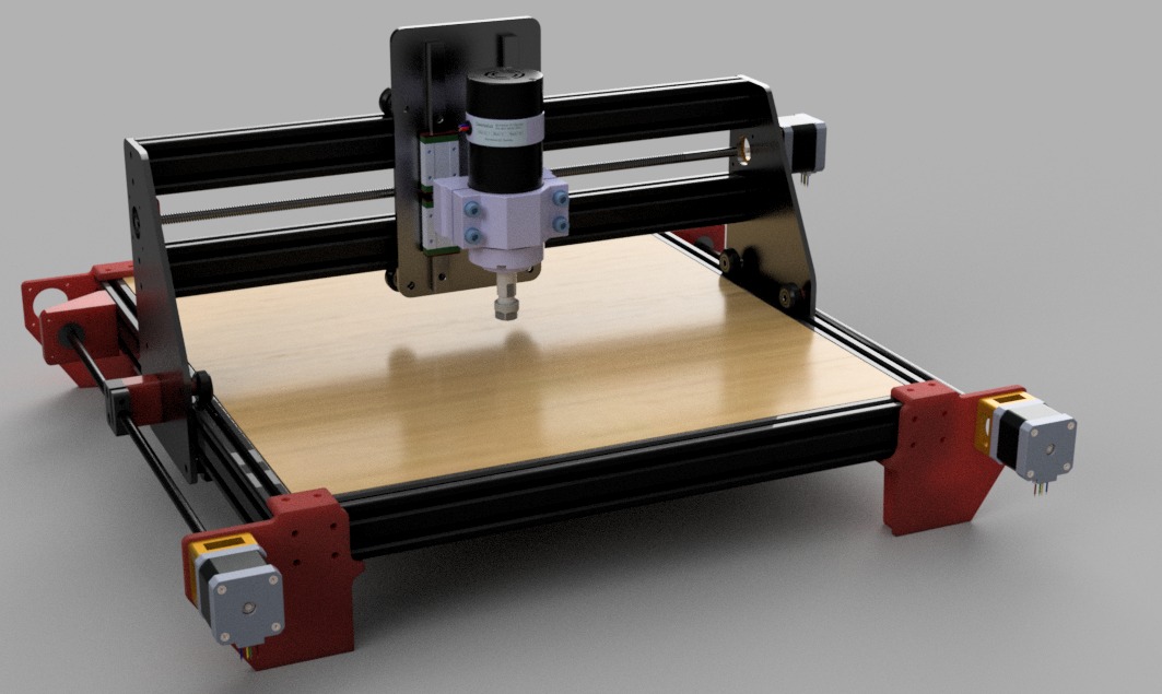
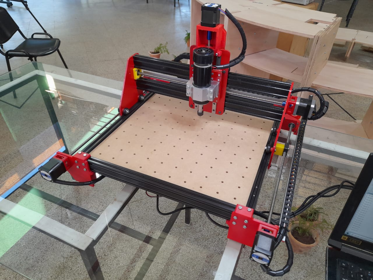
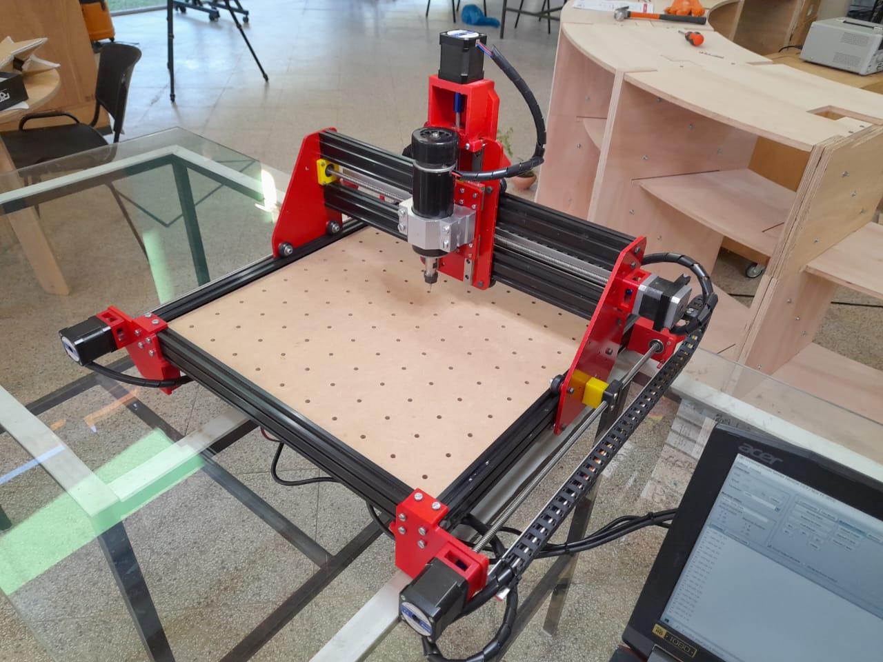
For my final project, I want to build a Low Cost, rigid and robust CNC mill, capable of machining, wood, acrilic, PCBs, and maybe aluminium (slowly), with great precision. The main function I want this machine to have is the hability to produce parts for other machines very reliably. That`s the main reason I want to use leadscrews with anti backlash nuts.
Who´s done it beforehand?
In this section I collected the most information about fab academy collaborators I could find in 3 hours of my time wich worked on cnc machining. Their work will help me save some time in developing my final project, and I hope my work will help future students as well.
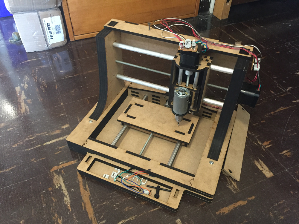
He built a Low-cost CNC mill from scratch (under 100$), specifically for milling PCBs.
The materials he used were: - a laser cutted MDF frame with metal rods as linear guides. - a 12v DC motor with a drill chuck as an spindle.
-
he designed his own motor drivers on output week design.
-
he created a network to connect to each stepper driver sepparately.
It seems that he never finished his machine because there is no documentation of the machine working. Even though it really helps to see other people paths to learn from their expieriences.
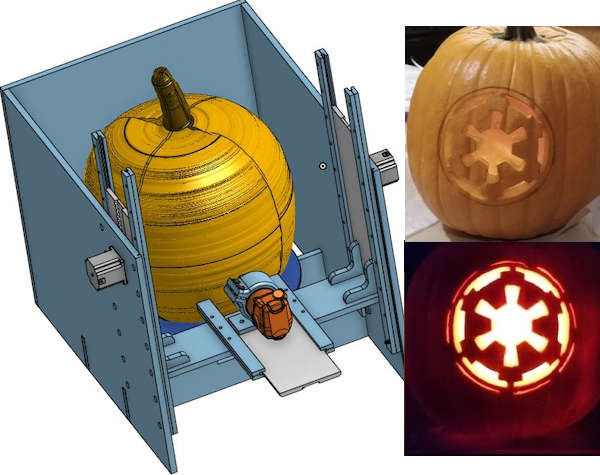
He built a CNC lathe that can machine a 2D drawing mapped onto an 3D irregular sphere.
What did he do?:
-
Plywood frame with rails fabricated HDPE linear rails and DIY “rack and pinion systems”
-
For electronics he used Satchakit GRBL board
-
This project is highly dependent on previous work on generation of tool paths in G-Code and execution of the G-Code using GRBL and CNC control using Universal G Code Sender (UGS).
This documentation helped me find Jens Dyvik´s work wich is very interesting for my line of work.
Jens has very impressive work wich I intend to continue following after finishing the fab academy, but I believe it is more advanced stuff to talk about more in this page. Even though you can check this 2 impressive machines he made.
These are machine design elements that are used at the CBA when trying new custom machines: they’re parametric, aim to be reconfigurable, and can be made in the lab with a minimum set of stock hardware.
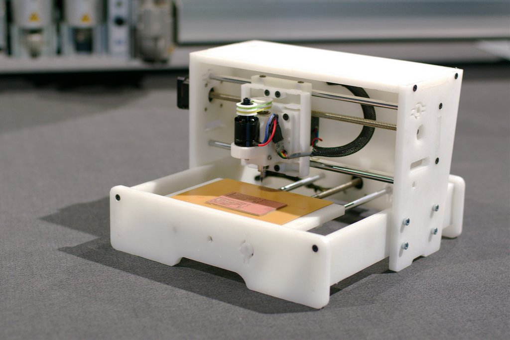
Fab Neo is a compact milling machine designed for milling circuits boards.
The Z axis features a simple flexure based motion system driven by a CAM. The X,Y stages all run on Delrin plain bearings which are easily machined, and driven by Lead screw stepper motors. The spindle is a BLDC motor attached to a bearing block (Modella).
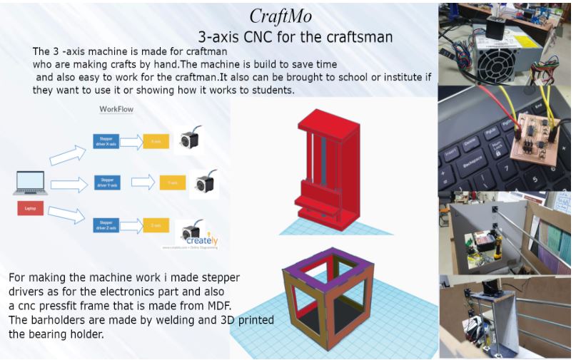
This is a CNC machine made of a wood frame and steel rod linear guides, specially designed for craftmans.
He used his own drivers and his own application for controlling the software of the machine.
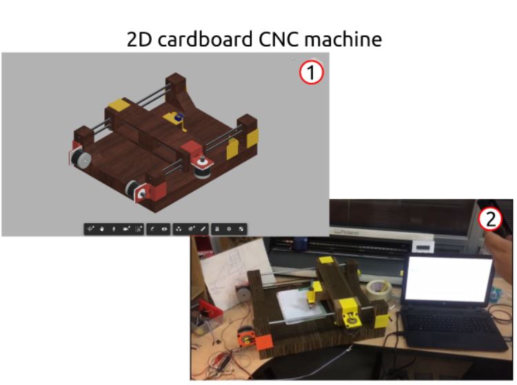
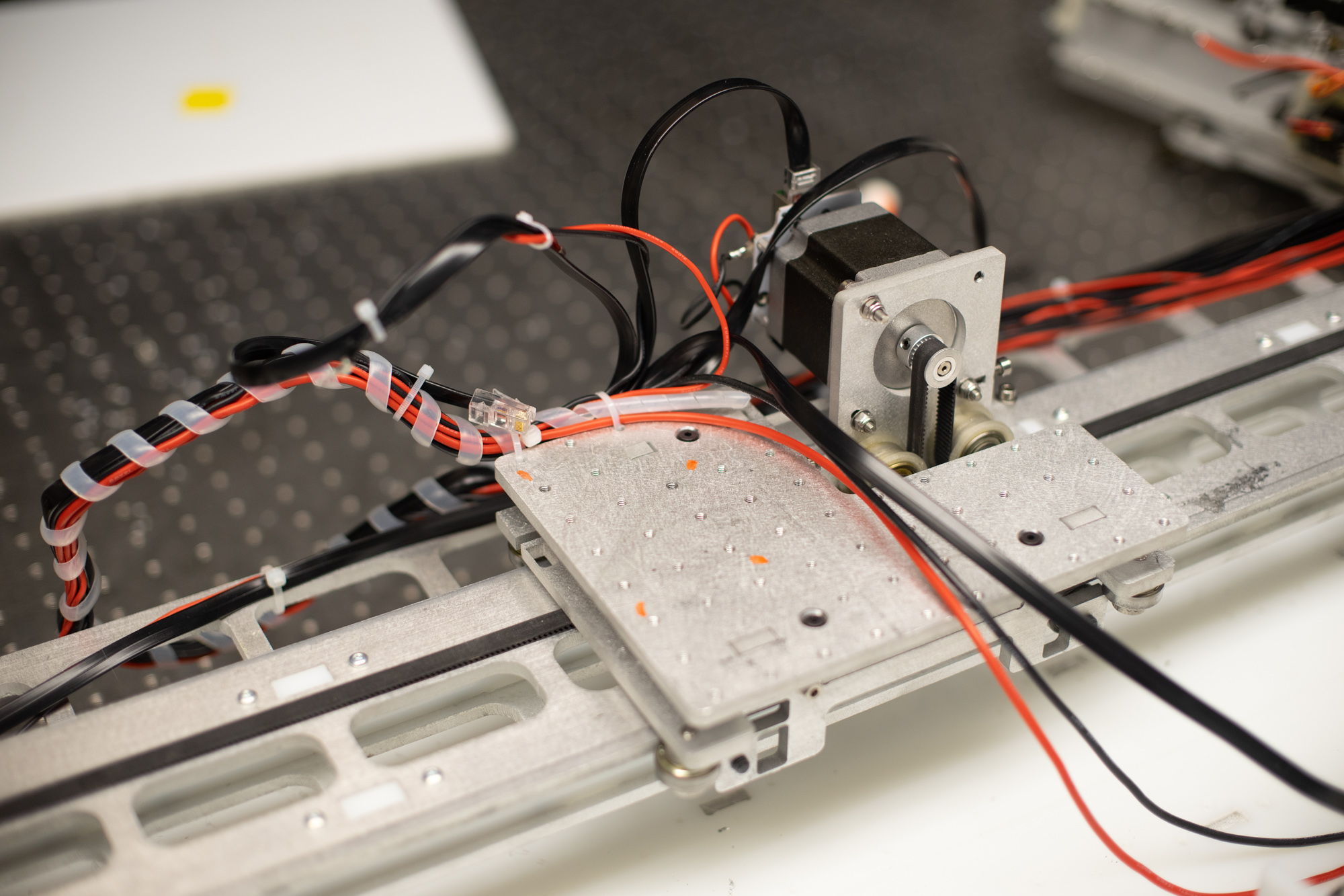
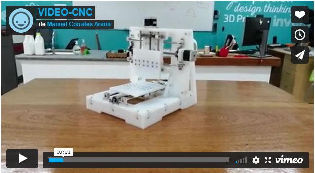
They made a cardboard drawing CNC machine, using a fabduino board fabricated in the lab, with a connection module for the drivers (DRV8825). and used Universal Gcode Sender to communicate with the board. The main structure is cardboard, and the linear rails are steel rods.
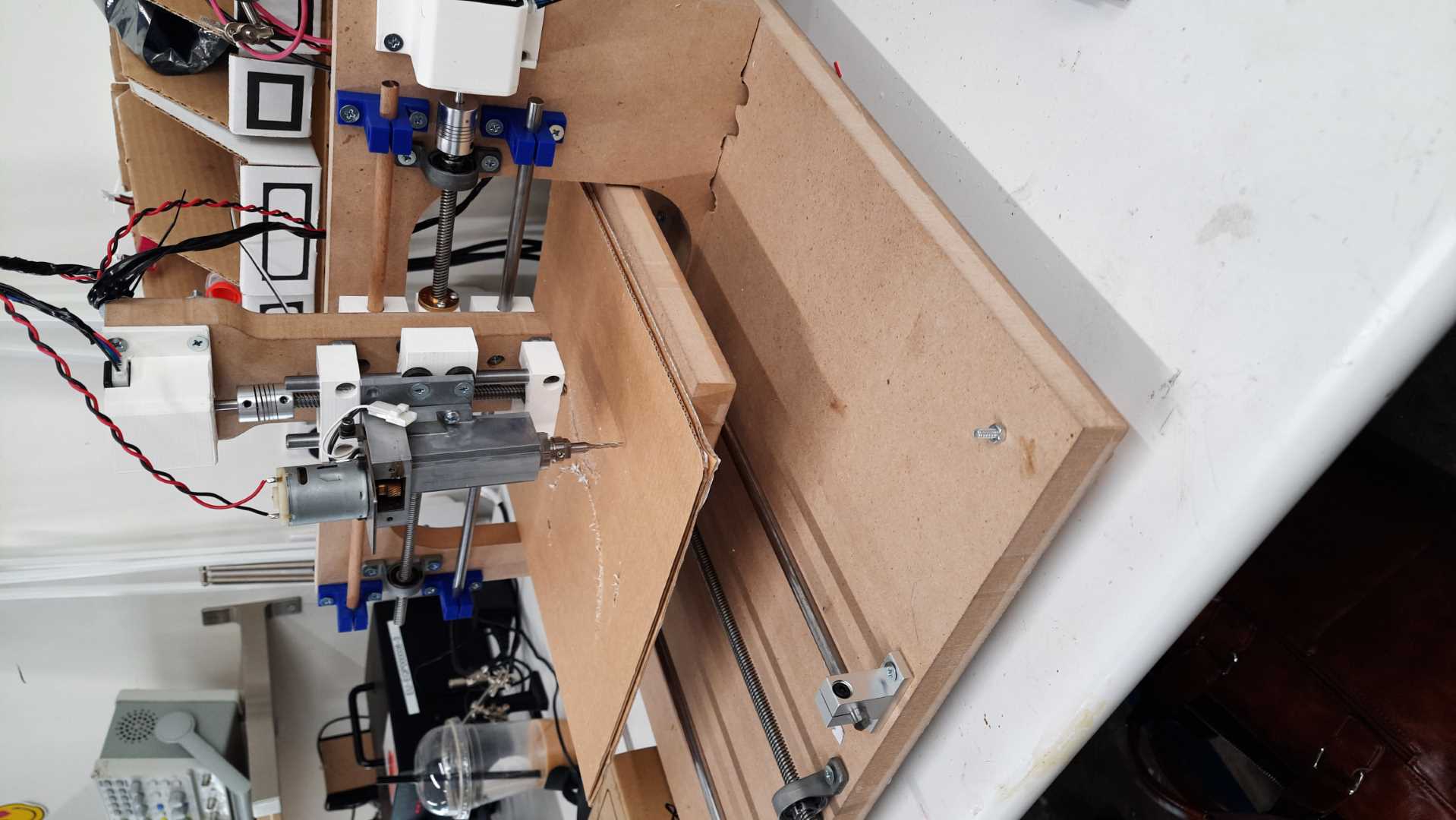
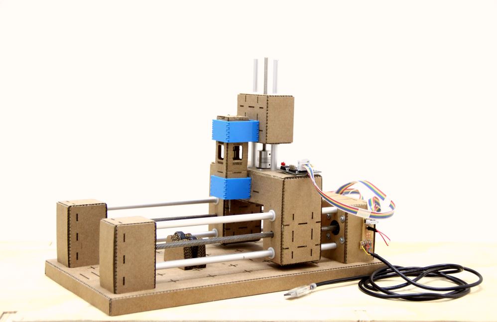
He made the main structure out of MDF and 3D printed parts, it is a moving bed cnc machine with a DC motor and coupler as a spindle with a drill chuck.
For electronics he used arduino UNO with a CNC shield.
They built a CNC machine to draw letters and geometric figures.
- The main structure is made of HDPE
- The rails are 8mm rods
- the pencil holder is 3D printed
- Arduino UNO is the main board with universal gcode sender.
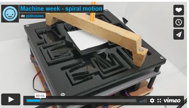
They did a flexure movement CNC, to control the motors they use 3 nodes, 2 stepper motor nodes and 1 usb node to communicate with the stepper nodes.
They made a CNC tube cutter with cardboard, based on the modular cardboard machine of Nadya Peek. They made their own array of boards called Fab_Net.
What did you design?
For this project I designed the Gantry panels, the base of the machine, The motor mounts, the nuts supports, the pieces to hold the spindle mount, the electronics(modified version of previous works), the casing, and the clamping system for the CNC machine. My design constraints were made with the materials I had, So I divided my work in 8 Stages.
8 Stages of the design, building and testing process.
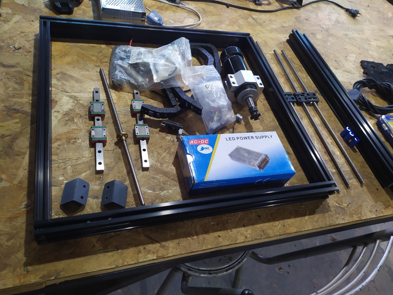
1- Materials to be used.
- 4020 aluminium profiles for main Structure.
- 500W spindle (DC motor with speed control).
- T8 leadscrew with POM anti-backlash nuts, 8mm pitch.
- Nema 17 stepper motors.
- 5mm aluminium panels for the X and Y axis.
- V-slot nylon wheels with 625 bearing.
- 12mm linear Rails for the Z axis
- 3D printed and laser cutted clamping system.
2- Mechanical design
First sketch
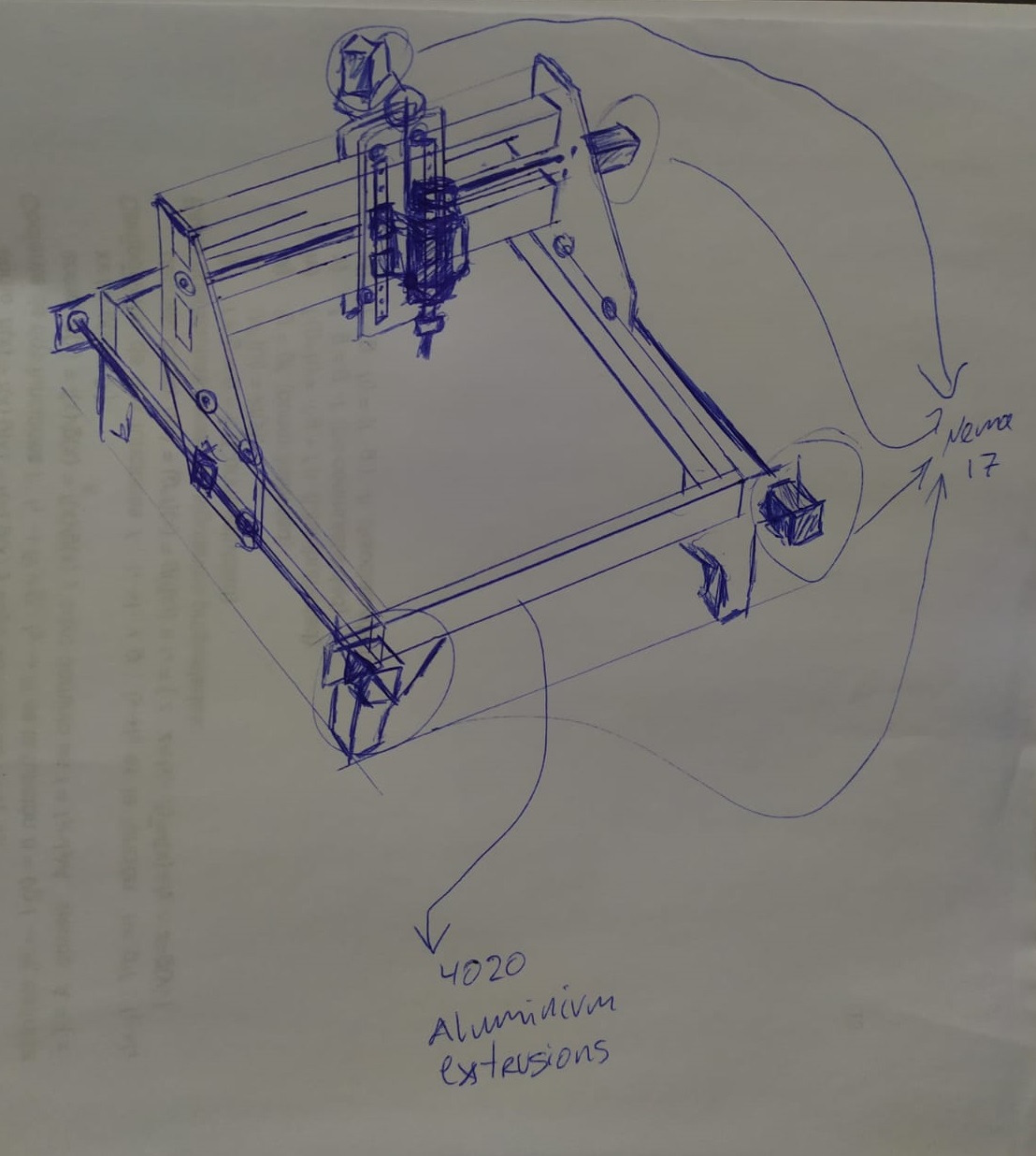
I made the design to be able to use parts I already had, laying around my shop. So, that was the first design restriction.
2D modeling
In this case the 2D modeling is a projection of the 3D modeling to be able to mill the pieces on the CNC.
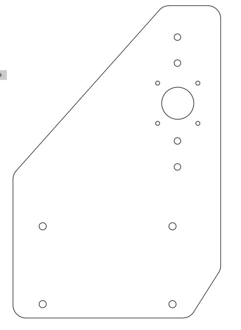
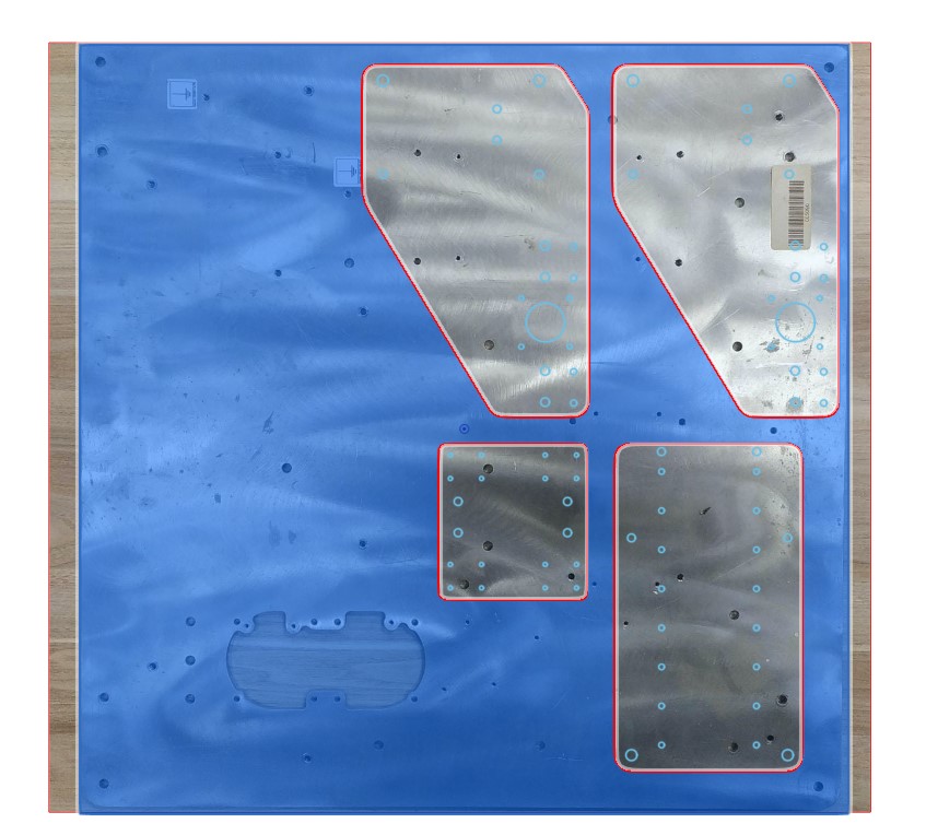
I used the Canvas tool to locate the pieces in the aluminium in order to check that the new holes don´t match-up with the old holes.
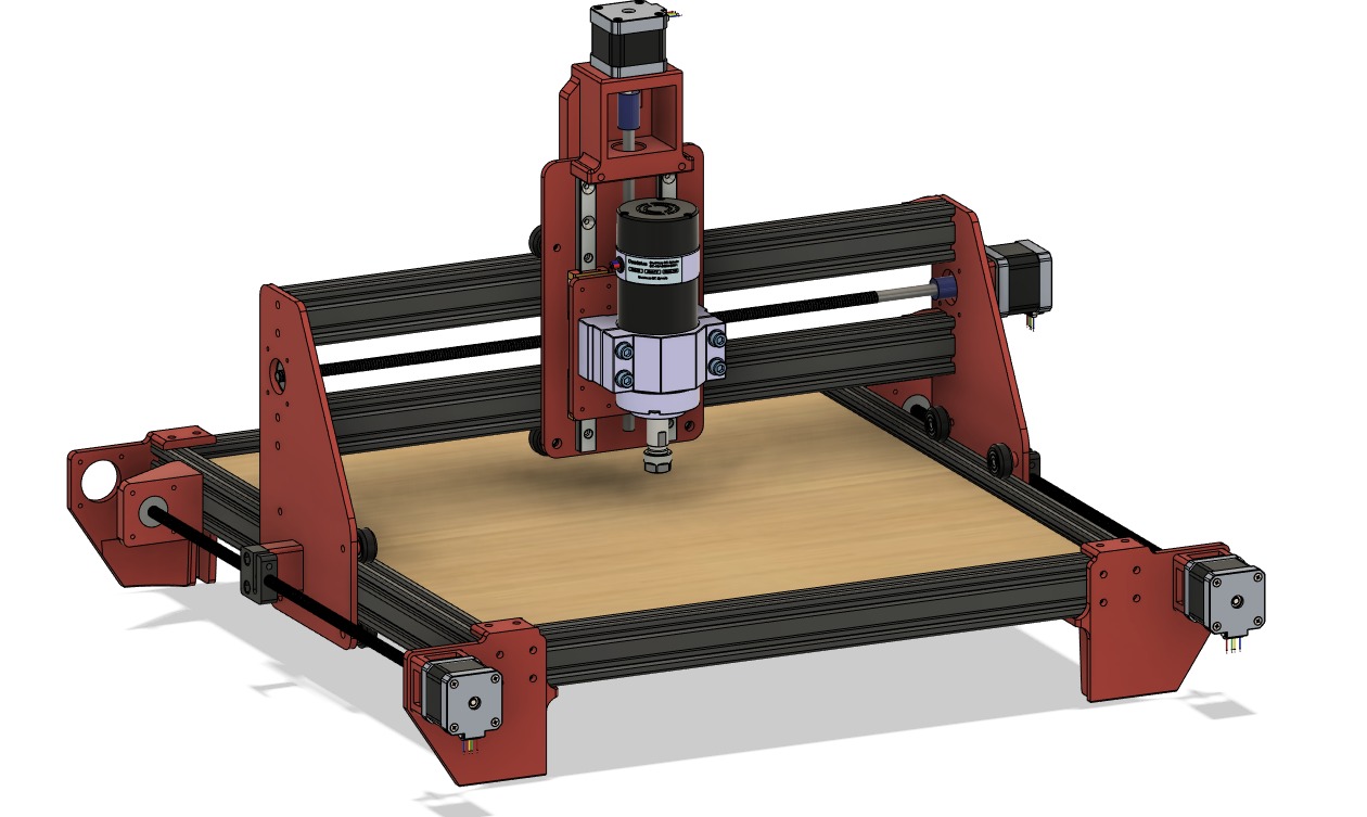
3D Modeling
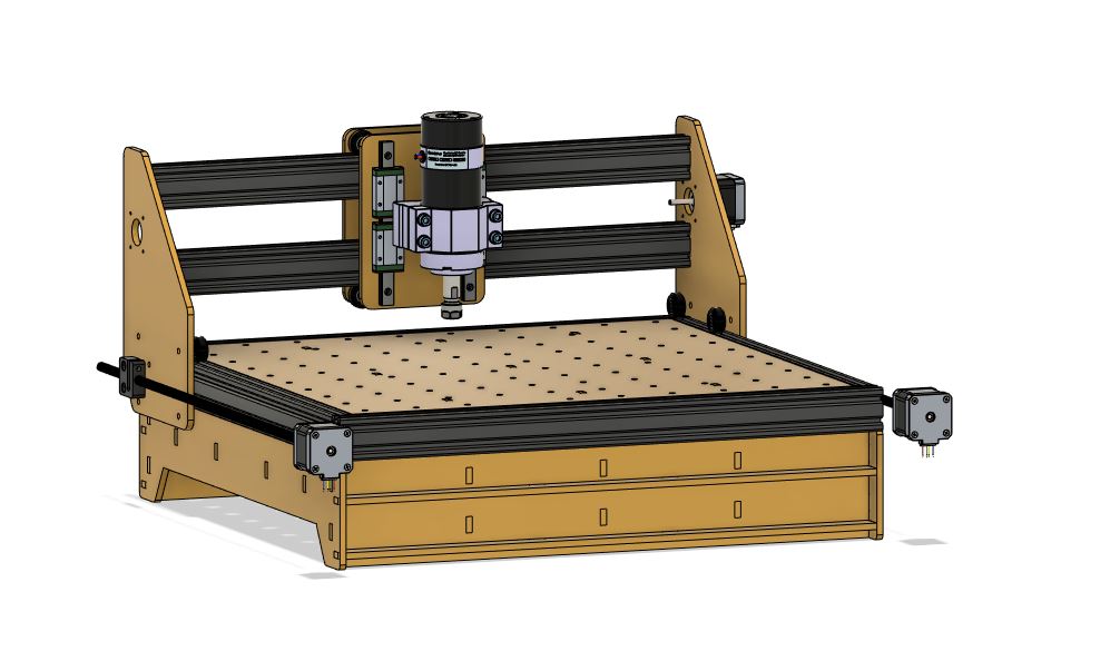
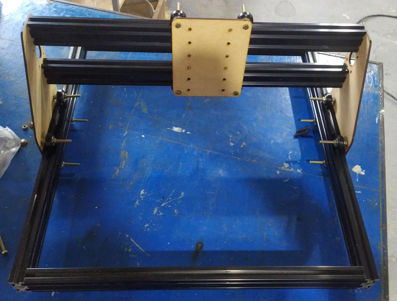
This is the main first Idea I started working with after the sketch, I tried designing a lasercut base but later I changed my mind.
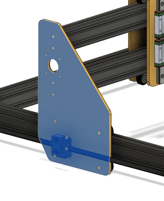
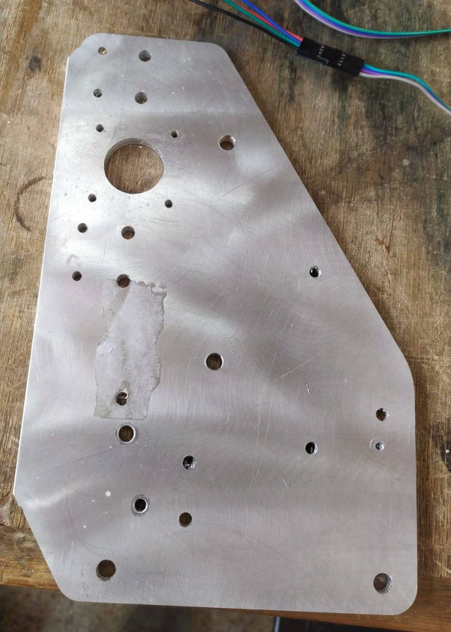
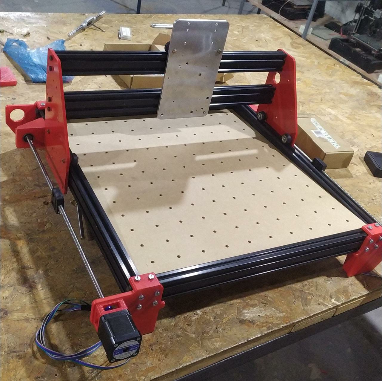
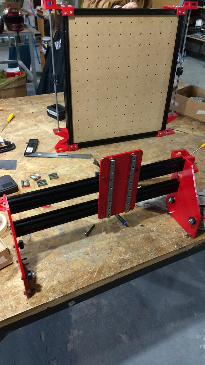
This is the first design of the side panels, the X motor is in the middle of the 2 aluminium profiles and the wheels are 10 cm apart from each other to ensure more stability, also, the wholes are made in the left of the wheels to compensate for the weight of the spindle.
![]()
The X axis motor goes directly to the sidepanel, but needs a spacer to give the machine more space to move
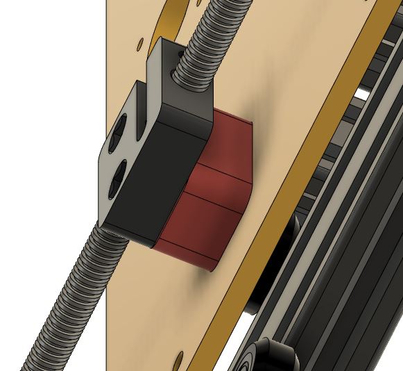
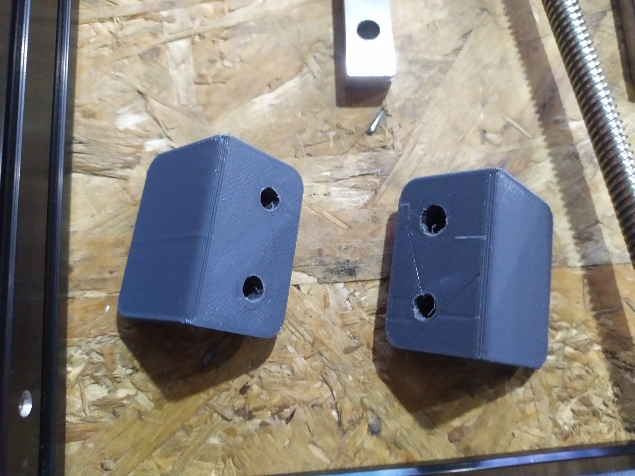
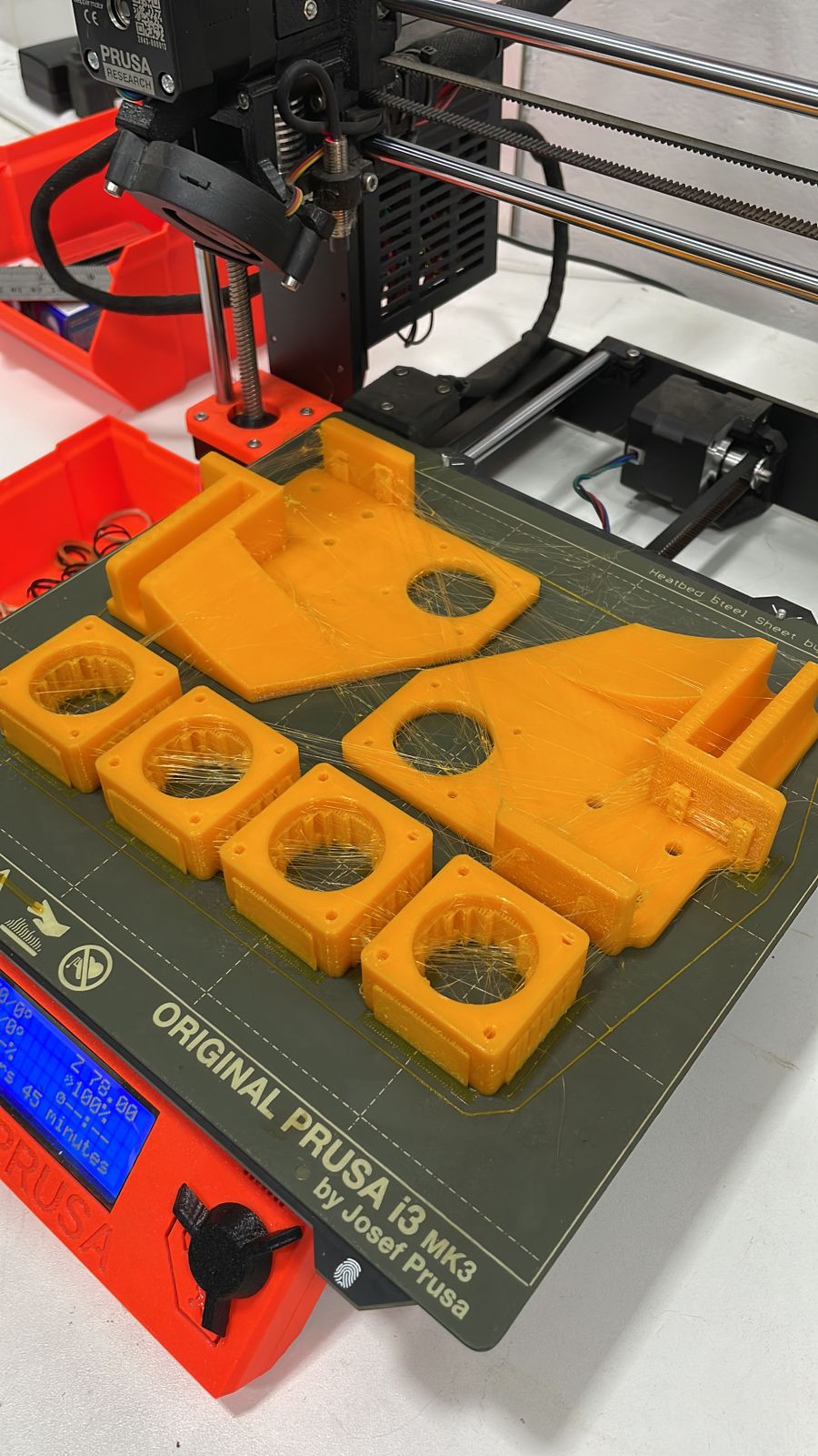
There is a 3D printed part to hold the anti-backlash nut precisely in place, to keep the leadscrew aligned and not to bend.
![]()
There is a 3D printed Spacer between the sidepanel and the wheel to ensure it is properly rolling on its rails. In the other side, there are excentric nuts to be able to tension the wheels.
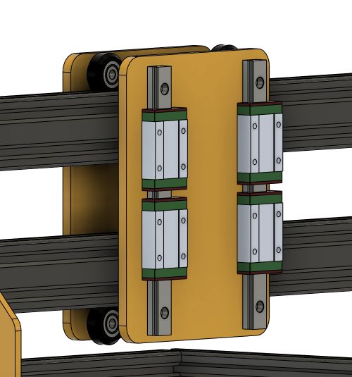
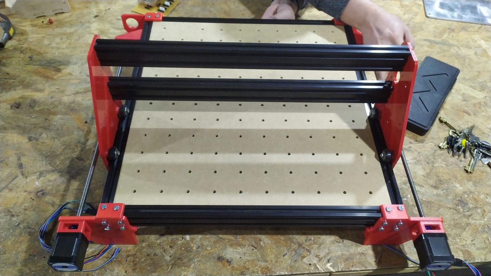
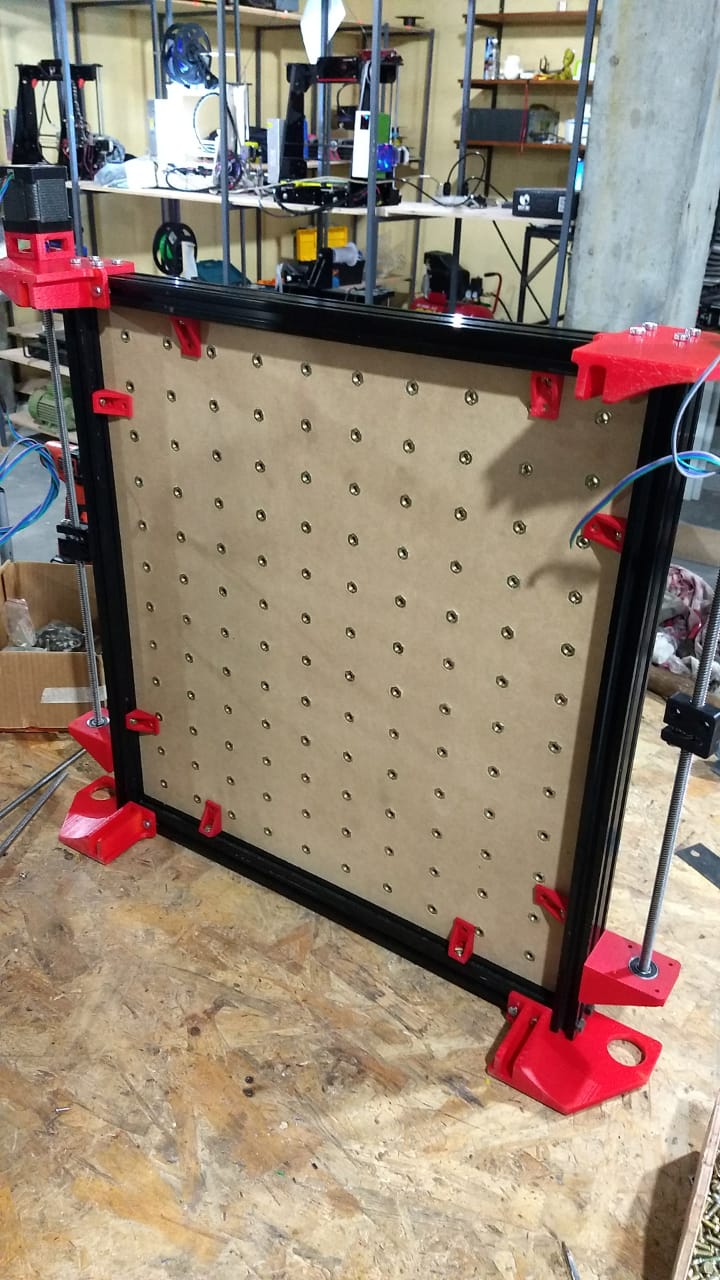
Same principle on the X axis but it has holes threaded on the aluminium to be able to bolt the linear rails in place with M3 screws. I added a rear panel but I think it won´t be necessary since the aluminium is very rigid.
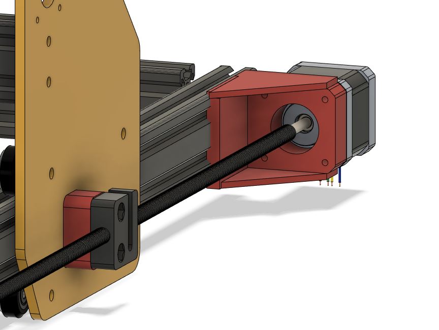
There is a 3D printed motor mount for both Y axis motors.
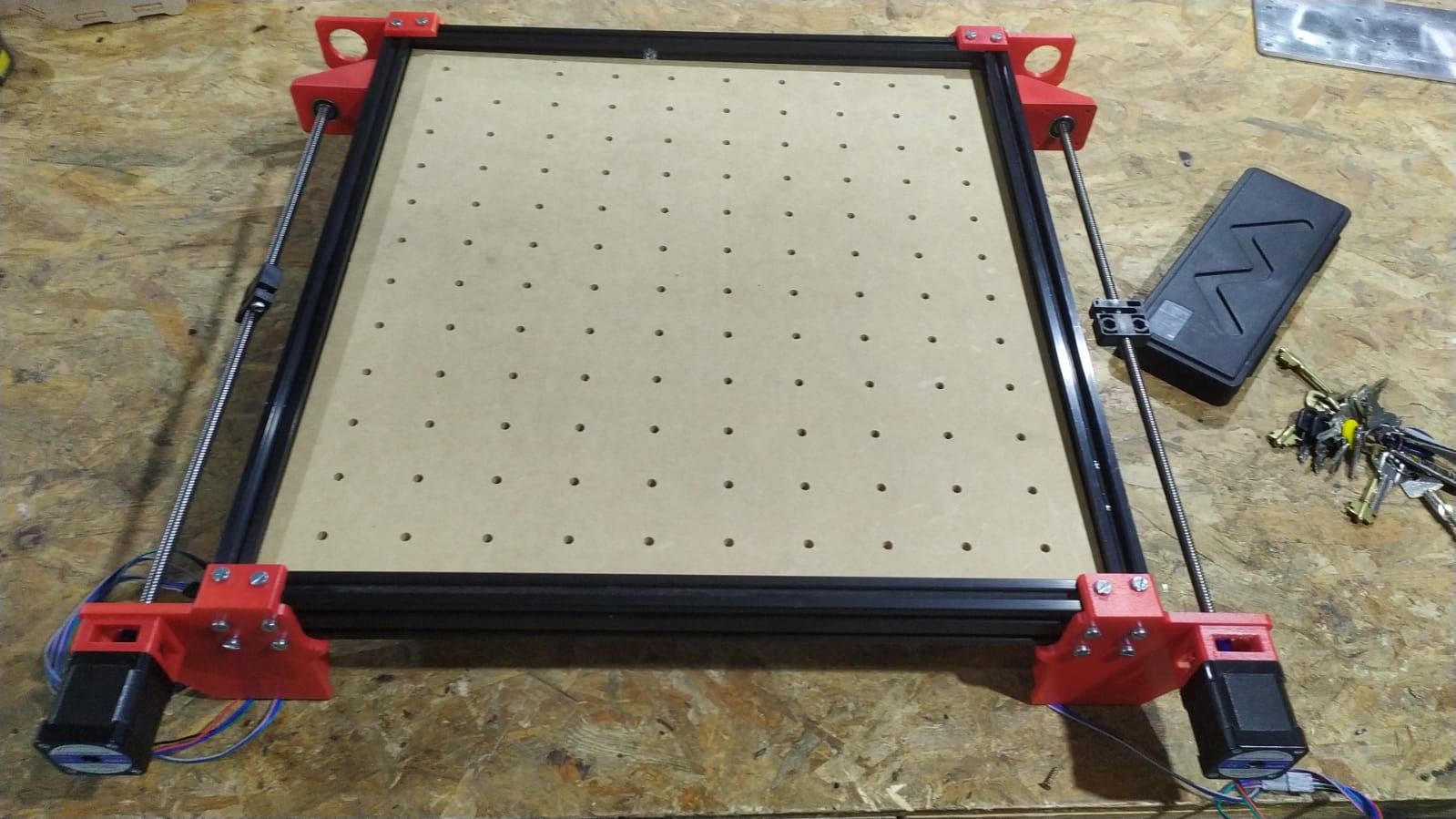
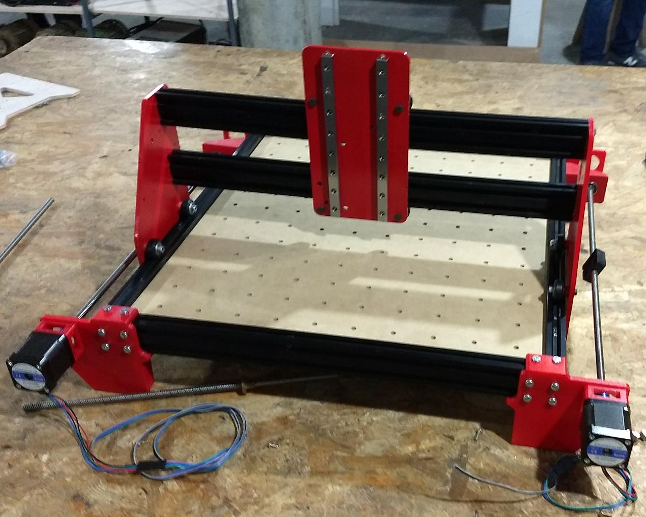
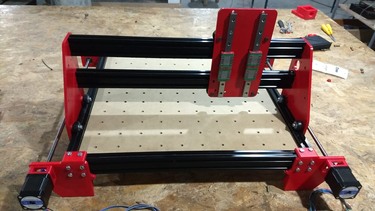
3- Mechanical Fabrication.
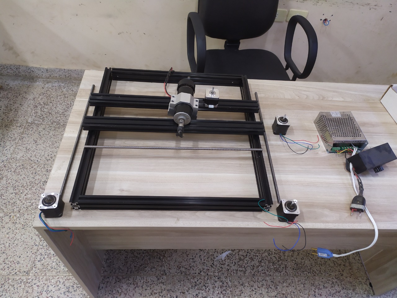
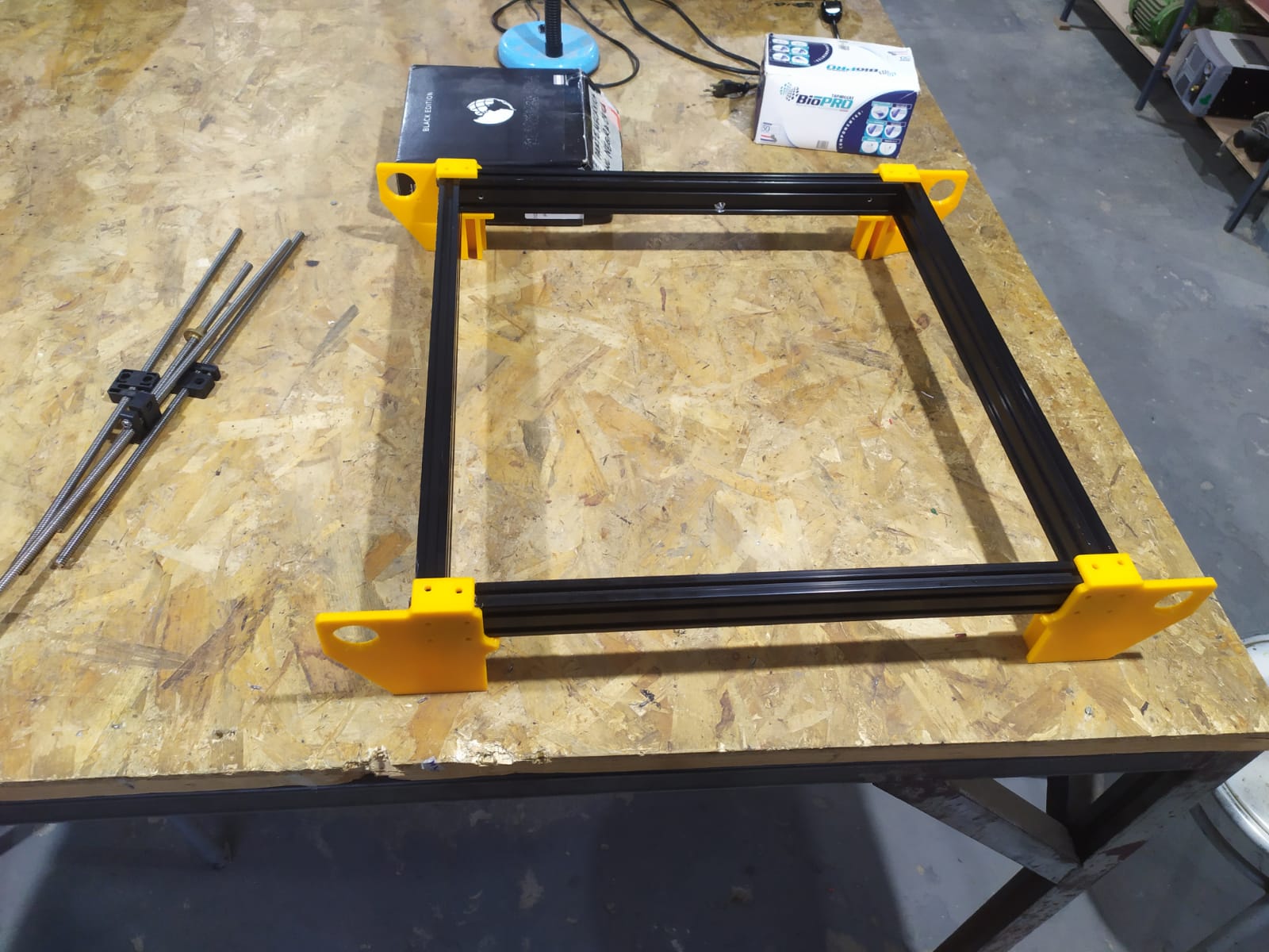
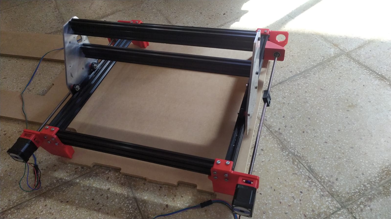
First steps assembling the machine.
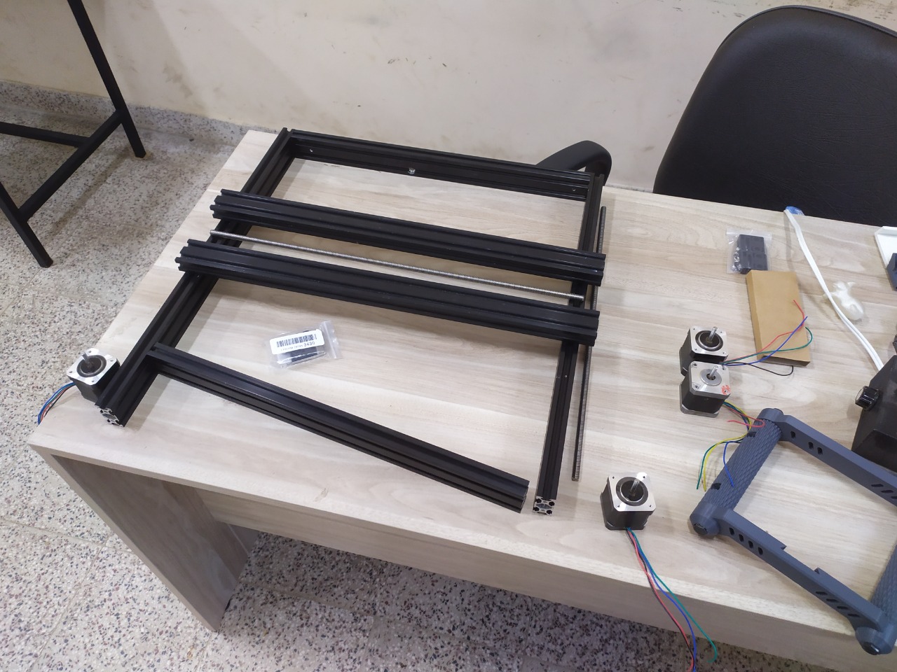
I 3d printed some pieces to help me drill the aluminium profiles and used m6 bolts to join the frame togetter
Prototyping
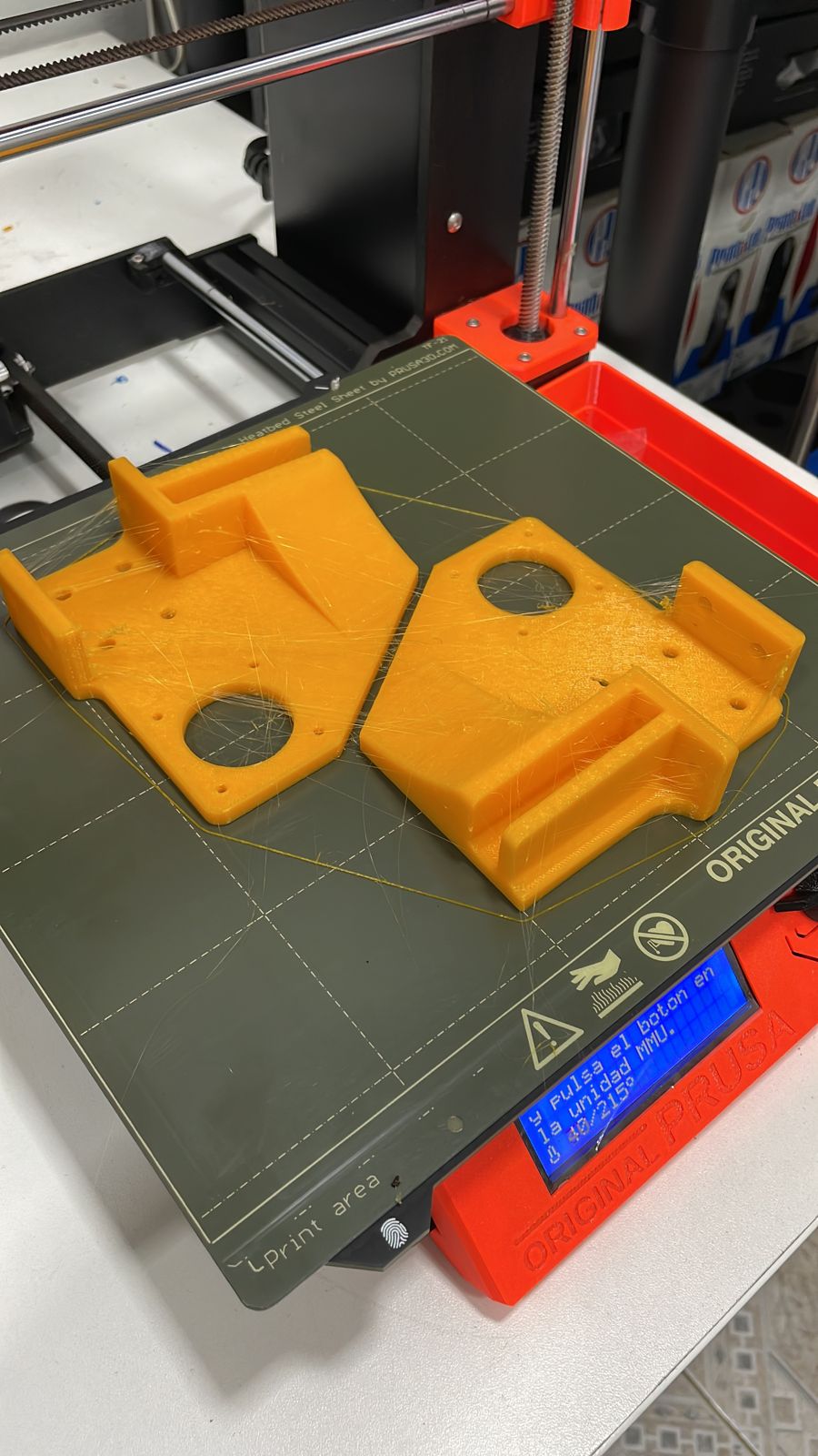
3D printing the parts
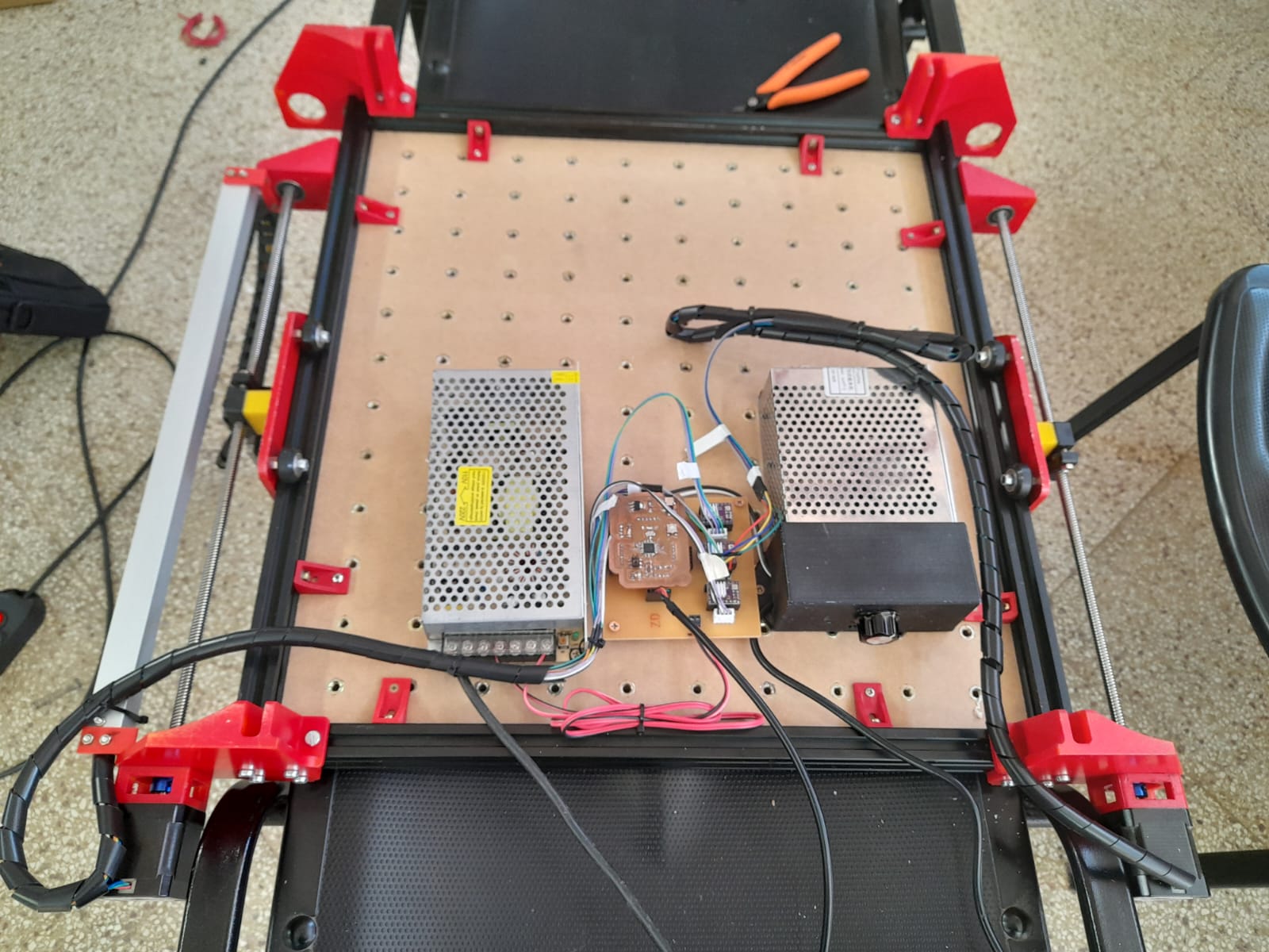
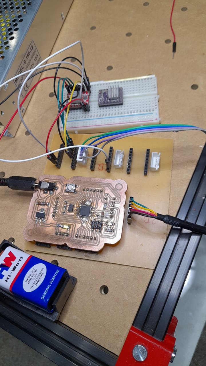
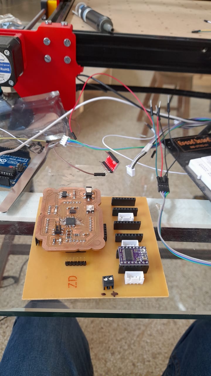
4- Motherboard and electric connections
On week 11 I started my fabduino board.
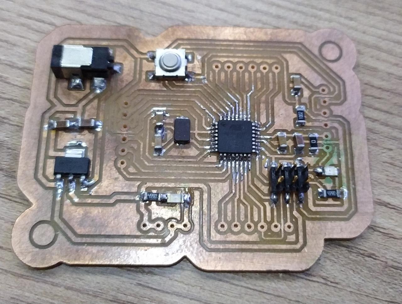
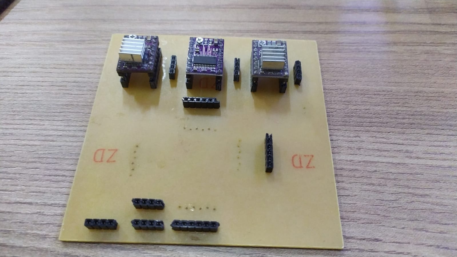
And using a cnc Shield based on abdon Rotela´s Machine desing board
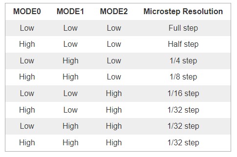
I have changed the microstepping on the original motherboard, so that the motors woudn´t vibrate too much in ful step mode.
Following the microstepping resolution table, I shorted the microstepping pin into 1/32 microstepping.
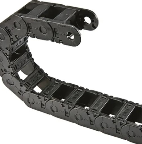
5- Casing and Cable management.
For cable management, I used a cable chain that I´ve got from Amazon.
6- Firmware and Control Software.
Motherboard firmware
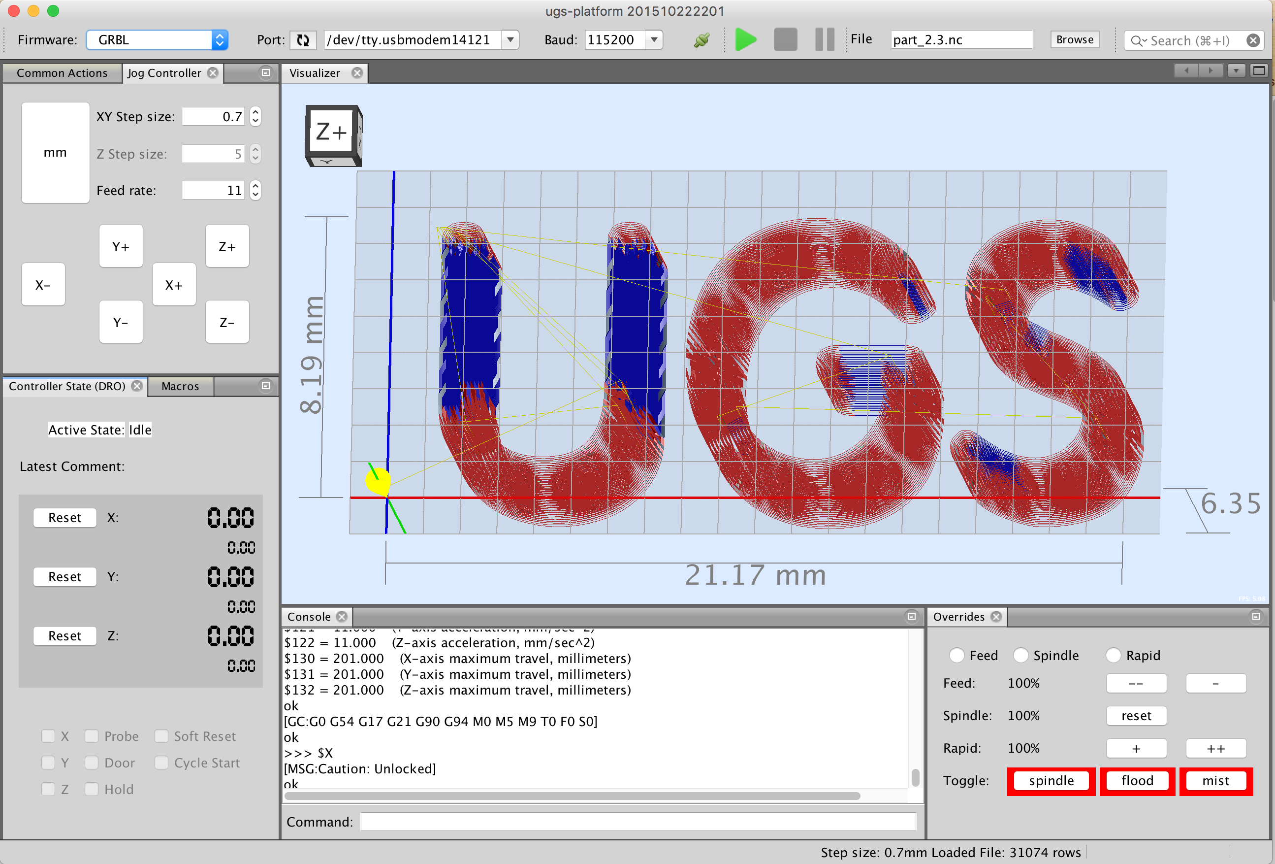
Machine control Software
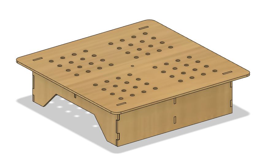
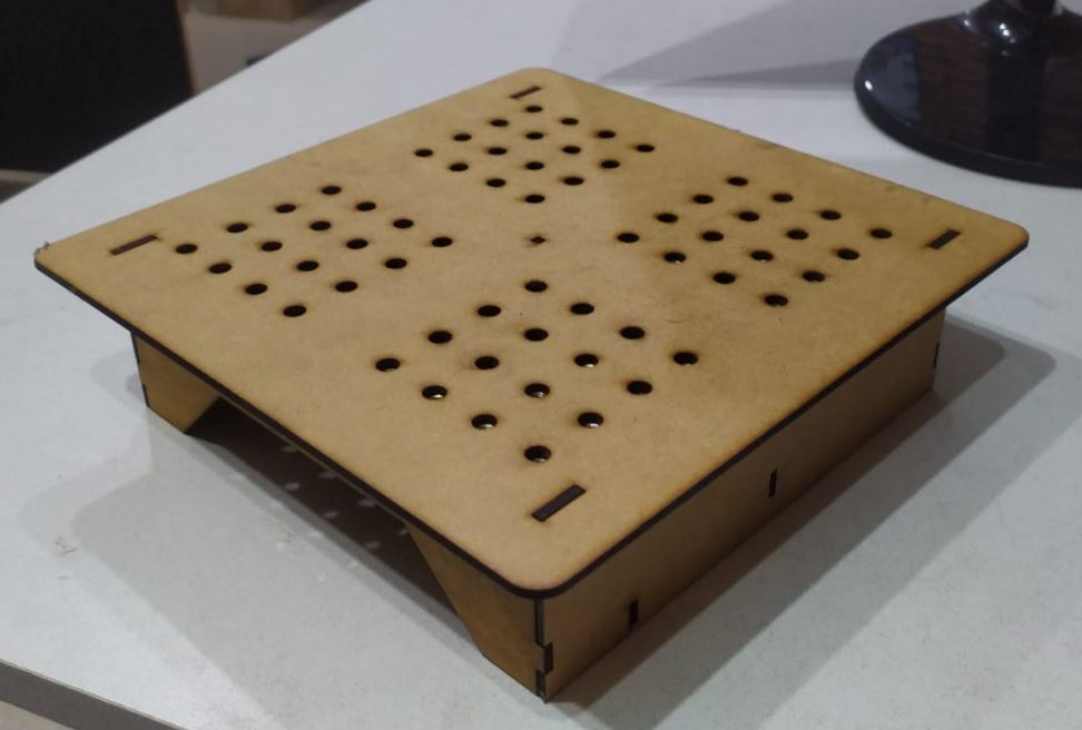
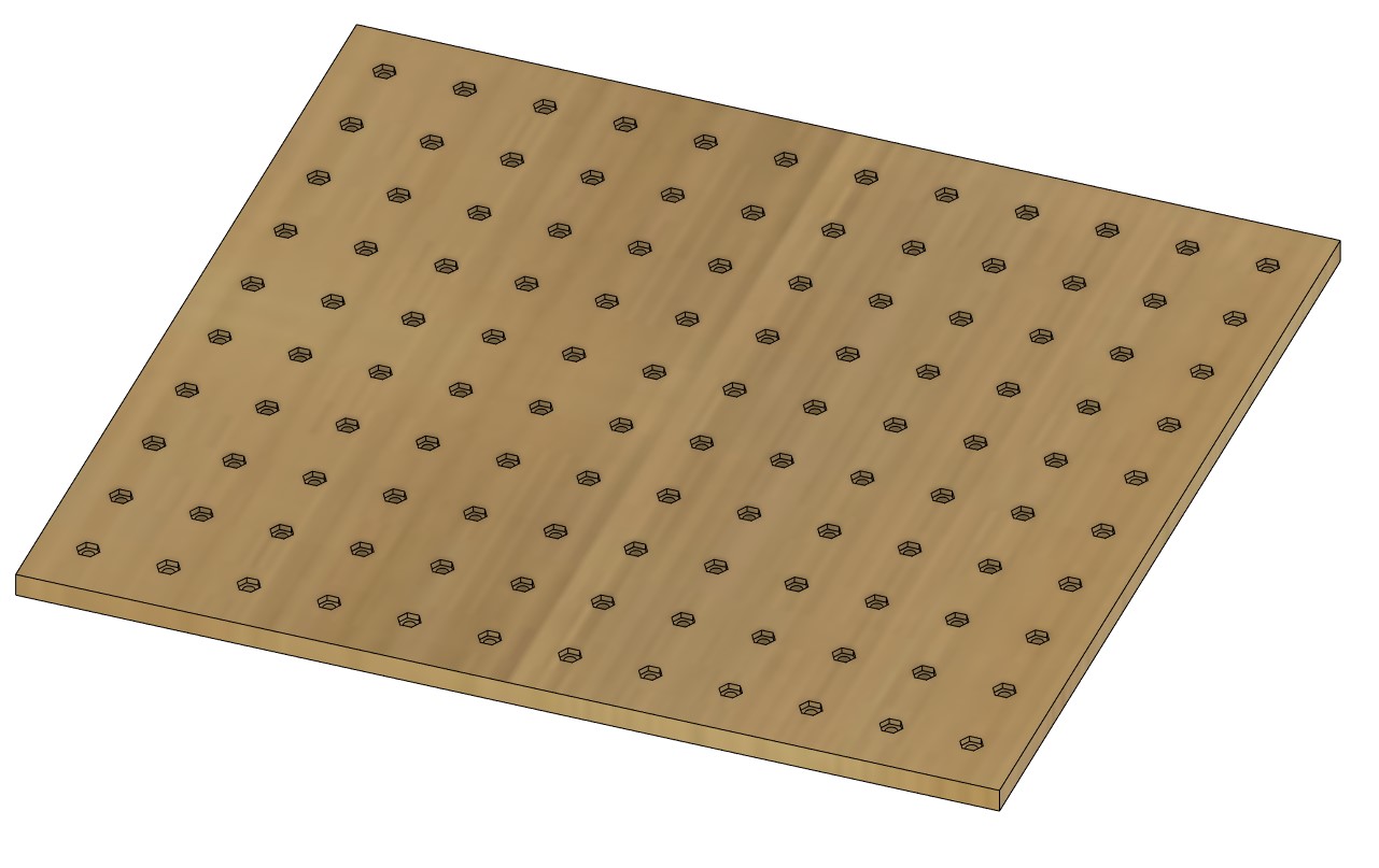
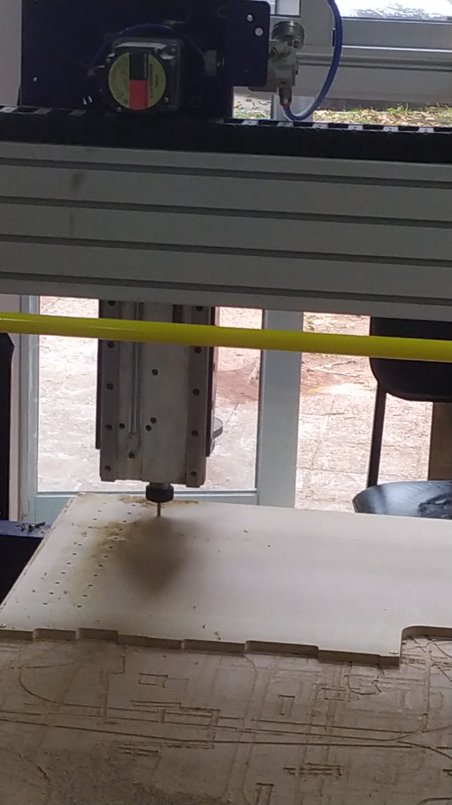
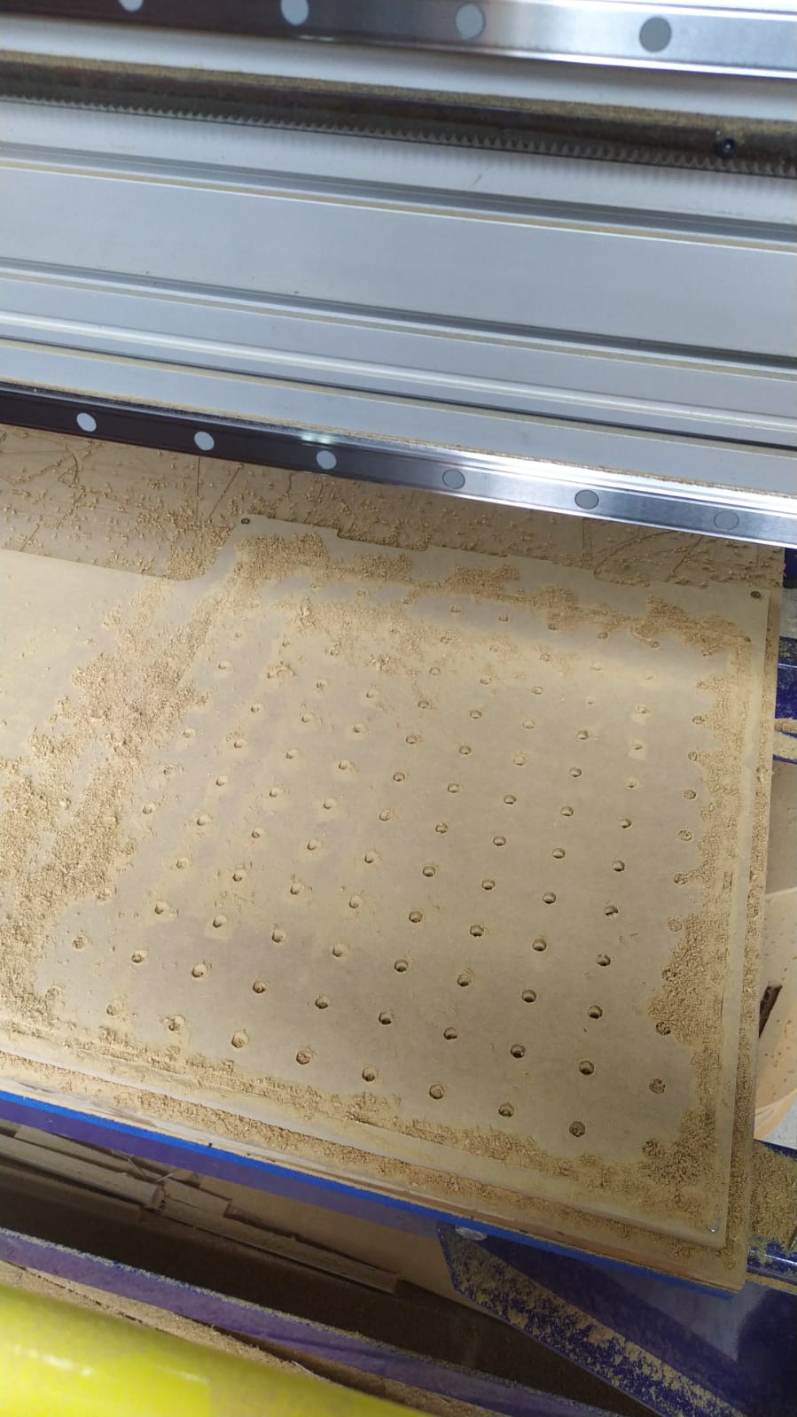
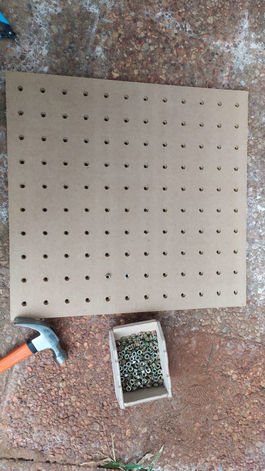
7- Clamping System
I started designing using fusion 360, this was my first idea but I realized I had to change a few details before start prototyping. For example, I have to design a way to attach the aluminium profiles to the clamping table. So in the laser cutting week, I designed a smaller clamping table prototype to start testing ideas.
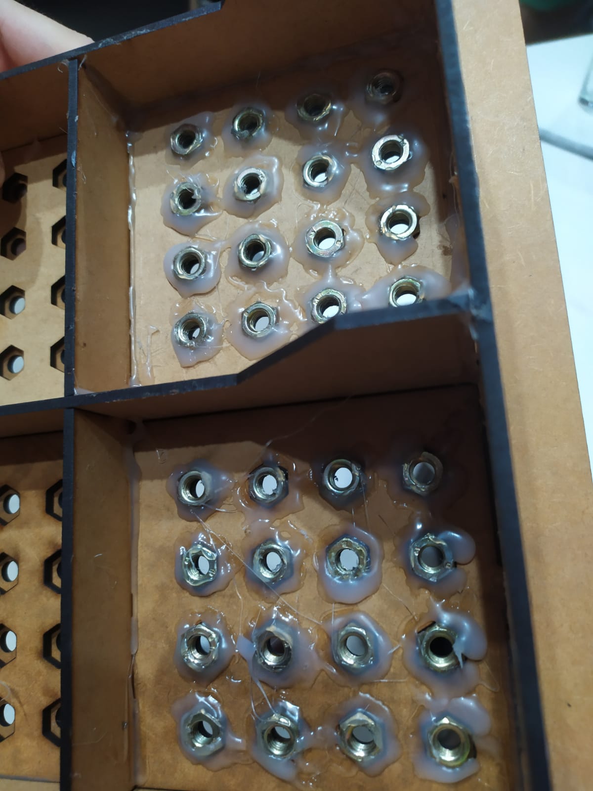
I used hot glue to attach m6 nuts to the botom of the clamping system and later I have to design
The clamping gadgets are yet to be designed.
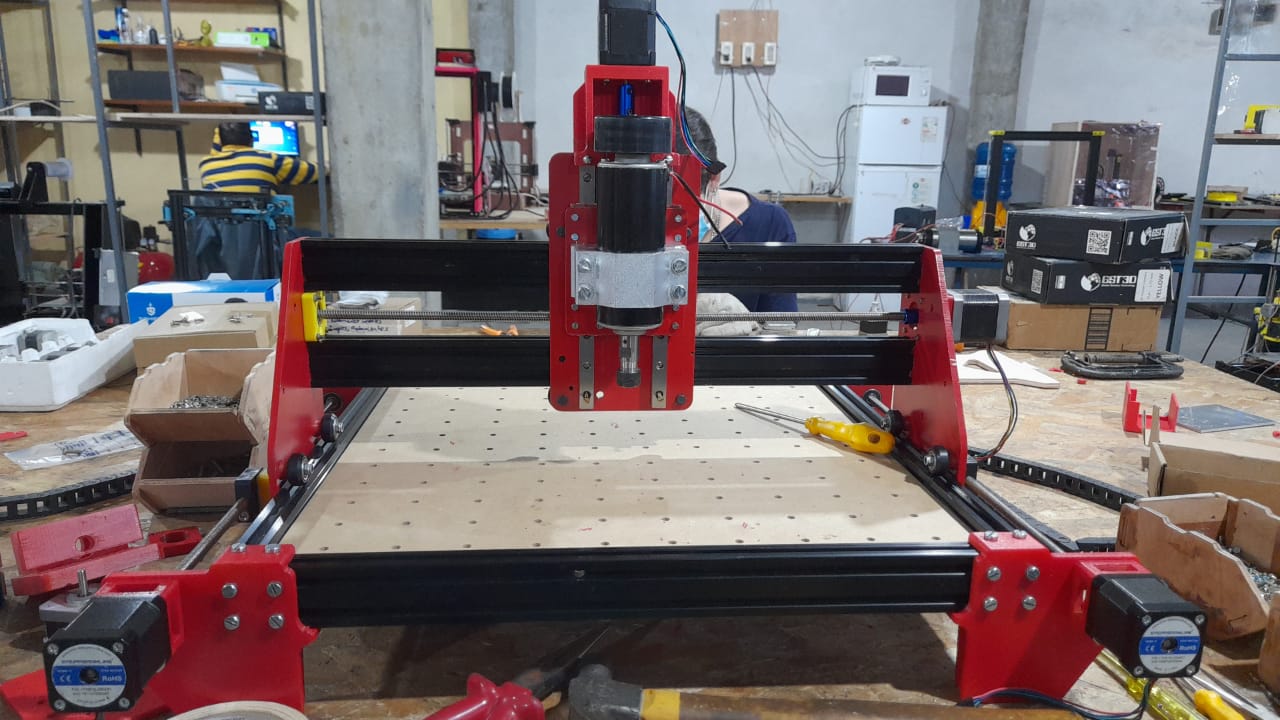
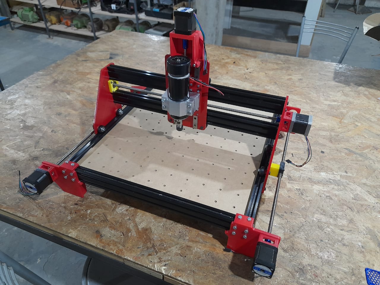
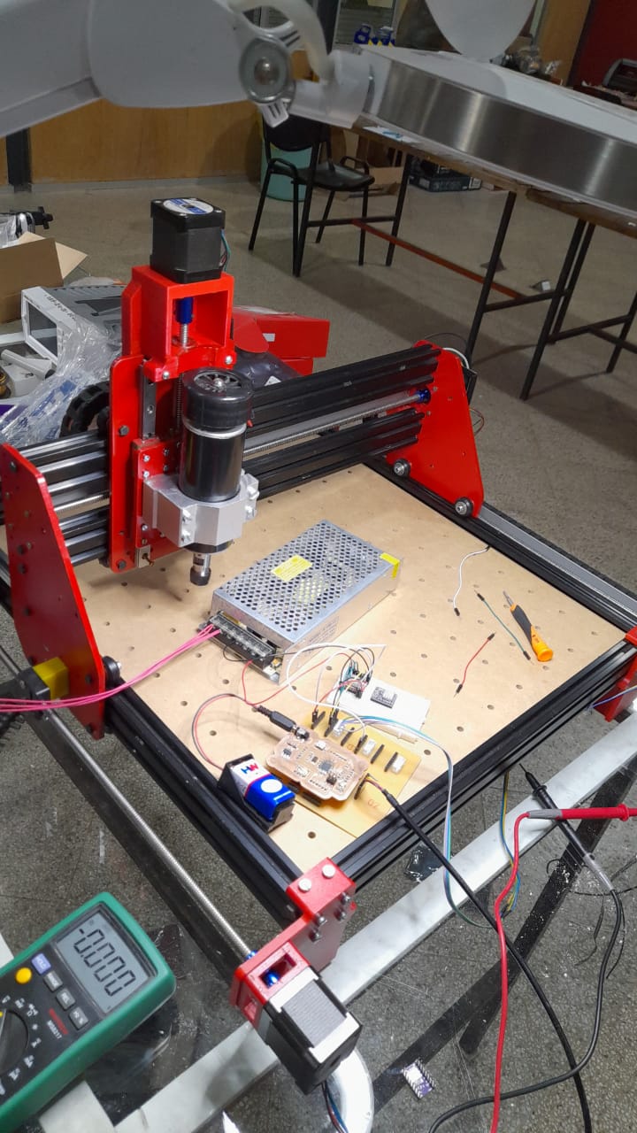
8- Testing
Fab academy Assessment Questions and Answers
What materials and components were used and How much did they cost?
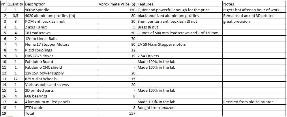
Where did they come from?
Most of them I already had and/or savaged from my lab, but you can buy them if you would like to replicate the machine.
What parts and systems were made?
Parts made
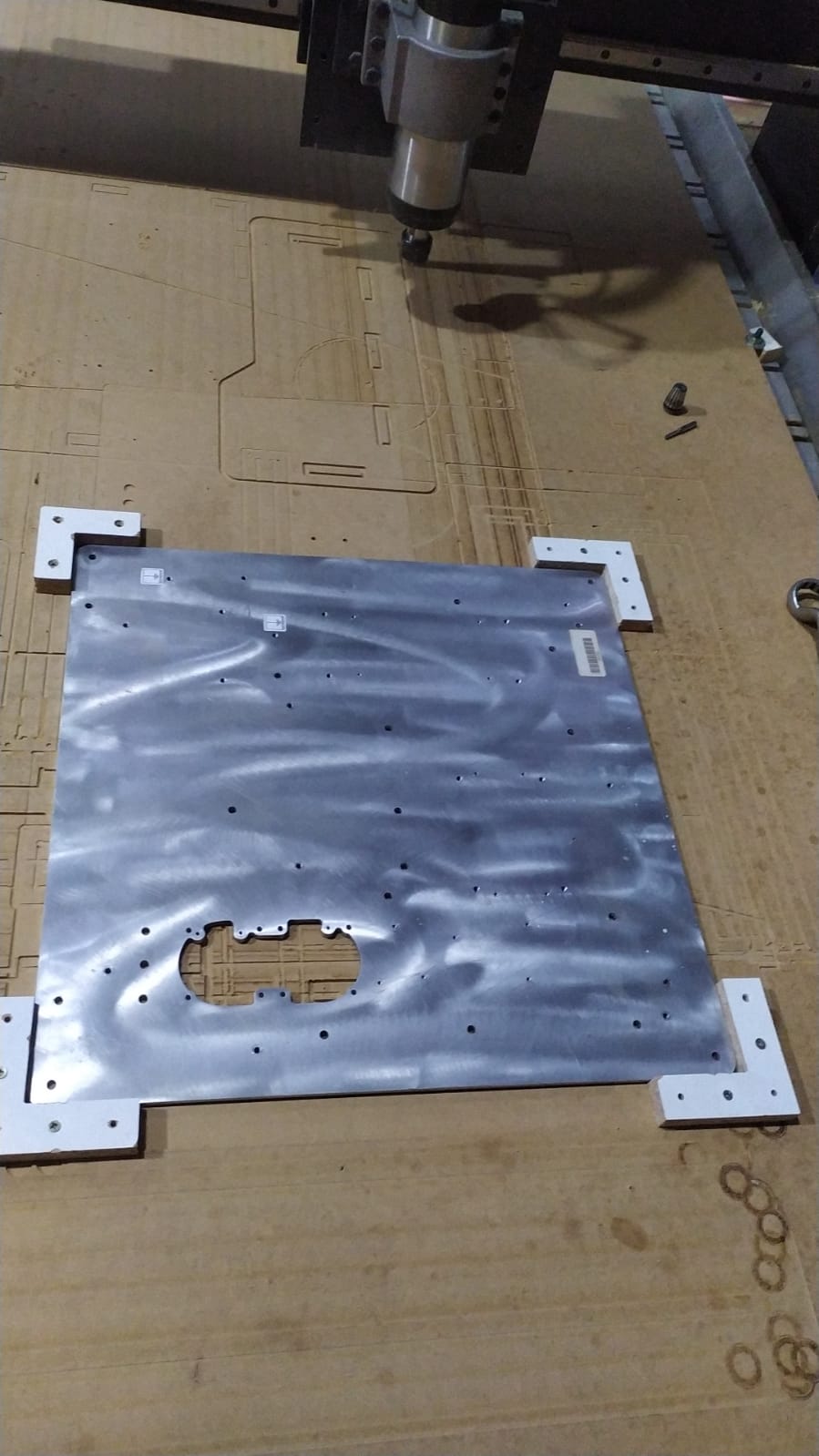
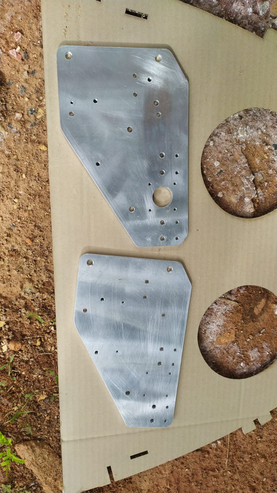
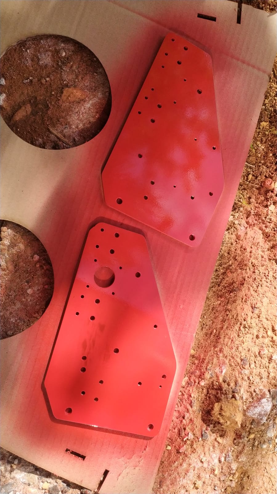
- CNC milled Aluminium panels.
- CNC routed Clamping surface.
- 3D printed motor mounts.
- 3d printed bearing mounts.
- 3D printed m6 clamps.
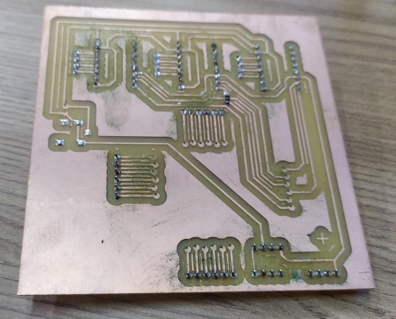
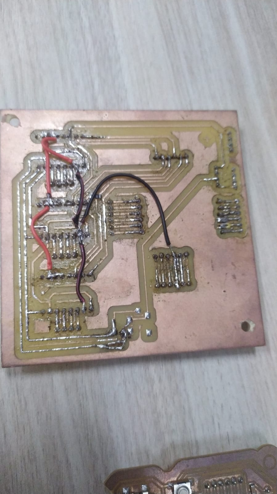
- CNC milled PCBs (motherboard and cnc shield).
- Laser cutted prototypes.
What processes were used?
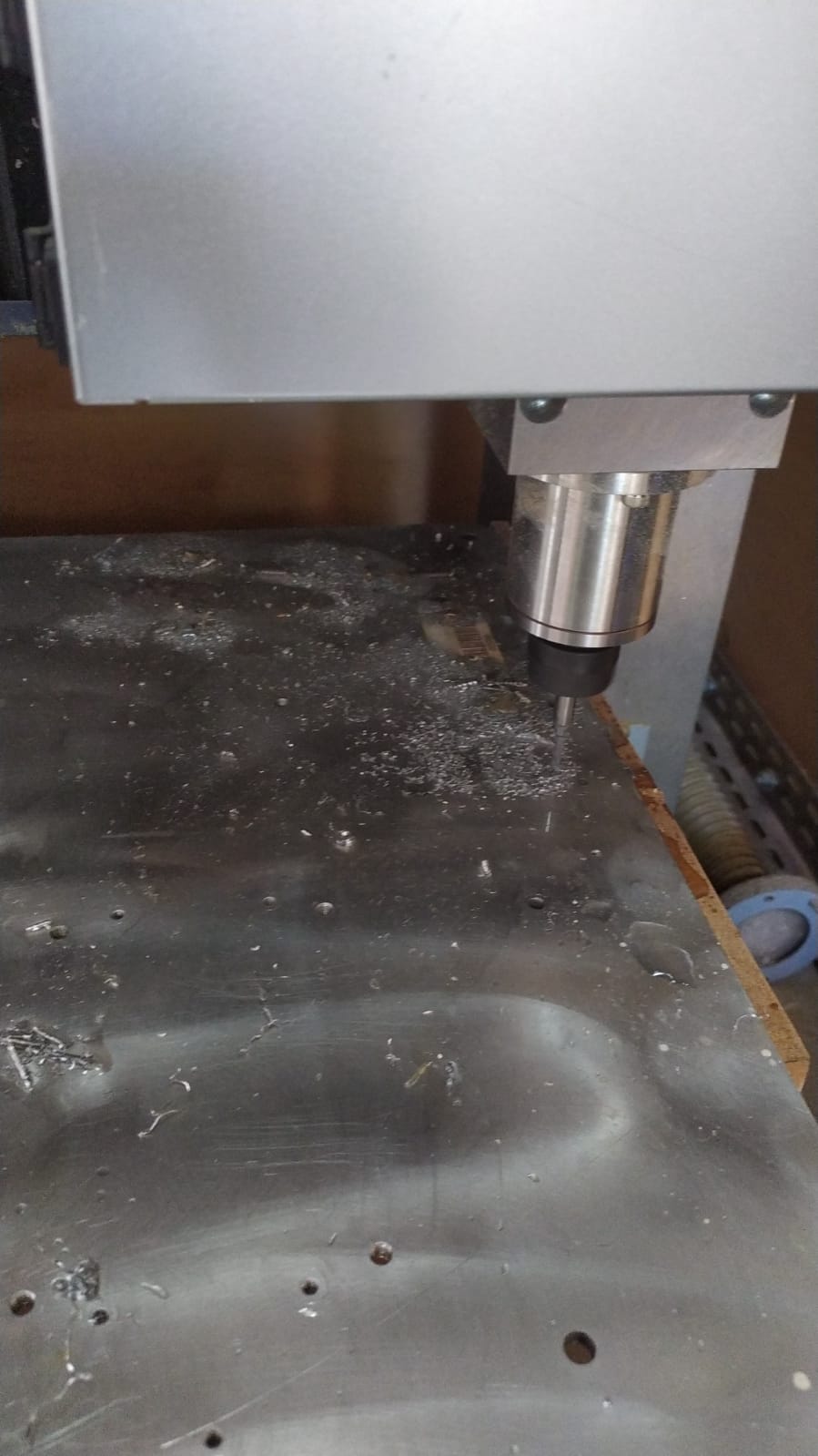
- CNC milling
- 3D printing
- Laser cutting
- Good old manual assembly.
- a lot of testing.
What questions were answered?
- Was it stiffer than 6mm wood?
Yes, the machine was quite sturdier than all the wooden machines I have made, it made me happy because I want to mill aluminium in it in the future.
- Will my mainboard work?
It worked nicely after a few attemps, at first I fried the main IC, and was wondering what the problem was, after Changing the IC, The X axis worked fine but the other 2 axis didn´t work, later I saw it was a soldering problem, and solved it by soldering with a lot of patience
-
will the Y motors be able to handle the 2Amps connected in series?
-
will it be enjoyable to operate?
What worked? what didn´t?
- Everything worked fine at the end, what I couldn´t do was to add some functionalities like endstops or stress test the machine.
How was it evaluated
- movement was tested, and also I did some engravings with the machine.
What are the implications?
- This machine will be a wonderful CNC to make other machines, because of it´s low cost and rigidity, It can be build at any fablab and provide a helpful fabrication tool.
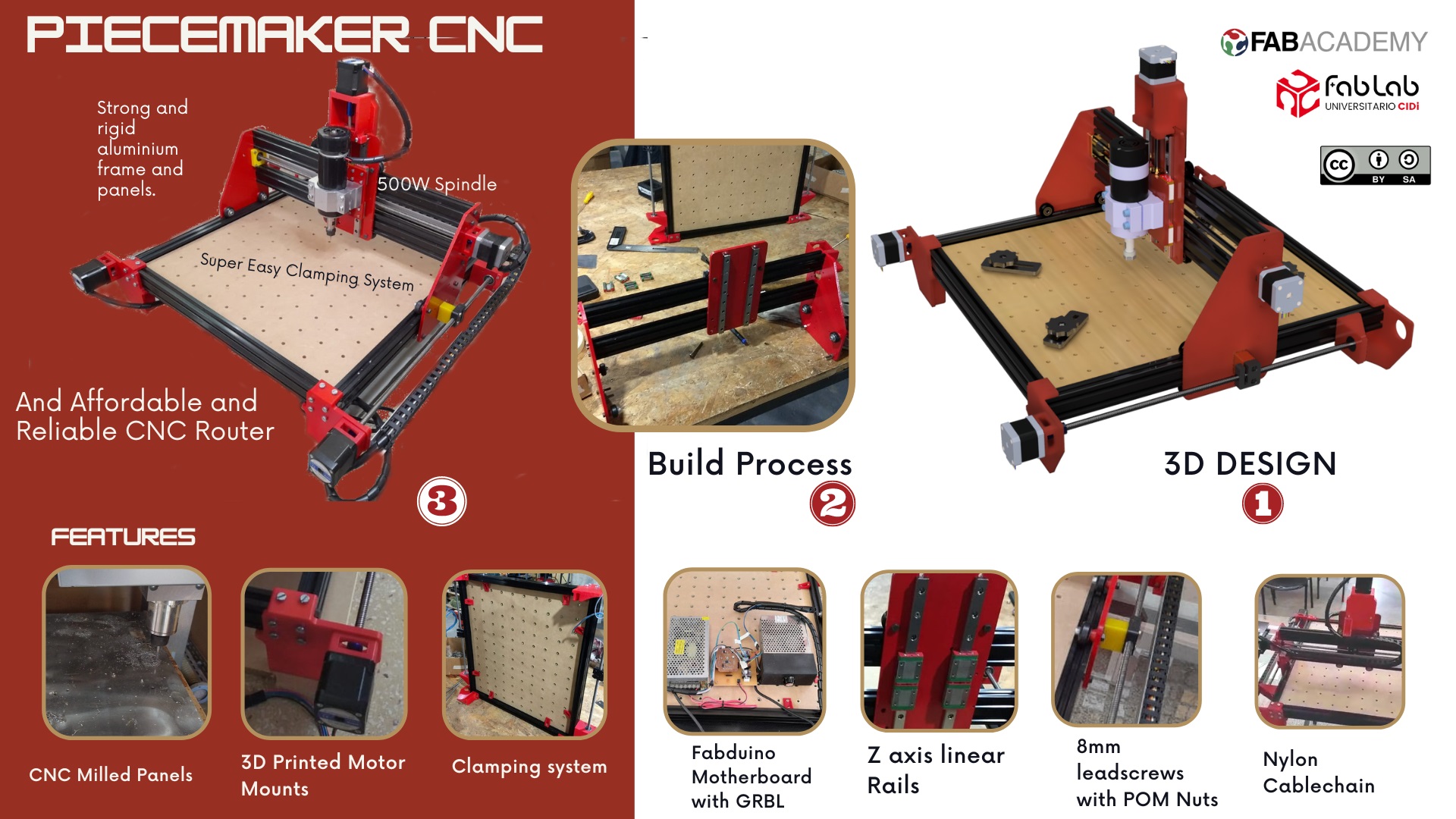
Summary slide
Videos
Design Files in fusion 360
You can download and print all the parts if you want to replicate this machine.